eISSN: 2574-9927


Research Article Volume 2 Issue 3
1Schneider Electric, France
2Materials Science and Technology Division, National Institute for Interdisciplinary Science and Technology, India
3University of Montpellier, Claude Bernard University-Lyon 1, France
Correspondence: Renaud Metz, Laboratory Charles Coulomb (L2C), University of Montpellier, Claude Bernard University-Lyon 1, Place Eugene Battalion, Building 11, Montpellier France, Tel +33(0)467-144855
Received: November 30, 2017 | Published: June 27, 2018
Citation: Boucher S, Hassanzadeh M, Ananthakumar S, et al. Interest of nonlinear ZnO/silicone composite materials in cable termination. Material Sci & Eng. 2018;2(3):83-88. DOI: 10.15406/mseij.2018.02.00039
Downsizing medium or high voltage equipment requires the optimization of electric field distributions in the device and in the surrounding environment in order to master local high electric field strengths leading to partial discharges along the surface of the dielectric materials, prompting accelerated material ageing or in worse case dramatic failure. The purpose of this paper aims to compare for a cable termination both strategies namely resistive and capacitive (or dielectric refractive) field grading material where electrical passive or active fillers of same permittivity are respectively added to an insulation host matrix. Under both AC and transient regime, nonlinear resistive field grading shows a better effectiveness as far as electric stress control is of concern.
Keywords: nonlinear materials, field grading materials, cable termination
A common problematic in High Voltage (HV) and Medium Voltage (MV) applications is the presence of local triple points. A triple point is the junction between three media characterized by a specific permittivity; for instance: air (relative permittivity ≈ 1), a conductor and a dielectric (relative permittivity > 1). In this location, the control of the electric field is essential in order to minimize the risk of partial discharge (corona effect) or surface electrical discharges. In addition, surges (transient overvoltage imposed by lightning and switching operations) may lead to premature degradation of the dielectric material.
A stress grading material may be an appropriate answer to manage the electrical field by spacing the equipotential lines relieving the triple points. Two groups of materials exist: resistive and capacitive stress grading materials. The first one are semi-conducting, there are governed by the conduction current and have a nonlinear resistivity (the material has a nonlinear conductivity with a dependency of the conductivity (E) with the electrical field (E)). In AC steady state, the current density may be expressed as:
where is the direct current conductivity, is the angular frequency measured in radians per second , ϵ_0 the vacuum permittivity, the electrical displacement field which is, in first approximation, related to the electrical field by the complex relative permittivity:
The second group of materials are insulating, there are governed by the displacement current:1-3
Several publications reported on those materials and expected applications are listed in Table 1.4-20 (The reference10 is somewhat exotic and exciting since the field grading material is obtained by centrifugation. The resulting material is a semiconductor having graded concentrations and hence spatial graded permittivity). Only few of them compare formally both stress grading methods. Moreover, due to the high permittivity of ZnO/silicone composites ( > 10) it is often difficult to know if the materials are truly working in resistive field grading (nonlinearity active) or capacitive field grading (nonlinearity inactive). The goal of this work is to compare both methods by being focused on shielded cables. The purpose is to get a deeper understanding of resistive or capacitive electrical field gradation from a simulating perspective.
Ref. |
Material studied |
Application |
Resistive or capacitive stress grading material |
Stress grading varnish |
Rotating machines |
Resistive and capacitive |
|
Review |
High voltage insulator |
Resistive and capacitive |
|
- |
Cable joints and terminations |
Resistive and capacitive |
|
Varnish and tape |
Motor and generator coils |
Resistive and capacitive |
|
- |
General study |
Resistive |
|
Commercial shrink stress control tube |
Cables |
Resistive |
|
- |
Cable terminations |
Resistive |
|
ZnO fillers inside SiR matrix |
Cable terminations, joints and rotating machines |
Resistive |
|
Composite made of microvaristor filled silicone rubber |
Sheds and sheath |
Resistive |
|
Composite made of silicone and nonlinear fillers |
Cable termination |
Resistive |
|
12-15 |
Composite made of silicone and nonlinear fillers |
- |
Resistive |
Composite with microvaristor fillers |
Cable terminations |
Resistive |
|
Field grading material characterized by the spatial distribution of dielectric permittivity obtained by centrifugal force |
Disk-type solid insulator |
Capacitive |
|
Functionally graded material |
- |
Capacitive |
|
Materials with different permittivity |
Cable terminations |
Capacitive |
|
Oil-impregnated paper |
Bushing |
Capacitive |
Table 1 Resistive and capacitive stress grading materials in the literature
In this purpose, a resistive field grading material where nonlinear ceramic fillers are added to a silicon host matrix is studied and is compared to a fictive linear material with the same permittivity which symbolizes the capacitive grading method.
The reference specimen is chosen as a composite made of ZnO varistor particles with an average size between 100 and 200 µm added in 35 vol. % in silicone matrix. Nonlinear composites have been prepared by grinding industrial polycrystalline ceramic varistors of doped ZnO in different range of aggregate sizes (50-100, 100-200 and 200-315 µm). Then ZnO aggregates have been dried at 150 °C in order to suppress residual humidity. After this operation, the particles have been slowly mixed (50 rpm) to a silicone matrix (Powersil 600 from Wacker, weight ratio 9:1). After degassing, the mixture has been cured at 110 °C during 10 minutes. The sample tested were cylinder with a diameter of 25 mm and a thickness of 3.4 mm. Current density-electric field (J-E) profile (Figure 1) has been carried out with a voltage generator (5 kV) in AC voltage.
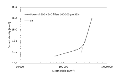
Figure 1 Current density and fitting as a function of electric field for a 100-200 µm 35% ZnO-silicone composite in AC voltage.
The experimental characteristic parameters were extracted from equation (1) by fitting the J-E final experimental points. These parameters are represented in Table 2 with the experimental permittivity measured at 50 Hz.
(1)
|
Nonlinear composite 35vol.% 100-200µm |
Relative permittivity ɛr at 50 Hz |
10.5 |
Electric threshold Es (V.mm-1) |
265 |
Nonlinear coefficient α |
12 |
Conductivity σ0 (S.m-1) |
6.7 10-8 |
Table 2 Experimental properties for ZnO-silicone composite
σ(E) the electrical conductivity, s0 : a characteristic conductivity scale which is assumed to be the small-field conductivity, and Es the breakdown voltage for which J and E become non-linear. The nonlinear s determines the rate of change in current density during the transition state from an insulator to conductor. The low field conductivity is selected at the point where the nonlinearity begins, here we assume this point at 2.5 105 V.m-1. For linear materials, the linearity coefficient value is 0 and the equation (1) becomes: . For a perfect nonlinear material so:
Electromagnetic simulations have been carried out by a Finite Element Method (FEM) software called Flux2D® version 12.3.1 provided by Altair which used Maxwell equations and the constitutive equations of matter:
Conductor medium |
|
Magnetic medium |
|
Dielectric medium |
|
with E the electric field in Vm-1, D the electric induction in Cm-2, B the magnetic induction in Tesla, H the magnetic field in Am-1, J the current density in Am-2, the conductivity of the medium in Sm-1, the permeability in Hm-1 and the permittivity of the medium in Fm-1 measured at 50Hz. (The electric induction was assumed as linear with the electric field, although very new experimental works report that besides nonlinear conductivity, ZnO composites possess field-dependent permittivity under a pure AC field.21
The geometry is designed by the operator by points (the relative accuracy between points is 10-8), lines and faces. (For instance, a cylinder in 3D is associated with 4 faces, although in 2D-axysymetry only 1 face: a rectangle). From this geometry each face is meshed with polygons with three edges and three vertices also named nodes. The relative accuracy between nodes is 10-10. For each polygon, two modes are used: steady state or normal operating conditions at 50 Hz with 66 kV applied voltage (named harmonic), and transient mode where an impulse voltage waveform is simulated by the equation : .
For harmonic mode, the equation (2) is solved:
(2)
where and are the conductivity and permittivity tensors expressed in Siemens and Farads, the pulsation of the voltage sinusoidal wave in s-1, V the voltage in Volts and j the complex number. In transient mode, the equation (2) becomes (3):
(3)
Whatever the mode, Flux2D uses different solvers as function of the linearity of the system. If the system is linear, that means equations of matter are of the type [A][X] = [B], where A is a square matrix of n x n size (with n lines and n columns), X is a column vector of size n, representing the unknown system, B is a column vector of size n, with known components. Flux2D uses a direct or an iterative solver. By default, a direct solver resolves the equations.
If the system is nonlinear, [A(X)][X] = [B], where the system matrix [A] depends on the vector solution [X] (here, the nonlinear equation is ), the solver used is based on Newton-Raphson iterative method. After resolution of the system, Flux2D gives local values such as electric field E and electric potential V or global values which result from integration on a domain, a domain being a group of faces. Figure 2 shows a single-core cable termination of a XLPE (cross-linked polyethylene) cable when the grounded shield has been removed.
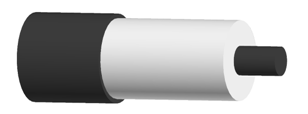
Figure 2 Single-core cable termination scheme. The conductor is depicted as a black cylinder embedded in a white polymer insulator shielded with a black tube (V = 0V)
This configuration is critical because at the end of the ground shield there is a triple point circumference zone between air, grounded shield and insulating material where the electric field can reach the dielectric rigidity of air, resulting in corona discharge, and eventual destruction of the insulation. The idea to reduce this unacceptable electric field enhancement is to prolong the ground electrode with a field grading tube of nonlinear material. Such field dependent material has indeed the ability to distribute the field by itself. To simulate this strategy, an axisymmetric representation is used. The geometry is detailed in Figure 3, where the end of cable is studied in the air. This geometry is studied in both AC steady state and transient voltage with the profile wave described as previously.
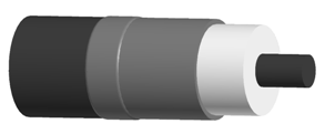
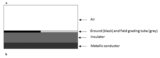
Figure 3 (a) Cable termination with field grading tube. The conductor is depicted as a black cylinder embedded in a white polymer insulator above which a grey tube has been heat-shrunk in such manner that it is connected to the shield (black) that has been grounded. (b) Representation in 2D axisymmetric of the configuration depicted in a. by an axisymmetric geometry of the cable termination: the radius of the conductor is 16.5 mm, the radius of the insulator is 45 mm, the thickness of the grounded shield and of the field grading tube is 5 mm.
Steady state AC voltage
The geometry is studied in AC voltage at 66 kV with a frequency of 50 Hz. Three cases were treated: a cable termination without field grading tube, a cable with a nonlinear grading tube with a permittivity of 10.5 (resistive field grading), and a cable with a fictive linear material with a permittivity of 10.5 (capacitive or refractive field grading) in order to validate the effect of the nonlinearity.
On the Figure 4 maps of the electric fields in the XLPE layer and in the air are depicted. It appears that the dielectric field decreases with the capacitive field grading tube and even more with a resistive field grading tube. The field reductions have been reported in Table 3.
|
Without field grading tube |
With linear field grading tube ( = 10.5) |
With nonlinear field grading tube |
Electric field at 66 kV (kV.mm-1) |
8.6 |
2.3 |
0.2 |
Relative decrease |
- |
-73% |
-98% |
Table 3 Electric field at triple point circumference zone for the three simulated configurations
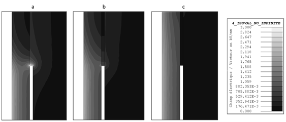
Figure 4 Maps of tangential electric field magnitudes in the case of cable without field grading tube (a), in the case of cable with a linear field grading tube with a permittivity of 16 (b) and in the case of cable with nonlinear field grading tube (c) in AC voltage 66 kV, 50 Hz.
From the Table 4, we can clearly grasp that without field grading tube the electric field reaches 8.6 kV.mm-1 in the air. That is more than about three times the dielectric rigidity of the dry air. At the difference, the linear field grading tube (acting as a capacitive field grading) allows to reduce the electric field by -73% at this point to 2.3 kV.mm-1. With a nonlinear field grading tube there are no ambiguity, electric field is far below dielectric rigidity of the air and is reduced by -98 %, thus risk of surface electrical discharges or flashover are even more limited.
|
Unshielded |
With linear field grading |
With nonlinear field grading |
Electric field at triple point (kV.mm-1) |
10.3 |
3.4 |
2.1 |
Relative decrease |
- |
-67 % |
-80% |
Table 4 Values of electric field at triple point for three configurations: cable termination unshielded, cover with a linear and nonlinear field grading tube respectively.
Figure 5 shows a schematic of the equipotential lines in AC cable termination in cross section. Along the cable, the radial stress is nonlinear but confined between the conductor and the shield. At the discontinuity, where the shield has been removed, the concentrated field in the insulation spread out causing a risk of flashover at the surface of the terminated cable. The implementation of a field dependent material along the shield allows to limit the spread out (Figure 5). The voltage equipotential lines have been displaced away from the triple points toward the end part of the nonlinear material.
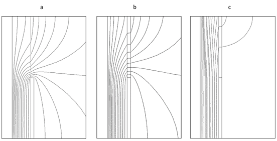
Figure 5 Equipotential lines in the case of cable without field grading tube (a), in the case of cable with linear field grading tube (b) and in the case of cable with nonlinear field grading tube (c) in AC voltage 66 kV.
Transient voltage
The same three cases are studied in transient voltage. The electric field as a function of time at triple point is reported on Figure 6. Without field grading tube, electric field reaches a maximum at 10.3 kV.mm-1. With a nonlinear field grading tube this maximum electric field is reduced by -80% (2.1 kV.mm-1). In addition, the maximal electric field is reached earlier, 2.52 µs against 4.54 µs for both configurations: without coating and with linear electrical field. To summarize, when an overvoltage happens, a cable with a nonlinear field grading tube has a limited maximum electric field and this one is dispelled faster. In the Figure 7, the electric field maps are plotted when electric field is maximal as deduced previously from curves on Figure 6.
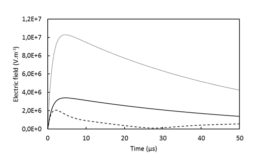
Figure 6 Electric field modulus at triple point as function of time for cable without stress grading tube (dotted line), cable with linear stress grading tube (full line) and cable with nonlinear stress grading tube (dashed line) in transient voltage .
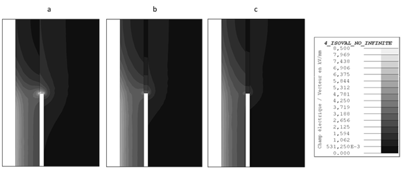
Figure 7 Maps of electric field modulus at respectively 4.54 µs, 4.54 µs and 2.52 µs in the case of cable without field grading tube (a), in the case of cable with linear field grading tube (b) and in the case of cable with nonlinear field grading tube (c) in transient voltage .
Table 4 confirms the previous conclusions: at triple point, electric field is clearly reduced by -80 % from 10,3 kV.mm-1 to 2,1 kV.mm-1 with a nonlinear field grading tube. Another interesting point is that the part of the insulating material which is bound to the conductor is less solicited because electric field is lower. Thus, if several surges happen during the lifetime of the cable, the insulating material will be less weary than a cable without field grading tube.
The Figure 8 shows that field grading tube, whatever the material, can spread more regularly the equipotential lines. Especially, with the nonlinear field grading tube the spaces between equipotential lines are larger than those with linear field grading tube with the same value of permittivity. This is another clue demonstrating that the grading is achieved by resistive field grading.
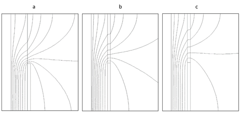
Figure 8 Equipotential lines at 4.54 µs in the case of cable without field grading tube (a), in the case of cable with linear grading tube (b) and in the case of cable with nonlinear field grading tube (c) under transient voltage .
We found that with a nonlinear material a maximum electrical field of 2.1 kVmm-1 is obtained. In order to reach an equivalent electrical field reduction with capacitive field grading a material permittivity of about 50 is requested (Figure 9). The Figure 9 was intended to show how the increase of the permittivity allows to reduce the field. It gives the equivalent permittivity requested to achieve the same amount of field reduction under impulse conditions. It is worth to notice that the time of decay remains of the same order of the capacitive field grading with a linear permittivity of 10.5: the field is dispelled about 1.8 times slower.
In this article, we have compared resistive grading composites with capacitive method through the application of electric cable. The strategy was to insert a field grading tube of nonlinear composite at the end of a cable and to compare its intrinsic ability to smooth the electric field distribution with a linear material tube of the same permittivity. A number of simulations demonstrate that in both AC and transient conditions the electric field distribution along the cable termination profile is significantly improved and under surge conditions the peak magnitude of the field is dispelled about 1.8 times faster. It is shown that an equivalent linear permittivity of 50 is requested to get the same field reduction with dielectric refraction.
None.
The author declares that they have no conflict of interest.

©2018 Boucher, et al. This is an open access article distributed under the terms of the, which permits unrestricted use, distribution, and build upon your work non-commercially.