MOJ
eISSN: 2576-4519


Mini Review Volume 4 Issue 1
1Human Machine Integration Laboratory, Arizona State University, USA
2AKE, Arizona State University, USA
Correspondence: Thomas G. Sugar, Human Machine Integration Laboratory, The Polytechnic School, Ira A. Fulton Schools of Engineering, Arizona State University, Mesa, AZ, USA
Received: January 31, 2020 | Published: February 28, 2020
Citation: Sugar TG, Redkar S, Hollander KW. Phase controller outperforms impedance controller for a hip exoskeleton. MOJ App Bio Biomech. 2020;4(1):25-28. DOI: 10.15406/mojabb.2020.04.00127
Developing controllers for exoskeletons has many challenging requirements: one of which is creating a torque command based on measured human data that that is in phase with the user (in-synchrony with the human gait). We show that the hip torque for walking gait can be modeled using a phase angle based on hip angular position and velocity. This model is superior to a standard impedance model based on inertia, damping, and stiffness parameters because the phase model uses less parameters and they change linearly with varying speed and weight. The controller has been tested on ten subjects (weighing from 68 to 118kg) wearing the hip exoskeleton walking at speeds from 0.7 to 1.8m/s in outdoor environments.
Keywords: Hip exoskeleton, control, phase controller, human gait, assistance
We are developing a hip exoskeleton, HeSA, (Hip Exoskeleton with Superior Assistance) that can assist walking and running gaits. Our goal is to develop a simple control scheme that is based on a time invariant variable, a phase angle. This work was originally started by Holgate1 and has now been shown to work for hip exoskeletons, oscillating backpacks, and hopping robots.2–4 Similar work is being developed by Gregg and his research team.5,6 A. Jan Ijspeert et al.,7–10 also use a phase-based method to control the motion of an elbow orthosis. In their case, they synchronize the oscillator with the external signal, and then estimate position and velocity. The estimated states are used to compute control signals that are then used to force the system to follow a behavior. Instead, we are developing a method to directly determine the torque based on a phase angle. This method has advantages because it can react instantly to changes in the calculated phase angle based on position and velocity.
Walking gait is typically determined as a percentage of the gait cycle or based on discrete events in the gait cycle. Instead, we have been modeling gait based on a phase angle. The phase angle at the hip is based on the angular position (rad) and angular velocity (rad/s). We scale the position by a scale factor, omega, so that a phase angle, phi can be determined.
(1)
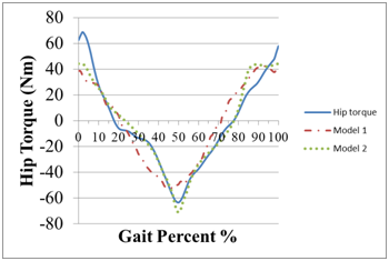
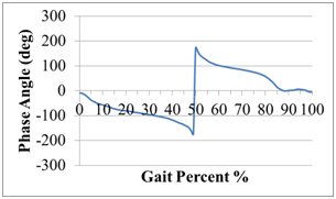
Data from Whittle11 has been digitized to determine an average hip angle and moment. A standard 80 kg subject is used in the modeling and the walking gait is assumed to be at 0.8Hz or a 1.25 second gait cycle. The angular velocity and acceleration were determined using numerical differentiation from the standard biomechanics data. The moment or torque data is modeled with two different methods. In method 1, a standard impedance model with five parameters is used to fit the moment data. The angular position, velocity, and acceleration are used as input data, and then the impedance parameters are optimized to fit the moment data. In method 2, a phase based controller is used to model the torque or moment data and four parameters are used to fit the data. A multi-parameter optimization routine in Excel was used to determine the best fit parameters. The phase based controller had a much more superior fit to the moment data, see Figure 1. The phase angle is shown in Figure 2.

Figure 1 The hip torque for an 80 Kg participant is modeled using an impedance model (Model 1) and a phase based model (Model 2). The phase based model is able to better model the V-shaped torque profile. Biomechanics data from [11] is used to test the models.

Figure 2 The hip phase angle as a function of gait percent. A scale factor of 2.09 is used which corresponds to 2*pi*0.333Hz.
Model 1: In this model a standard impedance model was used with parameters that include: Inertia, Damping, Stiffness, Gravity, and an offset value. Equation 3 shows the best fit parameters to the biomechanics data in11 based on an assumed mass, 80kg, and an assumed gait period of 1.25s.
(2)
;(3)
Model 2: In this model, a phase based controller is used to determine the torque or moment data. The sine of the phase angle is used to adjust the amplitude of the oscillations and acts like a bounded negative damping term. The cosine of the phase angle is used to adjust the frequency of the oscillations. It can be used to increase or decrease the frequency of the oscillation. An offset value was used in this case as well. The scale factor for phi was optimized by the Solver routine and a value of 0.33Hz (2.09 rad/s) was used which is lower than the modeled 0.8Hz walking gait cycle. Equations 5 and 6 show the best fit parameters to the biomechanics data in11 based on an assumed mass, 80kg, and an assumed gait period of 1.25 s.
(4)
(5)
(6)
The uniqueness of a phase based controller shown in Model 2 is that one parameter, f, is used to command a torque to the exoskeleton. Experimentally, this time-invariant parameter is calculated in real time using a rate gyro mounted to the thigh. If the user’s motion is not perfectly periodic or slows down and speeds up, the torque command slows down and speeds up. In summary, the robot’s torque command is based on the phase-based controller. In comparison with the impedance controller, the angular position, velocity, and acceleration must be measured and then scaled with the best fit parameters to determine a torque command for the robot controller.
Parameter variation due to changes in weight and speed
Typically, biomechanics data is scaled based on the weight and speed of the user. For example, the weight of the user is changed from 60 to 120Kg. In a second example, the gait data for walking is scaled from a 1.5 second cycle (0.67Hz) to a 0.75 second cycle (1.33Hz). The robustness of the values in Model 1 and 2 were tested to changes in the weight and speed of the hip motion and torque data. It is shown that the phase-based Model 2 is more robust to changes.
Model 2 can be simplified to the following model with a gain, G, a constant phase shift, g, an offset to, and a scale factor, w:
(7)
(8)
The standard biomechanics data in,11 was scaled based on the weight of a user. When the weight was increased from 60 to 120 kg, the gain G increased linearly; g remained constant; w remained constant and the offset to increased linearly. The results are shown in Table 1 under Model 2. Using an impedance model in equation 2, the values for inertia, I, damping, B, stiffness, K, gravity - mgl, and the offset to changed due to weight changes. When the weight was increased from 60 to 120 kg, the inertia I increased linearly; B increased linearly, K increased linearly, gravity increased linearly, and the offset to increased linearly. The results are shown in Table 1 under Model 1. All five parameters are changed as opposed to only two parameters that were changed in Model 2. For Model 2, when the speed was increased from a 1.5 second cycle to a 0.75 second cycle, the gain G was constant; g was constant; w increased linearly and the offset to was constant. The results are shown in Table 2 under Model 2. It is assumed that the weight is 80kg. For Model 1, when the speed was increased from a 1.5 second cycle to a 0.75 second cycle, the inertia I decreased nonlinearly; B decreased nonlinearly, K increased nonlinearly, gravity decreased nonlinearly, and the offset to remained constant. The results are shown in Table 2. In Model 1, four parameters changed in a nonlinear fashion due to speed changes. However in Model 2, only one parameter changed linearly due to speed changes.
Model 1: |
I (kg m2) |
B N/(m/s2) |
K (N/m) |
mgl (Nm) |
to (Nm) |
60 |
0.454 |
0.125 |
86.52 |
4.55 |
-12.21 |
80 |
0.606 |
0.167 |
115.36 |
6.07 |
-16.27 |
100 |
0.758 |
0.209 |
144.20 |
7.58 |
-20.34 |
120 |
0.910 |
0.251 |
173.04 |
9.10 |
-24.41 |
|
|
|
|
|
|
Model 2: |
G |
g (deg) |
to (Nm) |
w (rad/s) |
|
60 |
43.3 |
-80.67 |
10.08 |
2.09 |
|
80 |
57.7 |
-80.67 |
13.44 |
2.09 |
|
100 |
72.1 |
-80.67 |
16.80 |
2.09 |
|
120 |
86.5 |
-80.67 |
20.16 |
2.09 |
|
Table 1 Parameters are adjusted as the weight changes
Model 1: |
I (kg m2) |
B N/(m/s2) |
K (N/m) |
mgl (Nm) |
to (Nm) |
1.5 |
0.873 |
0.198 |
112.76 |
8.732 |
-16.27 |
1.25 |
0.606 |
0.167 |
115.36 |
6.064 |
-16.27 |
1.0 |
0.388 |
0.135 |
117.49 |
3.881 |
-16.27 |
0.75 |
0.218 |
0.102 |
119.15 |
2.183 |
-16.27 |
|
|
|
|
|
|
Model 2: |
G |
g (deg) |
to (Nm) |
w (rad/s) |
|
1.5 |
57.7 |
-80.67 |
13.44 |
1.74 |
|
1.25 |
57.7 |
-80.67 |
13.44 |
2.09 |
|
1.0 |
57.7 |
-80.67 |
13.44 |
2.61 |
|
0.75 |
57.7 |
-80.67 |
13.44 |
3.49 |
|
Table 2 Parameters are adjusted as the speed increases (constant 80 kg)
A hip exoskeleton was designed that can apply hip flexion and extension torques. The torque applied to the user was based on a simplified equation:
(9)
(10)
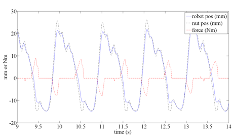
As the user walked, transitioned to running, and ran, a continuous assistive torque was applied based on equations 9 and 10. A constant scale factor was used in equation 10 to simplify the model. A constant offset angle of negative ten degrees was used based on experimental testing. An offset value in Table 1 of -81 degrees was too large and caused resistive forces. Although the values in equations 9 and 10 are different than parameters in Table 1, the same simple model was used to determine a torque command. Experimentally, the angular velocity is measured using a rate gyro and integrated to determine the angular position. A scale factor w is chosen and f is calculated at 500Hz. The torque command is then calculated using equation 9. The applied torque to the user is shown in Figure 3. It is calculated based on the deflection of a spring inside of the hip actuator. The compressed spring pushes on a lever-arm which applies torque to the hip strap. The actuator uses a brushless dc motor and belt drive to rotate a ball screw. The nut position on the ball screw is labeled “nut pos” and measures one side of the spring. The robot position is a measure of the lever arm position attached to the user’s thigh. The lever position measures the other side of the spring. The difference between the “nut pos” and the “robot pos” is the spring deflection which can be converted into a force. The assistive force is multiplied by the lever arm length to calculate an assistive torque in Nm. After weight acceptance, the motor applies a positive 9Nm of torque to extend the hip and assist in the stance phase. As the thigh is flexed during the swing phase, 8 Nm of torque is applied to lift the leg during the swing phase.

Figure 3 The thigh angle moves the lever arm in the actuator. The lever arm position is converted to a linear travel along the ball screw, “robot pos.” The motor adjusts the nut on the ball screw to compress the spring. The nut position along the linear travel is labeled, “nut pos.” The deflection of the spring multiplied by the lever arm is the applied assistive torque in Nm.
The HeSA device provides bi-directional torque support to each hip. It uses a Maxon brushless motor and a transmission consisting of a belt drive and a ball screw. The device is capable of supporting both walking and running gaits. The peak torque for hip flexion and extension is 15Nm. The average electrical power when walking at 1.34m/s was 20 W per motor which is quite low. The total device weight without the battery is 2.27 kg, and the battery weight is 0.68 kg for a standard 24 V, 72Whr Bosch drill battery. Lastly, the hip actuator can disengage from the thigh attachment to allow for extended range of motion. The extended free motion allows the user to flex the hip to ascend stairs and get easily in and out of cars. For more details the reader is referred to references.12-13
Biomechanics data for hip motion is used to model hip torque during walking. Two models were constructed, one based on an impedance structure and one based on a phase angle. The phase based model used less parameters and was more robust to changes in weight and speed. The phase based model uses a phase angle to continuously calculate a hip torque. A simplified phase based model was tested experimentally. The model continuously calculated a hip flexion and extension torque. The torque was applied to the user based on a motor-spring actuator. The controller can be used for walking, stopping, transitioning to running, and running. The phase based model used one parameter less (4 vs. 5) compared to the impedance model and was more robust to changes in the user's weight and speed as evidenced by fewer changes required in the parameters.
Dr. Sugar analyzed the phase-based controller. Dr. Hollander designed, built, and controlled the hip exoskeleton. Dr. Redkar aided in the manuscript writing and research. Drs. Sugar, Hollander, and Redkar are co-investigators on the project.
None.
The authors declare, that there is no conflict of interest.
This work was partially supported by the DARPA grant W911NF-15-1-0162. Any opinions, findings, and conclusions or recommendations expressed in this material are those of the authors and do not necessarily reflect the views of the funding agency.

©2020 Sugar, et al. This is an open access article distributed under the terms of the, which permits unrestricted use, distribution, and build upon your work non-commercially.