Journal of
eISSN: 2377-4282


Mini Review Volume 2 Issue 2
Department of Physics, Shahid Beheshti University, Iran
Correspondence: Seyed Majid Mohseni, Department of Physics, Shahid Beheshti University, GC, Evin, Tehran, 19839, Iran, Tel 9821-29905044, Fax 9821-22431663
Received: February 14, 2015 | Published: April 9, 2015
Citation: Mohseni SM, Mohseni SM (2015) Spintronics as a Neurotechnique. J Nanomed Res 2(2): 00024. DOI: 10.15406/jnmr.2015.02.00025
Understanding the brain as a complex system is the current problem and challenge in multi-disciplinary science. To this end, finding new techniques to touch many un-known mechanisms inside the brain via observations and measurements are circumventing different neurotechniques today. One possible technique toward this purpose is based on sensing the magnetic field of neurons with spintronics devices, given that neurons are sources of magnetic fields. Additionally, correlation of individual neuron’s magnetic field to the magnetic field of many neurons is not very clear. In this paper, we shortly review the application of spintronics as one branch of nanotechnology for neural magnetic field detection. The major spintronics elements that can be implemented for the neural field detection nominated the magneto resistance (MR) will be introduced. Electronic properties of such a device will be reviewed and its technical issues such as magnetic coupling between layers and their materials and thickness dependence toward achieving high sensitive elements will be shortly addressed. Such elements can be implemented to measure the magnetic field of small neuron population down to individual neuron. Potential applications of spintronics elements for neural magnetic field detection toward the completion of the neuroscience will be addressed.
Keywords: Spintronics, Neuron magnetic field, Brain, Magneto resistance, Nano-electronics, Neuroscience
MR, Magneto Resistance; GMR, Giant Magneto Resistance; MTJ, Magnetic Tunneling Junction; TMR, Tunneling Magneto Resistance; MEG, Magneto-Encephalography; SQUIDs, Superconducting Quantum Interface Devices; STT, Spin-Transfer Torque
The term “Spintronics”, analogue to electronics, stands for physical mechanisms based on spin transport in nano-structures. This subject awarded the Physics Nobel prize in 2007 based on finding of the Giant Magneto resistance (GMR) effect.1,2 because of its great potential applications in industry such as magnetic recording media and magnetic field sensors.3-8 Currently, the research about this subject is highly under debate after first experimental observation of spin-transfer torque (STT) effect.9-15 which was theoretically predicted in 1996 .15-19 For example, making nano-magnetic elements for high sensitive and fast sensors, dense and non-volatile memories, signal generators and detectors are desirable.
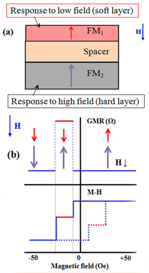
The GMR effect can be observed and controlled in magnetic metallic tri-layers as two ferromagnetic (FM) layers separated via a normal metal (spacer), called spin-valve, as shown schematically in Figure 1a. Thickness of each layer should be around a few nm to prevent the bulk spin scattering in layers. The metal in spacer layer can be Cu or Ag, etc. with a few nm thickness and if the spacer is made of an ultra-thin insulating layer, e.g. MgO, with thickness around 1 nm, the device is called the magnetic tunneling junction (MTJ). This device has much greater magneto resistance changes based on tunneling phenomenon and is called the tunneling magneto resistance (TMR) effect. Hereafter we use the magneto resistance (MR) instead of either of GMR or TMR elements. In the MR stacks, each FM layer can have either in-plane or out-of-plane magnetic anisotropy to make in-plane.13,14 out-of-plane.20 (Figure 1a) and orthogonal.10,12 magnetization counterparts. Magnetic properties of FM layers in this stack may have different switching field. The one which saturates in a small field is called the soft layer and another FM layer which needs larger magnetic field to be saturated is called the hard layer. Because of spin dependent scattering at the interface of FM layer, the resistance of this stack is a function of applied magnetic field. Figure 1b shows the resistance and magnetization of the MR stack as a function of applied magnetic field. In a very simplified picture, when both FM layers have parallel alignments, the resistance is smaller than the case when FM layers are anti-parallel. Therefore, it is possible to design a magnetic field sensor based on the MR stacks. There are some important points that have to be taken into account to design and make a desired magnetic field sensor such as controlled magnetic coupling, hysteresis less, linear, thermally stable and low noise responses.3,7,20 All of these capabilities can be revealed via controlling the magnetic properties of FM layers and physical properties of spacer. Finally, it as to be noted that achieving to such reliable thin multi-layers in MR elements needs accessing to high quality deposition techniques as well as careful growth parameter control.

Figure 1 a. Schematic representation of a spin-valve GMR stack. The soft layer is on top of the device, can be for example NiFe with in-plane anisotropy ot Co/Ni multi layers with perpendicular anisotropy. The hard layer is at the bottom which can be CoFe with in-plane anisotropy of Co/Pd (Pt) multi layers with perpendicular anisotropy, or a mentioned magnetic layers exchange biased to an anti ferromagnetic layer. The spacer layer can be Cu or Ag. The thickness of all layers is less than 10 nm.
b. The GMR and magnetization of the stack against external magnetic field.
The external magnetic field can be produced via an electromagnet or Helmholtz coils to test the MR stack. But, it can be from other sources, for example, the magnetic field generated from magnetic bio-molecules, neurons, magnetic beads, heart, earth, etc. Although, the magnetic field from neurons in the brain, to be detected out-sides of the brain, has very small amplitude, i.e. 100 femto-Tesla. The common magnetometer of the brain, the magneto-encephalography (MEG) system, which is commercially available is made by superconducting quantum interface devices (SQUIDs).21 This magnetometer is very robust and has to work at low temperature. However, despite of its quite good signal to noise ratio and great sensitivity, fabrication of this device is challenging because of requiring high quality thin oxide barrier layer and low temperature equipments test which might be hardly accessible for a researcher who would need to study the brain magnetic field and its correlation with clinical, social, behavioral, and any similar macro-response especially for a long term studies.
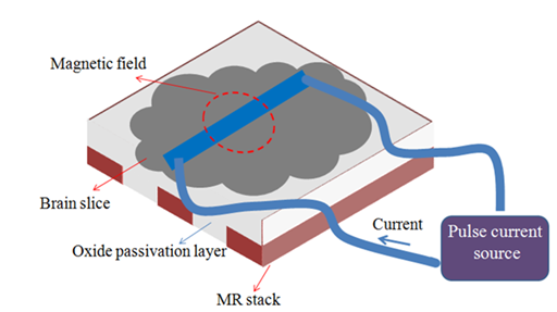
The correlation of magnetic field of each neuron as micro-response in the brain which provides a macro-response magnetic field measurable by MEG system is still under debate in the field of cognitive science, for example.22 In addition, knowledge about the magnetic field of individual neuron as a micro-response of the brain would be demanding. It is also interesting to control the brain magneto-thermally.23,24 and recognize the magnetic reaction by measuring of individual neuron’s magnetic field (micro-response) and also that of population of neurons (macro-response), all toward completeness of knowledge about the brain as a complex system. To provide accessible equipment for this purpose inside the small laboratories, the spintronics can be helped. It is shown that the magnetic field of the brain of mice can be measured with MR elements.25-28 A few measurement series were successfully carried out, for example, in-vitro actuation and recognition of magnetic field of the small slice of mice’s Hippocampus located on a MR stack, as shown schematically in Figure 2.25,29 Achievements suggest that the resolution of the MR magnetic field detector is good enough to record the neuronal magnetic field after their excitations. To be mentioned that, in such measurements, where there is no gap between the brain and the MR sensor, contrary to the MEG and SQUIDs with the cooling shield as technical limitation, the amount of magnetic field of the adjacent neurons is high, i.e. more than pico-Tesla. Therefore, the integrated MR stack has shown to be supportive for magnetic field measurement of neurons. A brief recipe for fabrication of the MR stack can be as follows. The multi-layer stack is first grown by either of sputtering or evaporation techniques on a clean Si/SiO2 substrate. After the deposition, arbitrary shape of the MR stack and its contacts can be fabricated via standard lithography technique (deposition of photoresist, UV exposing of a pattern, washing in developer, dry etching, cleaning the rest of photoresist/ashing) followed by deposition of the passivation (oxide/insulator) layer at the end. The sensitivity of such MR stack can be furthermore enhanced by adding a flux-guide soft magnetic layer to decrease the noise and increase the sensitivity down to pico-Tesla.29

Figure 2 Schematic procedure of the fabricated MR stack array passivated with insulating layer. The mice brain slice was positioned on top and for actuating the brain, a current where passed through a wire inside the brain slice and a magnetic field can be generated. The MR stack is able to detect amplitude and time of the spatiotemporal induced magnetic field right after actuation.
Finally, it has to be mentioned that neural field detection was carried out with a pulse field actuation and the neurons relaxation amplitude and time were recorded.25-29 Such techniques require more attention for future measurements and analyses from clinical points of view.
In the MR stacks including tri-layer, the resistance can change based on any applied magnetic field which makes such nano-structures as remarkable tools for detecting the magnetic field from the neurons. There are important questions about the magnetic field generated by individual neuron and its correlation between the fields generated by many neurons as the final magnetic field that MEG measures. Because the brain is an extremely complex system, finding the answer would be helpful progress toward combination of nanotechnology and cognitive science. The next processes can be characterizing the magnetic field of individual neuron inside a seek brain, while sending drugs to the brain, when actuating the brain with different mechanisms such as light, electric field, ultra-sound, etc toward completion of the neurotechniques. It is also possible like what has been recently done in opt genetics studies.30-32 the MR stack fabricated on a probe needle to be inserted inside a mice brain to detect in vivo the magnetic field during different actuations and reactions. In addition, as the spintronics knowledge is developed in STT devices, it would be great to implement similar measurement with more dynamical properties to study the dynamics of neural field activity. Finally, we insist that the spintronics devices are highly promising for application in neuroscience studies.
Support from Iran National Science Foundation (INSF) is gratefully acknowledged.
None.

©2015 , et al. This is an open access article distributed under the terms of the, which permits unrestricted use, distribution, and build upon your work non-commercially.