Journal of
eISSN: 2373-6437


Research Article Volume 12 Issue 1
Anesthesiologist, Pain Fellow MD-FIPP, Azargan Pain Clinic, Iran
Correspondence: Helen Gharaei, Anesthesiologist, Pain Fellow MD-FIPP, Azargan Pain Clinic, Vanak Sq, North Gandi St, Sanaie St, No 26, 1st flour, Tehran, Iran
Received: December 23, 2019 | Published: January 22, 2020
Citation: Gharaei H. A novel ultrasound guided approach for lumbar periradicular injections with investigating the radicular artery nearby (IRAN) technique. J Anesth Crit Care Open Access. 2020;12(1):24?28. DOI: 10.15406/jaccoa.2020.12.00425
The object of this study is to introduce a novel USG approach for lumbar periradicular injections by investigating radicular artery nearby (IRAN) technique and to assess the feasibility and preliminary means by fluoroscopy.
Study design: The USG periradicular injection is performed under real time imaging. An axial scanning view is obtained through identifying the spinous processes, lamina, zygapophyseal joints and transverse processes.
Setting: The curve probe put transversally and the needle site check in axial and sagittal view.
Methods: The IRAN technique was defined by sliding probe a little lower under the facet joint in sagittal plane to view the pulse of nearby radicular artery by Doppler or Pulse Echo. Then spinal needles are advanced with in-plane technique toward the artery until touch the nearby bone.
Results: Fluoroscopy examination confirms that the needle tip is correctly placed under the pedicle along the nerve root and lateral to the pars interarticularis with no intravascular injection.
Limitation: Although searching for small vessels is difficult in cadaver studies, the IRAN technique would be confirmed in the future on Cadaver.
Conclusion: The IRAN technique as a new anatomic landmark allow an easy and corrected periradicular placement of the needle.
Keywords: ultrasound, spine, injection, intervention and radicular artery
Ultrasound as a portable and accessible device has attracted the attention of pain specialists and is now used for spine injections. As spine injection is more difficult compared to other pain injection techniques, it did not find a routine place in practice. But the transforaminal injection(TF) is still challenging and pain interventionists are always searching for new techniques to decrease the chances of intravascular injection .Intravascular injection has always been a barrier when it comes to choosing ultrasound as a sole modality for spine injection.
According to the Article review in 1971, Bogin and Stulin were the first anesthesiologist who used ultrasound to perform the lumbar puncture and central neuraxial intervention.1 Then Cork et al were the first group of anesthesiologists who used ultrasound to locate the landmarks relevant to epidural anesthesia in 1980.2 Currie JM and Wallace DH et al described the neuraxial sonoanatomy and the measurement of the depth in 1984 & 1992.3,4 The utility of the USG for epidural injection (the optimum window, thoracic epidural space, improving learning curve and combining spinal-epidural) was under investigation by Grau et al. This group refer to Doppler imaging as a modality to provide information regards to the position of vessels in the needle trajectory which could help to reduce complications in lumbar spine injection between 2001 to 2004.5‒10 Real-time USG paramedian epidural access with in-plane approach was described in 2009 by Karmakar in HongKong.11
After the epidural space, it was the facet (Z) joint injection which was considered for USG injection by pain interventionists. In 1997, Kullmer K et al. described the USG lumbar Z joint injection12 and the method was later validated with computed tomography-controlled in 2007 by Galiano et al.13 However, lumbar facet nerve injection or lumbar medial branch block was described later by Greher M et al. in 2004 and oblique out -of- plane technique of L5 dorsal ramus was outlined in 2015.14,15
Due to the complexity of TF procedure,it was later started in 2005 and was considered by Galiano K et al.16 who described lumbar TF injection by founding the neural foramen with the in-plane approach in axial view. The technique was then improved by the help of A. Loizides in 2011.17 who described a new in-plane approach in sagittal view by positioning the transducer perpendicularly over the medial part of the respective transverse processes, depicting the hyperechoic inter transverse ligament. Both techniques were in fact TF injection and not periradicular injection.
In particular, the most challenging part of USG lumbar injection is TF injection and although it is briefly discussed by authors, due to its complication of the intravascular injection it is not routinely used. The objective of this study is to introduce a novel USG approach for lumbar periradicular injections by investigating radicular artery nearby (IRAN) technique and to assess the feasibility and preliminary means by fluoroscopy.
The ultrasound examinations and intervention were performed on a standard device with a broadband 9- to 4-MHz curved array transducer. Ultrasound examination of lumbar spine including sonoanatomy before injection is performed in 4 major steps:
Step1
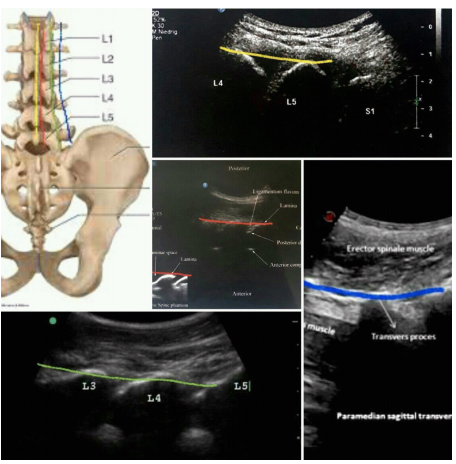
The first step in USG spine injection is to determine the vertebral level. For this propose, put the curve probe longitudinally in the paraspinal space (about 4cm) on the ribs; notice the difference between the rib and transverse process(TP) view. The rib length is longer and the TP are about the same size with hyperechoic tip and finger-like acoustic shadow down (Figure 1). Move probe down towards the sacrum, notice superior articular process of sacrum (SAP S1) at the end and do not mistake it with TP L5.Place the desired level in the middle of the probe and screen (depth about 9cm), then rotate the probe 90 degrees clockwise transversally. By moving the probe upward down, you will get different axial views of the vertebra. For spine injections, you need to look for a clear view of the spinal canal. In this view, spinous process is at the midline and lamia and Z joint (by dedicating its wavy appearance with two layers of superior and inferior articular process ( SAP&IAP) )and TP are more visible laterally (Figure 2).
Step2
The second step is to find four parallel sagittal lines: put the curve probe longitudinally in the midline of the upper lumbar spine to find the horse shape appearance of spinous process; sliding the probe to the sacrum to find the inter spinous process line with a different view of spinous process and a hypoechoic gap which is useful for spinal and epidural injections.
Move probe 1-1.5 cm laterally on paramedian or interlaminar line to find a hypoechoic gap between lamina as a window for epidural block and
then sliding probe on axial scanning 3-4 cm laterally to find the camel hump shape inter pedicular or articular line which in contrast to other lines is continuous without a gap and is useful for confirming the needle tip position in MBB and periradicular block.
By sliding probe on axial scanning more laterally 4-5 cm, the probe would be on TP .By turning the probe 90 degree clockwise longitudinally inter-transverse process line will become visible in sagittal plane with a widen hypoechoic gap between TP which is most useful for vertebral counting (Figure 3).

Figure 3 Sagittal scanning of the spine on spinous processes (yellow line), interlaminar line (red line), inter pedicular line (green line) and inter transverse line (blue line).
Step3
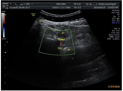
Put the probe transversally on desire lumbar level, then sliding it laterally in axial plane over the Z joint. By sliding and tilting probe a little lower in sagittal plane, search for the pulse of artery under the Z joint by Doppler or the Pulse- Echo method. Measuring the depth of skin to artery for estimating distance to goal (Figure 4).

Figure 4 Doppler axial scanning of the pulse of nearby radicular artery (RA, red dot) under the Z joint.
SP, spinous process; IP, injection point **; TP, transverse process.
Step4
With the in-plane technique, a spinal needle is advanced under real-time scanning towards the artery until touching the nearby bone. If the needle is not able to touch the bone at the estimated depth, the needle might be in intervertebral foramen (IVF), so push the needle out and redirect it. Then turn probe longitudinally 90 degrees clockwise on inter pedicular line or inter transverse line to confirm its position under transverse process. One ml of contrast agent was subsequently injected under live fluoroscopy to rollout intravascular injection. Needle site also confirm in lateral fluoroscopy (Figure 5,6).
Fluoroscopy examination confirms that the needle tip is correctly placed under the pedicle along the nerve root in AP & lateral fluoroscopy with no intravascular injection. Although in cadaver studies, searching for vessels is difficult, I hope the IRAN technique would be confirmed in future on Cadaver.
The most common method for diagnosing the radicular pain is selective nerve root block that is characterized by the diffusion of injections along the nerve root but not the epidural space as opposed to the TF injection that is confirmed by injection into the epidural space. Although most of the times both blocks are used interchangeably.18,19 The TF injection is still challenging and pain interventionists are always searching for new techniques to decrease the chances of intravascular injection. The intervertebral foramen (IVF) is a hole located between the two adjacent vertebrae that allow communication between the spinal canal and the external area. Although, it is used as a pathway through the spinal nerve roots, vascular structures follow the same path. Knowledge of these vessels and the origin of the feeding arteries are essential for interventional procedures.
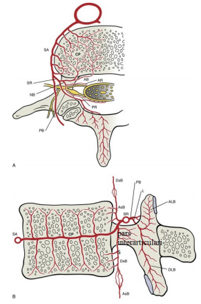
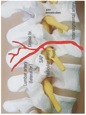
The underlying vascular structure consists of two separate segmental vessels left and right that arise from the posterior surface of the aorta. These lumbar arteries divides into several branches reaching the level of the IVF. Three medially directed branches arise from the spinal ramus branch of the lumbar segmental artery (SA). These are the anterior spinal canal branch (AB), the posterior spinal canal branch (PB)and the neural branch (NB) which are separated into anterior and posterior radicular artery (AR& PR) that feed the ventral and dorsal roots (Figure 7). Some radicular arteries regress while others grow larger. The radicular arteries that are very small become lost along the roots before reaching the spinal cord.20 Radicular arteries can sometimes be replaced functionally by segmental radiculomedullary arteries. However, unlike those arteries, radicular arteries do not form anastomosis with the anterior or posterior spinal arteries. What we really see in IRAN technique out of foramen (under pedicle and lateral to the pars interarticularis) is SA or SR and not RA (Figure 8).

Figure 7 Arterial supply to a lumbar vertebra, horizontal section (A) and midsagittal section (B) SA, segmental artery; SR, spinal ramus; AB&PB, anterior & posterior branches; NB, neural branch; AR&PR: anterior & posterior radicular arteries; AsB &DsB, Anterior branch ascending &descending branches; L, laminar; ALB&DLB, laminar ascending &descending branches. .

Figure 8 Schematic representation of nerve root and accompanying artery on the pars interarticularis.
The most important radiculomedullary is the Adamkiewicz (AK) artery which are found mainly in the region of the dorsolumbar junction. The AK is sometimes called greater radicular artery of AK, however it is in fact a segmental artery. The location of AK within the IVF is important. Neurologic deficit can occur when the blood supply to the spinal cord compromise and presented as anterior spinal artery syndrome. Spinal cord ischemia and stroke occurring during the TF injection may result from the arterial embolization with air or particulate steroids or from direct vessel injuries such as spasm, laceration, and dissection.21
TF injection is performed using 3 techniques: classical or supraneural (subpedicular), retroneural and retrodiscal or infraneural techniques. In the classical or sub-pedicular technique, the needle insertion is under the pedicle and above the SAP through the safe triangle area. In the retroneural technique (periradicular or selective nerve root block), needle insert lateral to lamina and lower to TP along the lateral border of the nerve and in the kambin's triangle technique the needle position is lateral to the upper two-thirds of the SAP (supra-pedicular) (Table 1).
Transforaminal injection approaches |
Needle tip |
Goal |
Contrast spread |
Classical or supraneural (subpedicular ) |
under the pedicle and above the SAP |
Safe triangle area |
Irregular line pattern along |
Retroneural ,periradicular or selective nerve root block |
lateral to lamina and lower to transverse process |
Lateral border of the nerve |
Irregular line pattern along |
Retrodiscal or infraneural techniques |
lateral to the upper two-thirds of the sap (supra-pedicular) |
Kambin's triangle |
Irregular line pattern in lateral border of the intervertebral disc which extend into the anterior epidural |
Ultrasound guided IRAN technique |
lateral to lamina and lower to transverse process, just lateral to the pars interarticularis |
Nearby radicular artery |
Irregular line pattern along |
Table 1 Comparison of Transforaminal injection approaches
The safe triangle zone is in fact not safe. The kambin's triangle method seems to be safer but recently, there have been prospective studies showing a relatively high rate of inadvertent intradiscal injections with this technique. There are also concerns about intrathecal and vascular injections during this performance.22,23 Retroneural approach may help to avoid intravascular injection due to placing the needle lateral to the exiting nerve root and farther from IVF. There is a fluoroscopic retroneural approach where the needle is placed posterior or posteroinferior within the foramen and is relatively parallel to the dorsal root ganglion or nerve root at the upper portion of the SAP, closer to its lateral edge.24 It should wrap around the upper half of the SAP and the line formed between the lateral at the midpoint of the superior and inferior pedicles. The preganglionic approach is another retroneural approach and the objective is to position the needle tip which is medial and inferior to that used in the classic approach, just lateral to the pars interarticularis on the oblique fluoroscopy view. There is no significant correlation between pain relief and needle tip position retroneural or subpedicular, extraforaminal, junctional or foraminal and the success rate is not dependent upon the distance between the needle tip and the nerve root.25,26
The IRAN technique is an example of the retroneural or periradicular technique which is done under USG and the needle tip is nearby radicular artery and far from it, lateral to lamina and lower to transverse process.
Even though the vessels are visible by ultrasound, it is advisable to inject a contrast agent at the end of the IRAN procedure and take a live or real-time fluoroscopy to rollout the intravascular injection. (Intravascular contrast injection is typically not seen on single shot fluoroscopy imaging because the contrast material is rapidly diluted in the bloodstream). In case of do not access to fluoroscopy, first inject a test dose (e.g. normal saline) and look at its distribution with Doppler on the ultrasound screen (if there wasn't any distribution, the injection may be intravascularly) then inject local anesthetic and after confirming patient alertness inject the non-particulate steroid. Although searching for small vessels is difficult in cadaver studies, but this is a limitation of this study and I wish the IRAN technique would be confirmed in the future on Cadaver.

©2020 Gharaei. This is an open access article distributed under the terms of the, which permits unrestricted use, distribution, and build upon your work non-commercially.