In the subject work a multi tubular reactor with provision for internal heat recovery is proposed for storing of natural gas (NG) in adsorbed form using highly micro porous adsorbent such as activated carbon and subsequent discharging. The proposed reactor is suitable for large scale storage of NG without any external heating and cooling. The water present in the shell side of the shell-and-tube type reactor absorbs heat during charging keeps the tubes packed with adsorbent relatively cooler and releases heat during discharging of NG thereby accelerates the charging and discharging process. The transient behaviour of the proposed system is predicted by numerically solving the corresponding heat and mass transfer equations. Simulation is being carried out for constant pressure (35 bar) charging and constant pressure (1 bar) discharging till a stable cycle is attained. The novelty of the system lies in the fact that the proposed reactor does not need any external energy input, at the same time offering high delivery capacity. Moreover, the system works under pressure swing principle. Parametric studies as well as second law analysis are presented to identify suitable water circulation rates and initial fluid temperature by minimizing net entropy generation.
Keywords: natural gas storage, energy storage, heat and mass transfer, shell and tube, entropy
Natural Gas (NG) is an inexpensive and clean burning fuel. Hence it has attracted the attention of the policy makers in several countries including China and India for its commercial and industrial use.1 However the challenge of safe and compact storage of NG, due to its low energy density need to be addressed before it can be considered for its large scale use in various portable as well as stationary applications. Among the various storage methods available at present such as compressed natural gas (CNG), liquefied natural gas (LNG) and adsorbed natural gas (ANG), the last option (i.e., ANG) offers many benefits interalia safety, design flexibility of the storage tank, low cost etc..2–7 On the other hand the exothermic and endothermic nature of the adsorption and desorption processes with poor transport properties of the adsorbent particles strongly affects the storage and delivery capacity, thereby reducing the driving range of the vehicles substantially, when ANG is used for transport applications. Chang & Talu7 observed a reduction of 35% storage capacity under adiabatic conditions, as compared to an isothermal charge case. In view of the importance of effective heat and mass transfer, many researchers have carried out studies on heat and mass transfer management of the adsorbent bed undergoing charge and discharge cycles. Different heat transfer enhancement techniques such as provision of internal and external fins, insertion of tubes carrying hot water during desorption, multi cylinder ANG tanks with centrally located heat pipes etc. have been proposed.8–17 Studies are also carried out on prediction of the structural, thermo-physical as well as adsorption characteristics of different activated carbons.18,19 Several cities in India and elsewhere have already introduced CNG based buses and other vehicles. There is also a growing interest in running locomotives using NG. Attempts were also made to use natural gas for fishing boat engines.20 An important requirement of large scale storage of NG is seen in the filling stations. In most of these applications, design of ANG reactors with fast charge/discharge characteristics is essential. Since charging is exothermic and discharge is endothermic, use of suitable thermal energy storage system can minimize the costs associated with cooling and heating during charge-discharge processes. However, no studies on such ANG systems are available in open literature. In this paper a shell and tube type reactor suitable for large scale storage of NG is considered. Due to high storage pressure (35 bar) of NG, the adsorbent (Activated carbon) and adsorbate (NG) are confined to the tube side, while the external fluid (water) flows on the shell side in a closed loop. The water on the shell side acts as an energy carrier absorbing heat of adsorption from the bed during charging and supplying the same to the bed during discharging. A mathematical model based on reactor heat transfer and kinetics is developed to simulate the performance of this ANG system under variable charge-discharge conditions. Effects of important design and operating parameters on the performance of the reactor are studied in detail so as to suggest means for controlling the system performance. It is expected that this study will be useful in the practical design and evaluation of ANG systems for large scale storage of NG.
Ar Area ratio
As Bundle cross flow area, m2
B Baffle spacing, m
CL Tube layout constant
CTP Tube count calculation constant
Ds Shell diameter, m
De Equivalent diameter of the shell, m
E Characteristic energy, J/mol
Ea Activation energy, J/mol
f Friction factor
Gs Shell side mass velocity, kg/ (m2 s)
Kso Pre exponent constant for equation of kinetics of sorption, s-1
Lt Length of the tube, m
˙mf Circulation rate, kg/s
M Molecular weight, kg/ k mol
Nb Number of baffles
Nt Number of tubes
n Index of isotherm equation
Pt Tube pitch, m
PR Pitch ratio
Qd Volumetric delivery capacity, m3/m3
q Concentration, kg/kg
r Radius of adsorbent bed, m
Res Shell side Reynolds number
S Entropy, J/K
s Specific entropy, J/(kg K)
T Temperature, K
t Time, s
U Overall heat transfer coefficient, W/ (m2 K)
v Specific volume, m3/kg
Wo The limiting volumetric adsorbate uptake, m3/kg
Wp Pumping work, J
y Mass ratio, kg/kg
Z Compressibility factor
ΔH ε Isosteric heat of adsorption, J/mol
ε Porosity
α Thermal expansion coefficient, K-1
λ Thermal conductivity, W/(m K)
μ Viscosity, N sec/m2
a Adsorbed
avg Average
b Boiling, bed
c Cycle, change
d Delivery
cr Critical
dis Discharge
eff Effective
eq Equilibrium
f Fluid, fin, final
g Gas
gen Generated
gr Graphite
i Inner, initial
net Net
o Outer
p Particle
r Radial
s Saturation, specific, steel, solid
t Total, tube
w Wall
Physical model
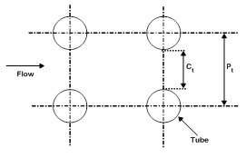
Figure 1 shows the schematic of the ANG storage system for large scale storage which consists of a shell and tube type ANG reactor, NG gas cylinder, two pressure control valves (PCV) and a pump. Through the 3-way valve, the ANG reactor is connected to the gas cylinder during charging process and discharge which is carried out at 1 bar pressure regulated by a pressure control valve. The water present inside the shell is circulated for improving the heat transfer coefficient by using a pump, without any external heating or cooling. The system behaves as a closed system with shell side filled with water. The shell is assumed to be completely insulated from outside and no renewal of the water inside the shell is considered. The water absorbs heat during charging period and supplies the stored heat to the bed during the discharge time. NG is charged into the reactor through the header and subsequently from the header to the tubes through the central porous filter. As shown in Figure 2, square tube layout is considered here. Figure 3 shows the sectional view of the tube with annular portion between the tube wall and inner porous filter filled with a homogeneous mixture of activated carbon and enhancement material (graphite). For the purpose of simulation, the reactor is assumed to be charged with NG at a constant inlet pressure of 35 bar till the bed concentration reaches 0.2 kg/kg. After the charging process is over, the tank is isolated from the supply tank, then it is allowed to reach equilibrium at the corresponding fluid temperature, and subsequently after reaching equilibrium the discharge process is initiated and continued by withdrawing NG at a constant downstream pressure of 1 bar till bed concentration reaches 0.03 kg/kg. After the above process the delivery valve is closed and the bed is allowed to reach equilibrium. To limit the process time and to get a stable cycle the maximum and minimum concentrations are constrained to 0.2 kg/kg and 0.03 kg/kg respectively.
To simplify the mathematical model, the following assumptions are made:
Tube side heat and mass transfer
Energy equation: The energy equation, derived by writing energy balance equation for an annular differential control volume of the adsorbent bed is given by:
(ρC)eff∂T∂t=1r∂∂r(rλeff∂T∂r)+1k(1−εt)ρsΔHM∂q∂t............... (1)
The effective heat capacity and thermal conductivity of the ANG bed (consisting of a homogenous mixture of adsorbent particles, graphite powder and NG in the void space) are given by:
(ρC)eff=1k((1−εt)ρsCs+εtρgCp,g+(1−εt)ρsCgry+(1−εt)ρsqCa)................. (2)
λeff=1k((1−εt)λs+εtλg+(1−εt)yρsρgrλgr).............. (3)
k=1+(1−εt)y(ρsρgr)
Where,k=1+(1−εt)y(ρsρgr) ; and y=mgrms.................. (4)
“k” is the parameter which accounts for the presence of the graphite powder in the adsorbent bed.
The total porosity of the adsorbent bed is given by:9
εt=εb+(1−εb)εp............... (5)
The specific heat of the adsorbed phase is given by [18]:
Ca=Cp,g(P,T)+α2(1−n)n2ETM(lnWoqeqva)(1−2n)n−2Rg................... (6)
Adsorption isotherm: Among the different isotherm models like Langmuir, Toth , D-R and D-A available in the literature, The Dubinin -Astakhov (D-A) isotherm model is chosen here to calculate the equilibrium adsorption capacity. The D-A isotherm model accounts for surface heterogeneity and also fits well at high pressure.
The D-A isotherm equation is given by:21
qeq=W0vaexp[−{RuTEln(PsP)}n]..................... (7)
Where va is the specific volume of the adsorbate in the adsorbed phase given by:22
va=vbexp[α(T−Tb)]............... (8)
vb is the specific volume of the saturated liquid adsorbate at the normal boiling point, Tb and is the thermal expansion coefficient of the adsorbed phase. The temperature
Dependency of can be approximately expressed as given in equation (9) from the definition of thermal expansion coefficient.23
α=1T..................... (9)
Ps is the saturation vapour pressure at the adsorption temperature. When adsorption occurs above the critical temperature, Ps is given by:18
Ps=(TTcr)2Pcr........................ (10)
Equation of kinetics of sorption: The driving force for adsorption rate of gas molecules in adsorbent bed is given by the kinetic equation:24
dqdt=Ksoexp(−EaRuT)(qeq−q)..................... (11)
Initial conditions: Initially (time, t = 0) the reactor is at ambient temperature (308 K) and the bed pressure is same as ambient pressure (0.1 MPa).
T(r,0)=Ti ........................ (12)
P(r,0)=Pi........................ (13)
q(r,0)=qeq(Pi,Ti)............... (14)
ρg(r,0)=f(Pi,Ti)..................... (15)
The charging process is continued till the average concentration reaches 0.2 kg/ kg under constant pressure (35 bar) charging condition. After charging process is over the reactor is isolated from the supply tank and is allowed to reach equilibrium state without any further supply of NG from outside. Then the bed is subjected to constant pressure (1 bar) discharge condition till the average bed concentration drops to 0.03 kg/kg. After the discharge process the bed is still allowed to reach equilibrium at corresponding fluid temperature.
Tube side boundary conditions: Assuming adiabatic condition at the inner radius of the adsorbent bed,
∂T∂r(ri,t)=0.................... (16)
At the outer radius of the adsorbent bed
−λeff∂T∂r=hi(T(ro,t)−Tt(t)).......................... (17)
The mass averaged bed temperature and concentration Tavg and qavg are defined as:
Tavg(t)=∫rori(ρC)effT rdr∫rori(ρC)effr dr..................... (18)
qavg(t)=∫roriq(1−εt)ρs r dr∫rori(1−εt)ρsr dr......................... (19)
Energy balance for the tube:
(mC)tdTtdt=hi Ai(T(ro,t)−Tt)−ho Ao (Tt−Tf)....................... (20)
Where Ai and Ao are the inner and outer area of a single tube respectively.
Initial condition for the tube:
Tt(t = 0) =Ti ..................... (21)
Shell side calculations: The energy balance for the shell side fluid can be given by:
(mC)fdTfdt=ho Ao,t(Tt−Tf)...................... (22)
Where the total outside heat transfer surface area based on outside diameter of the tube is given by:
Ao,t=πdoNtLt............... (23)
Shell side heat transfer coefficient calculation: The length of the tube is fixed at 2.5 m then number of tubes is calculated from the mass of the adsorbent using the following expression:
Nt=k ms ρs (1−εt)...................... (24)
Shell diameter is calculated using following expression:25
Ds=0.637√CLCTP[Ao,tPR doLt]0.5............................ (25)
Where:PR=Ptdo .......... (26)
Equivalent diameter of the shell is defined as:
......................... (27)
As=DsCtBPt
Bundle cross flow area:
De=4(P2t−πd2o4)πdo................................. (28)
Where baffle spacing B is taken as 0.6 Ds and .25
Shell side mass velocity:
Gs=˙mfAs..................................... (29)
The shell side heat transfer coefficient for external fluid is calculated using McAdams correlation given below:25
hoDeλf=0.36 (DeGsμf)0.55(Cp,fμfkf)1/3(μfμw)0.14
(for 2×10³<Res=GsDeμf<1×10⁶ )................ (30)
For no circulation case it is assumed that:
hoDeλf=1 ................. (31)
In the above correlation μw is the viscosity of external fluid calculated at wall temperature and μfis the viscosity of external fluid calculated at mean fluid temperature.
Shell side pressure drop calculation: The pressure drop on the shell side is calculated by the following expression:25
ΔPs=fG2s(Nb+1)Ds2ρfDeϕs.......................... (32)
Where: ϕs=(μf/μw)0.14, Nb=(Lt/B)−1................... (33)
(Nb+1) is the number of times the shell fluid passes the tube bundle and Nb is the number of baffles.
The friction factor f is calculated from
f=exp(0.576−0.19ln (Res))
for 400<Res=GsDeμf≤1×10⁶ .................. (34)
The energy input to the pump required for the circulation of water for a complete cycle is calculated using following formula:
Wp =tcyc∫o˙mfΔpsρf dt............................. (35)
To simplify the calculation it is assumed that the power input to the water by the pump got dissipated by friction and an equivalent amount of heat i.e ˙Qpis lost to the surrounding. So the net energy input to the system is zero. Based on this assumption it can be written that
˙Qp =˙Wp......................... (36)
All the thermo physical and transport properties of the external fluid (water) are taken from NIST Standard Reference Database 23, Version 9.0.
The performance of the ANG system is indicated in terms of the delivery capacity and effective delivery capacity, given by:
Qd=1.5×((qavg,i,dis−qavg,f,dis)ms+mg,i,dis−mg,f,dis)Vt............................. (37)
Qd,eff=Qd VtVshell.......................... (38)
Where Vt is the total tube volume and qavg,i,dis is the average concentration at the start of discharge and qavg,f,dis is the average concentration at the end of discharge. Similarly mg,i,dis and mg,f,dis are the gas mass in the gas space at the beginning and end of desorption respectively. The constant ‘1.5’ is the specific volume of the gas calculated at standard temperature and pressure (STP) (T = 298 K, P = 101.325 kPa). Qd,eff is the effective delivery capacity based on the shell volume.
Second law analysis for the ANG bed for complete charge discharge cycle
The net entropy generated during both charging and discharging of an ANG bed is calculated using entropy balance equation.
dSbdt+dStdt+dSfdt=˙Sg,in−˙Sg,out+˙Sgen,net−˙QpTamb............................ (39)
tcycle∫0˙Sgen,netdt=tcycle∫0dSbdtdt+tcycle∫0dStdtdt+tcycle∫0dSfdtdt+tf∫tch˙Sg,outdt−tch∫0˙Sg,indt+tcycle∫0˙QpTambdt................. (40)
Sgen,net=ΔSb+ΔSt+ΔSf+Sgas,out−Sgas,in+˙QpTamb........................... (41)
The entropy change of the adsorbent bed comprising of different parts can be expressed as:
ΔSb=ΔSs+ΔSgr+ΔSg+ΔSa....................... (42)
The change in entropy of the adsorbent (activated carbon) for a complete but stable cycle is expressed as:
ΔSs=ms,tCsln(Tavg,fTavg,i).......................... (43)
Similarly the entropy change of the enhancement material (graphite), methane in gaseous as well as in adsorbed form are expressed as given in equations 44, 45 and 46 respectively.
ΔSgr=ms,tyCgrln(Tavg,fTavg,i)................... (44)
ΔSg=mg,fsg(Pf,Tavg,f)−mg,isg(Pi,Tavg,i)...................... (45)
ΔSa=ms,tqisa,i−ms,tqfsa,f......................... (46)
sa,i=s(Tavg,i,Pi,qeq,i) and sa,f=s(Tavg,f,Pf,qeq,f).............................. (47)
The specific entropy of the adsorbed phase can be expressed as:18
sa (T,P,qeq)=T∫ToCp,aT dT−P∫PoαvadP−qeq∫0qva{αPnln (PsatP)/ln(Woqva)} dq ............... (48)
In the above equation the specific heat of the adsorbed phase, CP,a is replaced by:18
CP,a=CP,f+α2(1−n)n2ETM ln (Woqva)1−2nn For (T < Tcr)............... (49)
for (T CP,a=CP,g(P,T)+α2(1−n)n2ETM ln(Woqva)1−2nn−2Rg Tcr).................. (50)
For the integration in equation 45, To is taken same as the normal boiling point of methane (111 K) and Po is the normal atmospheric pressure 101.325 kPa. At this reference state the entropy of the adsorbed phase as well as the gaseous phase are assumed to be zero.
The change in entropy of the reactor wall as well as shell side fluid can be expressed as:
ΔSt=mtCtlnTt,fTt,i........................ (51)
ΔSf=mfCflnTf,fTf,i............ (52)
Entropy in and out during the gas exchange process are evaluated using the following expressions:
Sg,in=tch∫0˙mg,insg,indt;Where:sg,in= sg (Pch,Ti) ..................... (53)
Sg,out=tf∫tch˙mg,outsg,outdt where:sg,out=sg(Pdis,Tavg) ........................... (54)
˙mg,in=Vg,tdρgdt+ms,tdqdt......................... (55)
˙mg,out=−ms,tdqdt−Vg,tdρgdt........................ (56)
The results are obtained for the input values given Table 1.9,25,26 Due to lack of availability of kinetic data of methane and Maxsorb III pair for linear driving force (LDF) model, the kinetic data for the present study are obtained by carrying out non-linear regression analysis using the experimental adsorption uptake data of Rahman.26 The governing differential equations for mass and energy balance of the adsorbent bed have been solved by using a fully explicit finite difference method (FTCS - Forward in Time and Central in Space scheme).The grid size and time step are fixed based on the stability criteria and grid independence test. If not mentioned the tube length, pitch ratio are assumed to be fixed at 2.5 m and1.25 respectively.
Adsorbent |
MAXSORB III |
Mass of the adsorbent (ms,t), kg |
250 |
Density of the solid adsorbent (ρs), kg/m3 |
2200 |
Specific heat capacity of the adsorbent (Cs), J/(kg K) |
1375 |
Thermal conductivity of the solid adsorbent (λs), W/(m K) |
0.243 |
Total porosity (εt) |
0.8 |
Charging pressure (Pch), MPa |
3.5 |
Discharge pressure (Pdis), MPa |
0.1 |
The limiting volumetric adsorbate uptake (Wo), m3/ kg |
1.618×10⁻³ |
Characteristic energy (E), J /mol |
5257.5 |
The adsorbent’s surface-structural heterogeneity factor (n) |
1.33 |
Constant (Kso), s-1 |
11×10-2 |
Energy of activation (Ea), J/mol |
6000 |
Isosteric heat of adsorption ΔH, kJ/k mol |
16000 |
Inner radius of adsorbent bed (ri), m |
0.003 |
Outer radius of the adsorbent bed (ro), m |
0.01301 |
Outer radius of the tube (rt), m |
0.01428 |
Tube material |
Copper |
Tube layout constant, (CL) |
1 |
Tube count calculation constant, (CTP) |
0.93 |
Length of the tube, (Lt), m |
2-3 |
Enhancement material |
graphite |
External cooling/heating fluid |
water |
Circulation rate ˙mf , kg/sec |
0 -100 |
Ambient temperature (Tamb), K |
308 |
Initial temperature of water K |
288-308 |
Contact conductance between bed and the wall (hin), W/ (m2 K) |
1000 |
Initial bed temperature (Ti), K |
308 |
Percent mass of graphite (y) |
10% |
Thermal conductivity of graphite (λgr), W/m K |
388 |
Specific heat of graphite (Cgr), J/kg K |
1423 |
Density of graphite (ρgr), kg/m3 |
2260 |
Table 1 Input for the simulation
Effects of water circulation rate
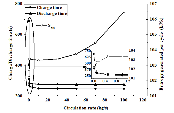
Figure 4 depicts the variation of the charge-discharge time as well as net entropy generated for a stable and complete cycle with circulation rate of the fluid present inside the shell. One case was also studied for no circulation of the fluid assuming Nusselt number to be one. From the figure it is evident that from no flow to circulation rate upto1 kg/s there is a sharp drop in charge as well as discharge time. However, increase in circulation rate beyond this does not improve the performance significantly, but increases the net entropy generation.
Figure 5 shows the variation of the pumping work with circulation rate. From the figure it is clear that from 10 kg/s to 100 kg/s there is a sharp rise in the energy input to the pump but up to 10 kg /s circulation rate the pumping work is almost negligible. So looking forward to the above explanation the circulation rate is kept fixed at 10 kg/s for stable and optimum performance.
Figure 6 shows the variation of the maximum and minimum bed temperature with circulation rate of the shell side fluid. The figure clearly shows that maximum and minimum bed temperatures do not vary much for flow rate beyond 10 kg/s. It is clearly visible in the figure that the maximum temperature of the bed is much below the boiling point of the water and minimum temperature is above the freezing point. So water can be safely used as the shell side fluid.
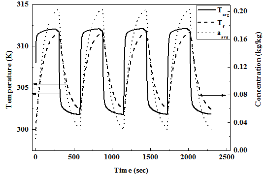
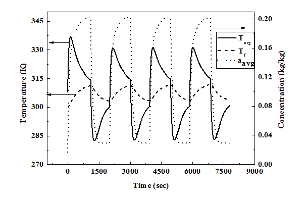
Figures 7, Figures 8 show the temporal variation of the average bed temperature, average bed concentration and fluid temperature for multiple stable cycles for circulation rate of 10 kg/s and no circulation case respectively. During charging the bed temperature rises initially due to its exothermic nature and low heat extraction rate. Towards the end of the charging process the bed temperature starts dropping due to lower heat generation rate compared to extraction rate as the bed gets almost saturated thereby reducing the adsorption rate. It is also seen that the fluid temperature continuously rises during charging because it takes heat from the adsorbent bed but the rate of rise reduces towards the later part of charging process. If we compare no flow with flow case the maximum temperature reached in no flow case is nearly 20 K more than that of flow case. Also the temperature drop towards the end of charging is more for no flow case compared to flow case due to higher temperature difference between the bed and fluid. In spite of higher temperature drop the bed temperature at start of discharge will be higher for the no flow case which favours the discharge process compared to that with flow case. Similarly during discharge process initially the bed temperature drops sharply due to endothermic desorption process but towards the end of desorption the rate of temperature fall reduces due to the same reason as explained earlier.
Effect of initial fluid temperature
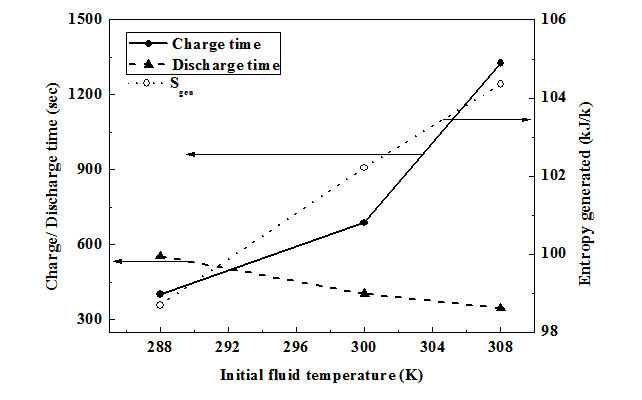
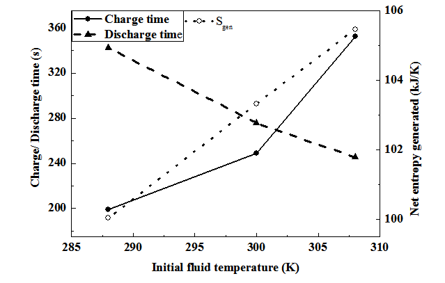
Figures 9, Figures 10 shows the variation of both charge and discharge times as well as net entropy generation with initial temperature of the fluid for no circulation and circulation cases respectively. As the initial temperature of fluid increases the heat transfer from the bed to fluid decreases during charging due to lower potential for heat transfer there by increasing the average bed temperature and reducing adsorption rate. Due to decrease in the adsorption rate, the time for charging increases. On the other hand higher initial fluid temperature results in higher fluid temperature during discharge. As desorption is an endothermic process, higher fluid temperature improves the heat and mass transfer and thereby reduces the discharge time. So, a higher initial temperature of the fluid results in increase in charging time and reduction in discharge time with rise in the net entropy generated. The difference in the entropy generation is mainly due to difference in the temperature of the gas during charging and discharging for different initial fluid temperatures. From the figures it is clear that the effect of the initial fluid temperature is more severe on charging time compared to discharge time both for circulation and no circulation cases. However the effect is more pronounced in no circulation case. So it is found that the cycle time (charge discharge) decreases by 600 s for no circulation case for decrease in initial.
Fluid temperature from 308 to 300 K, but further decrease in fluid temperature to 288 K, decreases the cycle time by nearly 100 s only. So keeping this in mind the optimum initial temperature of the fluid can be fixed at 300 K.
A mathematical model is formulated to design and simulate a shell and tube type of reactor for large scale storage of NG without any external heating and cooling. The reactor behaves as an energy storing device and absorbs the energy during charging and gives up the same during discharge there by helps in accelerating charge and discharge process. Design and simulation are done for both charging at constant pressure of 35 bar and discharging at constant pressure of 1 bar. The study yields typical design dimensions of the reactor and also the designed reactor is simulated for various design and operating conditions. From this study it is found that for a 2.5 m long and 0.9 m shell diameter reactor with 460 tubes each of 2.5 m long, it is possible to accommodate 250 kg of adsorbent. More over with this design condition it is possible to store and discharge 54 kg of NG with charging/discharging time of 4 to 5 minutes with a circulation rate of 10 kg/s. For the given design the delivery capacity based on total tube volume and effective delivery capacity based on shell volume are found to be 104 V/V and 49 V/V respectively.
None.
The author declares no conflict of interest.
© . This is an open access article distributed under the terms of the, which permits unrestricted use, distribution, and build upon your work non-commercially.