International Journal of
eISSN: 2574-8084


Case Series Volume 7 Issue 4
GenesisCare Radiation Oncology, Mater Hospital, Australia
Correspondence: Gerald B Fogarty, GenesisCare Radiation Oncology, Mater Hospital, 25 Rocklands Rd, Crows Nest, NSW 2065, Australia, Tel 61 2 9458 8050, Fax 61 2 9929 2687
Received: July 15, 2020 | Published: July 24, 2020
Citation: Alcevski B, Shearer T, Yeong Y, et al. Techniques to verify the correct skin areas for biopsy, treatment, recurrence and in-vivo dosimetry using an A4 plastic sheet as template. Int J Radiol Radiat Ther. 2020;7(4):112-118. DOI: 10.15406/ijrrt.2020.07.00275
Introduction
Radiotherapy (RT) is a precise treatment usually given over multiple sessions with millimetre accuracy to the planned target. Patients undergoing RT require verification of the target area prior each treatment. Imaging with kilovoltage X-rays is usually used to verify the treatment volumes of solid internal tumours, but this process is unsuitable for skin cancers as it cannot visualise skin marks. When biopsying or treating skin cancers, there is a chance that other nearby benign skin structures can be confused with the lesion of concern. Templates using transparent sheets have been used to verify the treatment area. We present a series of cases to demonstrate our skin cancer verification technique using the humble A4 plastic sheet protector.
Case series: Case 1 details the use of a plastic sheet template to correctly identify lesions that require biopsy. Cases 2 and 3 describe how templates are used for in-field verification prior to electron and superficial RT treatment, respectively. Case 4 shows how stored templates can be used to quantify recurrence.
Conclusion: For skin cancer planning and verification, the A4 plastic sheet protector is easy to use, reproducible, economical and storable. It serves multiple purposes: to delineate areas of biopsy and treatment, to discover whether a recurrence is in-field or not, and to also verify where in vivo dosimetry should be measured.
Keywords: planning techniques, skin cancer, biopsy, recurrence, radiotherapy, templates, case study, Xstrahl
Radiotherapy (RT) is an established cancer treatment. RT is given in a fractionated manner and the same target aarea needs to be treated with every fraction. In other tumour types, for example lung and brain, this is achieved with frequent imaging with kilovoltage (kV) X-rays (plain X-ray films or computed tomography (CT)), often taken daily throughout the treatment course. These scans are then compared against the planning film or scan to verify that the planned volume is being treated. Australia has the highest rate of skin cancer in the world and its incidence is increasing.1 Radiotherapy (RT) for skin cancer is gaining popularity as a treatment option, especially when tissue conservation will lead to better functional and cosmetic outcomes.2,3 RT modalities and techniques for skin disease are evolving4,5 and offer similar tumour control as other skin cancer treatments.6 Verification of RT treatment to the skin cannot, however, be done with kV scanning as the target area on the skin is unable to be seen in the images. Other methods are needed to verify that the correct area is being treated. Ensuring that the right biopsy report corresponds to the right lesion is another issue with skin cancer. Multiple skin cancers can present amongst a myriad of similar looking but benign skin structures, such as freckles and seborrheic keratoses. This increases the chance that other nearby benign skin structures become confused with the lesion of concern. From early in the history of skin RT, templates using transparent sheets have been used to verify the treatment area. We present a series of cases to illustrate how our department uses the humble A4 size plastic sheet protector as a template and discuss its uses. We hope this information may assist other skin treatment clinicians with lesion verification.
Plastic sheet template technique for biopsy recording
A middle-aged man presented with multiple lesions on the lower leg (Figure 1). Biopsies were needed to see if these were malignant (Figure 1A). Lesions suspicious for malignancy was examined and the extent of the clinical tumour was circled (Figure 1B). A template was then created using an A4 plastic protector sheet. The plastic sheet was laid over the area of interest. The sheet was placed in a position that enabled localised regional surface anatomy to be included. The areas containing the lesions were traced onto the sheet using a black permanent marker to create a template (Figure 1C). Benign visible skin structures within the area of the plastic sheet area were also traced to assist with future localisation (Figure 1D). The finished template shows orientating labels (superior, medial and inferior are visible in this view), a measurement scale bar, and numbers identifying the lesion. Numbering each lesion helps to link biopsies to the proper lesion. As they are taken, biopsies should be labelled with the corresponding lesion number (Figure 1E). The size of the plastic sheet size allows the template to be photocopied onto an A4 piece of paper. This can then be scanned into the patient’s permanent electronic medical record for future printing and comparison when the lesion in question is in doubt. The essential content of the template includes: patient identification, date, body site and laterality (left or right), orientating labels (i.e. superior, inferior, medial and lateral), drawing of lesion(s) or scar(s) of interest with numbering if they are multiple, drawing of radiation field(s) and numbering if they are multiple, and drawing of the measurement scale bar.
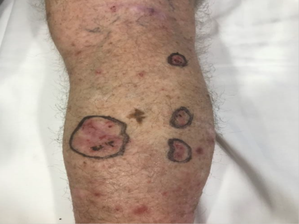
Figure 1B Lesions suspicious for malignancy were examined. Circles identify and outline the tumour extent.

Figure 1D Benign visible skin structures within the plastic sheet area (black arrows) are also traced onto the sheet to assist with localisation.

Figure 1E Finished template.
Blue horizontal arrows show orientating labels – superior, medial, inferior. The blue vertical arrow indicates the measurement scale bar. Red stars above the numbers show the lesion numbering. Lesion numbering helps to link biopsies to the appropriate lesion. The area biopsied should be labelled with the corresponding lesion number. The black rectangle covers the place where patient and body position identification are found.
Plastic sheet template technique for RT field recording and verification at treatment
A patient was referred for consideration of post-operative RT (PORT) following resection of a cutaneous squamous cell carcinoma (cSCC) with high risk features that was susceptible to local recurrence. The patient had undergone a simple excision four weeks earlier and presented with a healing five centimetre (cm) scar under the right breast located between the midclavicular line and the midline of the body. Physical examination did not reveal any evidence of persistent or already macroscopic recurrent disease. The radiation oncologist (RO) drew a dotted line over the surgical scar. A second dotted line was drawn surrounding the scar to form an ellipse around the scar. This ellipse identified the field for megavoltage electron (MeV) treatment (Figure 2A). The plastic sheet template was then made. The plastic sheet was laid over the area of interest. The sheet was placed in such a way that it was possible to localise the regional surface anatomy and include it on the sheet. In this case, the sheet overlapped both nipples, and these were traced onto the sheet with a black permanent marker. Other localising marks and the treatment field were traced onto the sheet (Figure 2B) along with the RT field (Figure 2C). Other localising regional surface anatomy was also included in the tracing (Figure 2D). The finished template minus the patient identifying information is shown in Figure 2E. This method allows the template to be photocopied onto an A4 piece of paper which can then be scanned into the patient’s file as a permanent record and reprinted at any time.

Figure 2A Patient being planned for PORT. Anterior trunk of the patient showing recent resection for cSCC, Thin long vertical arrows show the extent of the simple excision. Thick short horizontal arrows indicate the MeV field.
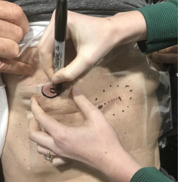
Figure 2B Radiation therapist tracing on the localising regional surface anatomy - in this case both nipples.
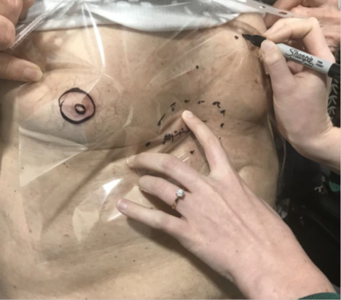
Figure 2D Benign visible skin structures. In this case some benign moles within the plastic sheet area are also traced onto the sheet to assist with localisation.

Figure 2E Finished template. The blue horizontal arrow shows the inferior orientating label. The blue vertical arrow shows the measurement scale bar. Red arrows outline the RT field. The black rectangle covers the place where patient and body position identification are found. Note the localising regional surface anatomy marks of nipples and moles.
As this case was to be treated with megavoltage electrons (MeV) the patient underwent a planning computerised tomography (CT) scan. Wires were placed on the skin marks made by the RO so that the position of the marks could be captured on the CT. The wires were contoured by the planning staff on the planning CT scan using the treatment planning system. They were contoured in such a way that the contours projected out of the patient’s body contour so that they could be seen on a three-dimensional (3D) render of the CT scan (Figure 2F). This is reminiscent of the RT field as drawn on the body in Figure 2A. These steps assist the RO in computer contouring important structures such as the clinical target volume (CTV)7 planning target volume (PTV) and any avoidance structures (AS) (Figure 2G). A tight margin of expansion from CTV to the PTV is possible when there is high confidence in the reproducibility of the treatment field, as enabled by the template. These guide dosimetry planning (Figure 2H).

Figure 2F The wires are contoured in such a way that the contours project out of the patient’s body contour so that they can be seen on a 3D render of the CT scan. The similarity of this to the plastic template is reassuring.

Figure 2G Shows the contours completed. The white coloured wires are surrounded by a pink 5mm expansion indicated by short wide arrows. These large contours enable the wires to be seen as a 3D structure on the patient surface render as in Figure 2F. The green volume containing stars is the CTV. Note the wire overlaid by the double ended arrow which indicates the scar. It is important that the depth of the CTV at this level encompasses the depth of the surgical field obtained from the deep margin information on the histopathology report. The surrounding blue structure indicated by long thin arrows is a 3-millimetre (mm) expansion to the PTV. Note the continuation of the PTV into the bolus to achieve the dose on skin. The turquoise structure containing a cross in the lower photo is an avoidance structure to help with limiting dose to depth.
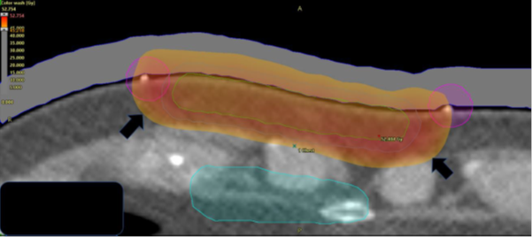
Figure 2H The resulting dosimetry on colour dose wash on an RT planning system. The prescription was 45 Gray (Gy), and the dose cloud at this dose is marked by short wide black arrows. Nine MeV was used with 1cm of bolus to provide a homogeneous dose to the surgical cavity and scar without minimal exit into the dose sensitive mediastinum.
Use of the template to verify the treatment field
When the patient came for treatment, he was set up in the same treatment position used at planning. The template was positioned on his body and the normal anatomy localisation marks on the template were lined up with the normal anatomy as marked during planning (Figure 2I). The treatment field was then drawn on the patient by marking the skin underneath the marks that were made at planning to delineate the treatment field. Some radiation centres use a more rigid plastic sheet that can have holes punched into it to enable a marker pen to make dots directly onto the skin via the holes without having to lift the template (Figure 2J). At the end of this process, the marks on the template accurately align with the marks on the skin (Figures 2K&2L). The linear accelerator light field then overlays the treatment field as it has been drawn on the skin from the template (Figure 2M). Reassuringly, towards the end of the fractionated course of RT, the area of acute skin reaction exactly matches the treatment field drawn on the template (Figure 2N).

Figure 2I At treatment.
The template is placed upon the patient’s body and the normal anatomy localisation marks on the template are lined up with the normal anatomy marked at planning.
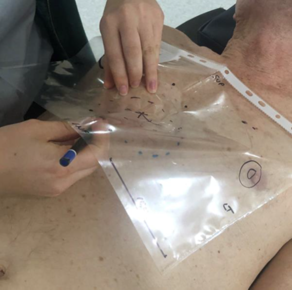
Figure 2J The treatment field is then drawn on the patient by marking the skin underneath the marks that were obtained at planning to delineate the treatment field.
Use of plastic sheet template in superficial radiotherapy
The patient in Figure 3A had a cSCC of the left temple treated definitively with superficial radiotherapy (SXRT) using a Xstrahl 300™ machine (Figure 3). The template was made as previously described. SXRT does not require computer planning so there was no need for a CT scan or contouring. SXRT planning consists of marking out the lesion and adding a margin to the edge of the field (Figure 3A).
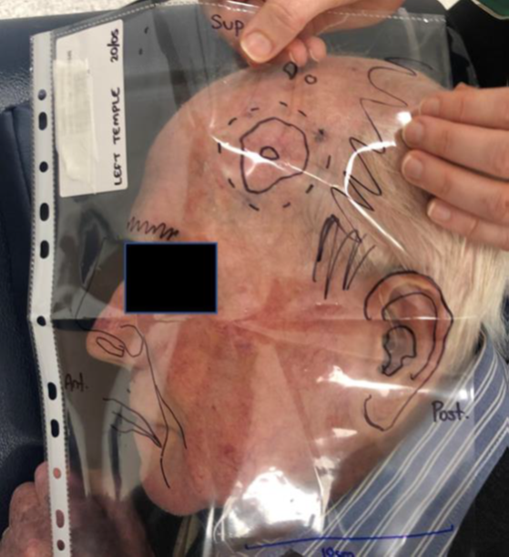
Figure 3A Man with a cSCC of the left temple is planned for definitive SXRT. The template is laid over the target area and orientated.
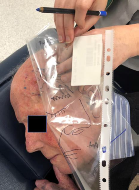
Figure 3B As also described in Figure 2J, the treatment field is drawn on the patient by marking the skin underneath the marks that were used at planning to delineate the treatment field.

Figure 3D A customised treatment cut-out is placed in position over the field marks. The cut-out further collimates the beam at the skin surface avoiding unnecessary RT to the surrounding normal tissues.
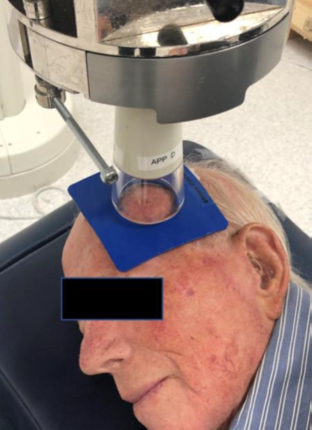
Figure 3E The head of the Xstrahl machine is placed on the cut-out just prior to treatment. The lead glass at the end of the applicator means that the treatment area can be directly visualised during set up, ensuring proper field placement. The advantage of SXRT is that the head of the machine can be used to keep the cut-out and patient anatomy in position, meaning that customised immobilisation devices such as masks are not needed. The applicator that is contact with head means that a mask is not routinely made. This decreases the time the patient is on the treatment bed associated costs and increases patient comfort.
Figure 3Use of a plastic sheet template in superficial radiotherapy
Storage of the template and use in recurrence
After treatment completion, the template can be stored for follow up use. Some departments file them in a ring binder, but this can be messy, and marks can be smudged. Paperless departments can photocopy the transparent template and then scan the A4 paper copy into the patient’s electronic medical record, providing a permanent record of the treated area. This knowledge can help determine whether any recurrence is in-field, at field edge or out of field, thereby assisting the multidisciplinary clinic to choose the most appropriate salvage modality.
Case 4 is an elderly lady who had a biopsy-positive cSCC on the lateral aspect of her right lower leg. She underwent planning with a plastic template and received 15 Gy of a planned 45 Gy, but she then became unwell due to other issues and required months of hospitalisation. She recovered and came back to complete her treatment. The previous template was printed and the size of the lesion at planning was compared with her current lesion. The template enabled the team to identify significant growth since the end of the previous treatment, and on that basis, she was deemed to possibly have a radioresistant cancer and was referred for alternative therapy (Figure 4). The advantage of an electronically stored template is that it can be retrieved at a networked site if the patient needs to be treated elsewhere. This happens, for example, when there is only one centre in the network with specialised equipment, such as a SXRT machine. The template can be downloaded and used to assess previous fields without having to bother the centre where the first treatment was given. This also saves valuable time as opposed to waiting for the physical original template to be sent over from the previous centre.

Figure 4 An elderly lady with cSCC on the lateral aspect of her right lower leg planned with a template received 15 Gy followed by a long break. On her return, the planning template that had been electronically stored was printed out and the size of the lesion at planning (blue arrow) was compared with the current size (red arrow). Overlay was possible as the localisation marks of the template correspond to benign normal skin structures on the leg (both template and skin structures are marked with blue star). The measurement scale bar can show if there has been any magnification of the template during storage and photocopying and this can be accounted for. The template showed there had been significant growth. Alternative therapy was recommended.
Localising in vivo dosimetry
Another use of the template at the planning stage that has not been discussed in the case studies is the ability to record exactly where the RO wants to have in vivo dosimetry performed by the physics staff. An X can be placed on the template and these positions numbered, analogous to the use of numbering for biopsy. The in vivo dosimetry results can then be recorded with the same numbering system so that the exact position of where the dose was recorded can be known with certainty.
This case series is the first report on the use of the humble A4 plastic sheet protector as a multipurpose radiotherapy template, despite it being widely used in our country to verify skin treatment metrics. Treatment verification is essential in radiation therapy. The usual verification scan prior to treatment is excellent for internal cancers but not for skin. A literature search for ‘template’ in skin cancer reveals that the word template has a multitude of meanings. Cumsky et al.8 report on templates for tele-dermatology but refer to the effects of standardised templates and standardised cutaneous oncology learning modules on tele-dermatology referrals, examining how standardised consultations between physicians and patients result in significantly greater efficiencies. At the time of writing, the closest article we were able to find, using templates in a similar manner, is in the selection of brachytherapy applicators for skin cancers.9 The plastic sheet can be used to help verify the position of skin lesions for biopsy, for radiotherapy planning and treatment with either megavoltage or superficial radiotherapy, for recognising any future recurrence by reviewing a stored copy, and for helping to localise exactly where in vivo dosimetry needs to be measured. Anecdotally, some treatment centres use a hard plastic sheet through which holes can be punched to enable the shape made at planning to be redrawn onto the skin. We find the increased flexibility of the A4 plastic sheet protector preferable. The protector is also easier to store in an A4 ring binder during the duration of treatment because of the manufacturer’s holes along its side, although electronic storage is preferred.
The humble A4 plastic protector sheet is easy to construct and use to delineate areas of skin for biopsy and treatment with radiotherapy. It is reproducible, economical and storable. It can also be used to identify whether a recurrence is in-field or not, and helps in clearly defining the point where in vivo dosimetry should be measured.
The authors wish to acknowledge the staff and skin patients attending the Genesis Care Mater Sydney Radiotherapy Department. We also wish to thank Aileen Eiszele of A&L Medical Communications for writing assistance and manuscript preparation.
None.
The authors have no conflicts of interest to declare.

©2020 Alcevski, et al. This is an open access article distributed under the terms of the, which permits unrestricted use, distribution, and build upon your work non-commercially.