International Journal of
eISSN: 2574-8084


Educational Review Volume 9 Issue 2
1Icon Cancer Centre, Revesby, New South Wales 2122, Australia
2Icon Cancer Centre, Gosford, New South Wales 2250, Australia
3Strategic Investment and Clinical Care, Icon Cancer Centre, Queensland 4101, Australia
Correspondence: Gerald B. Fogarty, Icon Cancer Centre, Revesby, New South Wales 2122, Australia, Tel +61 (2) 87222800, Fax +61 (2) 87222801
Received: June 27, 2022 | Published: July 25, 2022
Citation: Fogarty GB, Bell N, Parker T, et al. A scientific approach to skin radiotherapy nursing Article 3 - The skin RT prescription and plan especially in relation to volume and dose. Int J Radiol Radiat Ther. 2022;9(2):69-79 DOI: 10.15406/ijrrt.2022.09.00326
Nurses play an important role in the RT of skin and its diseases. This is the third of four articles that attempts to provide a scientific basis for nurses to better understand skin RT patients, skin and its diseases, and acute RT skin reactions and how to care for them to achieve the best outcomes from RT treatments.
The first paper outlined the role of the nurse as an integral part of the radiation oncology team and how to conduct an effective patient assessment to ensure the patient’s optimal journey to treatment completion. The second article described the anatomy, physiology, pathology and radiobiology of skin and its diseases. This third article describes the skin RT prescription and plan, especially in relation to volume and dose. The fourth paper will show how the nurse, by applying the knowledge from the previous articles, can predict, explain and care for any side effects that may arise.
This knowledge is important for establishing patient expectations, preparing the patient for side effects, and giving scientifically based reasons for complying with care protocols. Hopefully, these articles will help support the nurse to deliver best care to skin RT patients. More prospective research is needed to elucidate the many remaining facets of nursing care for skin RT patients.
Keywords: radiotherapy, radiobiology, radiation effects, radiotherapy planning, computer-assisted, intensity-modulated, skin, skin cancer, nursing, review
The first article1 in this series of four focused on the role of the nurse within the radiation oncology department and the initial patient assessment. The second article2 described the anatomy, physiology, pathology and radiobiology of skin and its diseases. This third article describes the skin RT prescription and plan, especially in relation to volume and dose. This knowledge is important for establishing patient expectations, preparing the patient for side effects, and giving scientifically based reasons for complying with care protocols. The RT modalities discussed herein are those commonly used in clinical RT in Australia to treat skin. These are mainly kilovoltage photons otherwise known as superficial RT (SXRT), megavoltage electrons (MeV) and megavoltage photons (MV). A glossary of terms as they appear in the text is outlined in Table 1.
|
Word |
Meaning |
|
Prescription |
The medical order from a doctor for radiation treatment which details intent, patient treatment set up details, volume to be treated, modality, technique, total dose, fractionation pattern, organs at risk and maximum doses allowed to these organs during treatment. |
|
Plan |
Application of the prescription to the patient anatomy being treated. The plan includes estimates of the radiation dose the volumes being treated and the organs at risk (OAR) will receive. The radiation oncologist (RO) needs to accept the plan before the plan can be implemented; that is, for treatment to proceed. With megavoltage treatment, the resultant dosimetry in tissue can be displayed on a planning computed tomography (CT) scan with a planning software system. |
|
Intent |
Describes whether the treatment is for palliative or radical purposes. |
|
Palliative |
A treatment intent that aims for symptom relief or prevention to increase quality but not necessarily quantity of life. |
|
Radical |
A treatment intent for when the total eradication of the tumour in the treatment volume is the reason for RT. |
|
Definitive |
Definitive treatment is the main treatment of a lesion |
|
Adjuvant RT |
Radical RT that accompanies the main treatment (e.g. surgery) which is aimed at increasing the efficacy of the main treatment. |
|
Salvage RT |
Radical RT given when the tumour has a gross recurrence following a previous treatment. |
|
Bolus |
Tissue equivalent material mainly used to ensure full dose to the skin surface. |
|
Gross tumour volume (GTV) |
The extent of the tumour mass seen clinically; that is, at physical examination and on imaging. |
|
Clinical target volume (CTV) |
The tissue volume that contains the GTV and any subclinical microscopic malignant cells. |
|
Planning target volume (PTV) |
A tissue volume that includes the CTV plus a margin, mainly to allow for daily variation in patient setup. The RT prescription usually indicates a minimum dose required to the PTV. |
|
Dosimetry |
The quantitative measurement of RT dose throughout the treated volumes. This is often displayed on a planning CT for megavoltage treatments where a dose volume histogram can be generated. |
|
Conformity index |
A measure of how the volume that is treated to therapeutic dose compares, or conforms, to the volume that needs treatment, that is, the PTV. |
|
Homogeneity index |
A measure of whether the dose is the same throughout the PTV. |
|
Brachytherapy (BT) |
Where live radioactive isotope sources are laid on or implanted into the tumour. |
|
Penumbra |
A zone at the edge of the full beam where the dose decreases from the full dose to zero dose. |
|
Half value layer (HVL) |
The HVL is the width of a material required to reduce the x-ray intensity to half its original value. Usually only used clinically in SXRT. |
|
PORT |
Postoperative RT |
|
RO |
Radiation oncologist |
|
RT |
Radiotherapy |
|
Geographic miss |
Describes when the wrong volume has been treated. |
Table 1 Glossary and explanation of terms used in this paper
The radiation prescription
The radiation oncologist (RO) writes a radiation prescription that is based on the patient’s clinical need. The script will detail the intent of treatment, the patient’s set up details, the volume to be treated, volumes to be avoided (as required), treatment modality and technique, total dose, and the RT dose fractionation pattern.
Intent of RT – radical or palliative: The intent of treatment signifies whether treatment is palliative or radical. Palliation is for symptom relief or prevention to increase quality, not necessarily quantity, of life. Total sterilisation of all tumour cells in the target volume is not the aim of palliative therapy. The total doses of radiation in a palliative script are less than in a script with radical intent. The fraction size, or the amount of dose delivered per treatment, is usually larger in this setting. These two factors mean that less visits to the department are needed, and this aligns well with the palliative aim of enhanced quality of life in what could be the patient’s last months. Larger fraction sizes are prescribed as the patient is not expected to live long enough to exhibit late effects. Late effects are defined as starting six months post RT.3 Late effects are caused by a large fraction size in normal tissue as discussed in Article 2.2
Radical treatment is when total eradication of the tumour in the treatment volume is the reason for RT. Radical treatment can be given as definitive treatment. This is when RT is the only or main treatment given. RT can also be given as adjuvant treatment, which is when RT accompanies the main treatment – in skin this usually means alongside surgery. A typical example is postoperative RT (PORT) following an excision that has left a positive margin, as detailed in the histopathology report, and where further surgery is declined or not possible. RT is then offered to eradicate the microscopic residual cancer. The RT dose for adjuvant treatment is usually slightly less than that needed for definitive RT given for macroscopic disease. This may be due to macroscopic disease having a greater chance of hypoxic areas, with hypoxia being a known cause of cancer radiation resistance.4 Radical RT can also be given in the salvage scenario when there is a gross recurrence of tumour following a previous treatment and when other treatment, such as more surgery, is declined or not possible.
Treatment volumes
Fundamental concepts that come into play in devising the prescription and the plan are the volumes of tissue that need to be treated, the doses that are needed in those volumes, and the volumes of normal tissues that preferably are to be avoided.
Both volume and dose are important, but perhaps treatment volume is more significant than treatment dose. If the right volume is treated to the wrong dose, then at least some of the right volume has received treatment. However, if the wrong volume has received the right dose there has been what is termed a ‘geographic miss’, which is the mortal sin of RT. In geographic miss, the right volume is untreated and the wrong volume suffers the side effects of RT.
International commission on radiation units and measurements: Radiotherapy volume definitions
The RO is primarily responsible for defining the treatment volumes. There is a convention around the volumes that have been defined in successive publications of the International Commission on Radiation Units and Measurements (ICRU)5,6 These are represented graphically in Figure 1. The gross tumour volume, or GTV, is the extent of the tumour mass as seen clinically; that is, at physical examination and on imaging. The clinical target volume (CTV) is defined as the tissue volume that contains the GTV and subclinical microscopic malignant cells. The latter are not apparent on physical examination or imaging but are known to be there by data and experience, especially from histopathological studies of resected specimens, recurrence patterns and autopsies. Knowledge of how cancer spreads, especially to draining regional lymph nodes, is needed to know the CTV for any given tumour. It has been said that radiation oncology is a CTV speciality (Dr Sam Ngan, personal communication).
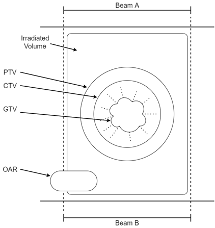
Figure 1 ICRU radiotherapy volume definitions are shown in this diagram. This shows an arrangement of radiotherapy beams called a ‘parallel opposed pair’. Beams A and B are arranged facing each other, that is, at 180 degrees to each other on either side of the body, irradiating a tumour through the body. The gross tumour volume (GTV) is the extent of the tumour mass. The clinical target volume (CTV) contains the GTV and subclinical microscopic malignant cells. The planning target volume (PTV) is the CTV plus a margin to allow for daily variations in patient setup. The irradiated volume is the tissue volume which receives a dose that is considered significant in relation to normal tissue tolerance. Organs at risk (OARs) are organs in or close to the treatment volumes that are at risk of being damaged by RT. The dose needs to be known in these before the plan is accepted by the RO. See text for further explanation.
The planning target volume (PTV) is the CTV plus a margin, mainly to allow for the small daily variations in patient setup that are inevitable in a fractionated course. The RT prescription usually indicates a minimum dose needed to the PTV. The radiation planners will work off the dose prescribed to the PTV to produce an acceptable plan for the RO to sign off.
The margin needed for the PTV will also depend on the quality of the immobilisation. The term “immobilisation” refers to the methods employed by radiation therapists to help keep the patient still during treatment delivery with the aim of reproducing the same position as at planning for each fraction. Excellent immobilisation means the margin for PTV generation can be decreased, meaning less normal tissues are in the high dose volume. A patient may volunteer to the nurse that the immobilisation device is becoming loose as treatment progresses. Looseness in the immobilisation device during treatment can be caused by weight loss or by tumour shrinkage. This can lead to a geographic miss of the PTV and treatment failure. Where such concerns are expressed, the nurse needs to check the patient’s weight against their baseline measurement and report this to the RT treatment staff. This may necessitate a replan.
The PTV is usually made a bit bigger for a patient in pain as there is more chance that they will change position between treatment set up and delivery. An initial nursing assessment of a patient’s pain on a scale of 1-10 at baseline and at regular intervals throughout treatment can help alert thechanges in a patient’s pain needs. Regular review of pain and pain management medications and strategies will ensure that any required interventions are timely, appropriate, and adequate throughout treatment. This can help to avoid a replan during treatment.
The irradiated volume is the tissue volume which receives a dose that is considered significant in relation to normal tissue tolerance. The integral volume is the total volume of tissue getting any radiation. Keeping the irradiated volume to a minimum with good planning means that less normal tissues are in the high dose volume, and therefore there are fewer side effects in normal tissues. Organs at risk (OARs) are organs in, or close to, treatment volumes that are at risk of being damaged by RT. Dose limits are placed on these in the radiation prescription (Figure 1).
Homogeneity and conformity of RT to the treatment volume
The conformity index is a measure of how the volume that is treated to therapeutic dose compares or conforms to the volume that needs treatment, that is, the PTV. The closer these two volumes are, the higher the conformity index of the treatment and the less normal tissues receiving a high dose are in the treated volume, resulting in less side effects. The homogeneity index is a measure of whether the dose is the same throughout the PTV. The ideal treatment is one that achieves a homogenous dose throughout the volume that needs treatment, with high conformity. This means that there is rapid dose fall off outside that volume, so there is little dose to surrounding normal tissues that may be radiosensitive and prone to side effects.
Put simply, the problem with RT is that RT beams traditionally came in blocks, but bodies come in curves – the square peg and round hole problem. This technique is called three dimensional conformal RT (3DCRT). Technical advances have overcome this. The first evolution was a technique known as intensity modulated radiotherapy (IMRT). This helped reduce dose to normal tissues, that is, with greater conformity. With IMRT, RT is still delivered through fixed beam angles and so takes time. IMRT was therefore initially rationed to cases thought more deserving of better conformity, like paediatric and radical retreatments. The next evolution was volumetric modulated arc therapy (VMAT), where the radiation source moves around the patient, irradiating while it moves. This is like having the radiation source inside a CT ring. VMAT means that even better conformity can now be achieved in an even shorter time. VMAT enables the entrance and exit RT beams to be diluted through more normal tissue, meaning less normal tissue receives a high dose, further improving conformity. Nowadays, most MV EBRT is delivered using VMAT, even in palliative cases.
Advances in computer planning and fusion with diagnostic imaging modalities, such as magnetic resonance imaging (MRI) and positron emission tomography (PET), have also helped to increase conformity and homogeneity. The evolution of external beam radiotherapy (EBRT) from 3DCRT through IMRT to VMAT is detailed in Figure 2A.
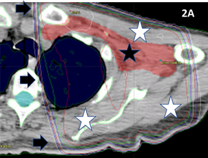
Figure 2A 3DCRT plan of the axilla. The black star indicates the PTV drawn by the RO. A parallel opposed pair has been planned to deliver RT. Black arrows indicate the dosimetry lines that are a spectrum of colours showing the intensity of the RT. These lines are like lines on a map showing altitude, but here they show dose. In this plan, the dose to the PTV is very homogenous. However, the plan is not conformal. The white stars show areas of normal tissues that receive the full dose. Because so much normal tissue will receive a high dose, the treatment needs to be fractionated to avoid the radiation repair capacity of normal cells in the high dose area becoming swamped. This approach of significant fractionation reduces radiation late effects in the normal tissues.
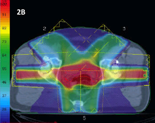
Figure 2B 3DCRT plan of a prostate displayed in dose wash. The spectrum of colours shows the intensity of the RT. The RT planners have applied beams in a 3DCRT planning configuration. The plan gives excellent homogeneity throughout the CTV (the contoured red line), but there is a lot of dose going to surrounding normal tissue, especially the anterior wall of the rectum and hips, meaning that the conformity is poor. This treatment was often given in 35 fractions or more.
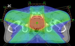
Figure 2C An IMRT plan of a prostate showing better homogeneity and reasonable conformity, especially with improved sparing of the hips. The dose is still being delivered by five beams which takes time.
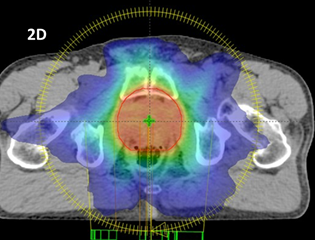
Figure 2D A VMAT plan of a prostate showing equally as good homogeneity if not better than that shown in Figure 2C. There is much better conformity. With the radiation source moving in a complete rotation around the patient, irradiating while moving, the dose is diluted through a lot more normal tissue, allowing better conformity and therefore hypofractionation. This treatment is given in 20 fractions.
Figure 2 Evolution of external beam megavoltage photon techniques that have led to increased conformity and homogeneity and thus enabled hypofractionation.
Nowadays, these technological advances mean that there is less sensitive normal tissue in the pathway of radiation beams. This has allowed a shift, based on excellent prospective research, to hypofractionation. Prescribing a fraction size that is more than the ‘standard fraction’ of 2Gy has become possible without causing debilitating fibrotic late effects in surrounding normal tissues. This means that the total number of fractions needed for cure can be decreased, and less visits to the department are required for the patient.
The evolution of these EBRT modalities may still have room for improvement. What the evolution has done is diluted the unwanted RT through more normal tissue, but usually in a planar fashion. Non co-planar treatment, like that in stereotactic brain radiosurgery treatment (SRS), allows treatment in just one fraction. Excellent patient immobilisation, image fusion, and high conformity mean that in some SRS treatments the GTV equals the PTV. No expansions of the high dose plan into normal tissues are needed.
Modalities of Skin RT
The geographical relationships of the volumes that need to be treated, and those that need to be avoided, will determine what modality of RT will be used. Skin cancer, unlike other cancers, needs beams that provide a significant dose to the skin surface but minimal or no penetration to deeper normal tissues.
Each radiation treatment modality offers a different way of delivering RT. Each modality has advantages and disadvantages for treating skin (Table 2). The two main modalities are (i) brachytherapy (BT), which involves live isotope sources being laid on or implanted into the tumour, and (ii) external beam radiation therapy (EBRT), where RT is beamed into tissue from a distance called the source surface distance (SSD). In Australia, the usual EBRT modalities used for skin are either superficial photons (SXRT), megavoltage photons (MV), or megavoltage electrons (MeV). Figure 3 provides a comparison of how these modalities deposit dose at depth in tissue.
|
Modality |
Beam Advantages |
Beam Disadvantages |
Other Advantages |
Other Disadvantages |
|
SXRT |
Maximum dose is deposited on skin |
Small field size (maximum 8cm diameter) |
Eye contact with staff during RT |
Needs a special machine |
|
|
Rapid fall off in tissue |
No planning system to record dose in tissue |
Less radiation protection requirement |
Staff scheduling can be difficult |
|
|
Tight penumbra |
No portal verification film |
Less immobilization |
|
|
|
Skin collimation |
|
Easy RT set up |
|
|
|
|
|
Sometimes no need for transfer to treatment bed |
|
|
|
|
|
No need for planning CT |
|
|
|
|
|
Cheap treatment and machine cost |
|
|
|
|
|
|
|
|
MV Electrons |
Rapid fall off in tissue |
Wide penumbra |
Uses Linac |
Needs a linac so needs a bunker |
|
|
Planning system to record dose in tissue |
Usually needs bolus to achieve maximum dose on skin |
|
Immobilisation devices needed
|
|
|
Wide fields (up to 20x20 cm) |
No portal verification film |
|
Set up time longer |
|
|
Skin collimation possible |
Best with flat surface to beam |
|
Bed transfer needed to treat |
|
|
|
Cannot treat through the treatment couch |
|
|
|
|
|
|
|
|
|
MV Photons |
Relatively tight penumbra except in tangential VMAT |
Needs bolus to achieve maximum dose on skin |
Uses Linac |
Needs a linac so needs a bunker |
|
|
Planning system to record dose in tissue |
|
|
Immobilisation devices needed
|
|
|
Wide fields (up to 40x40cm) |
|
|
Set up time longer |
|
|
Portal verification film possible |
|
|
Bed transfer needed to treat |
Table 2 Advantages and disadvantages of Skin RT EBRT modalities
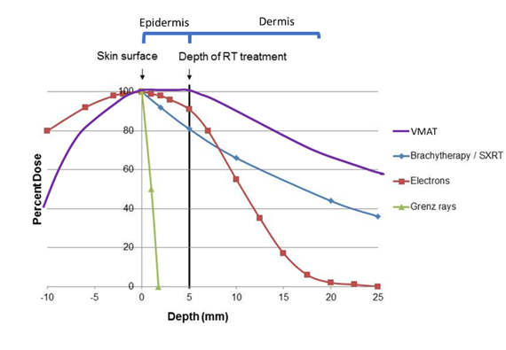
Figure 3 This graph shows the depth doses of different RT modalities through the first few layers of skin. The thin grey vertical line at zero represents the skin surface. The thick black vertical line represents 5mm into tissue, the deepest point that skin appendages penetrate. This area can be classed as the volume that contains the epidermis. Megavoltage modalities (Purple line = volumetric modulated arc therapy [VMAT] and red line = electrons [MeV]) need “bolus” to ensure full dose delivery to the skin surface.
Brachytherapy
The first modality used to treat skin was brachytherapy (BT), which involved placing live isotope sources directly onto the tumour. Radioactivity was discovered in 1896, and BT was used for skin disease within 10 years of this discovery. BT gives a rapid dose fall off - there is little dose left by the time the dose cloud reaches normal tissue under the tumour. BT can be from a sealed source, where the isotope is sealed within a container, or unsealed, where it is not. Sealed sources have more reliable dosimetry and are more safely handled and discarded.
Skin BT has decreased in use for several reasons. There are radiation protection issues with a source that is always ‘on’ and cannot be switched off like EBRT. Making moulds for sealed source BT is a niche radiation therapy speciality and not available in every RT department. Mould making takes time. A small difference in placement of the mould, inevitable between fractions, can lead to a large change in dose delivery due to the very rapid falloff, and this can create uncertainty in the actual dose delivered. An RT modality called electronic brachytherapy exists, but it is really a type of EBRT. BT may be coming back into vogue as an unsealed single application of rhenium-188 paint, but more research is needed to determine if this unfractionated treatment will lead to more late effects, which should be detectable at the two year mark post treatment.
Modalities of EBRT for skin RT
The EBRT modalities differ in a number of ways, including penumbra and penetration. In EBRT, radiation penumbra is one factor which hinders the confinement of the dose to tumour volume. The penumbra is a zone at the edge of the full beam where the dose decreases from the full beam to zero. The penumbra is essentially useless radiation - it is too little to kill cancer and yet may be enough to cause side effects in surrounding normal tissue. The penumbra causes unnecessary irradiation of the surrounding normal tissues in the penumbral region, decreasing the conformity index. (Figure 4A). Penumbral issues in skin, like keratoacanthoma7 and hair pigment change,8 have been reported.
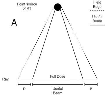
Figure 4A A point source of radiation shining on a field. In the middle of the beam, the full dose is being delivered. At the edges of the beam is the penumbra (P). This is where dose decreases from full to zero dose. The size of the penumbra depends on many factors; the most important is the size of the source and the modality.
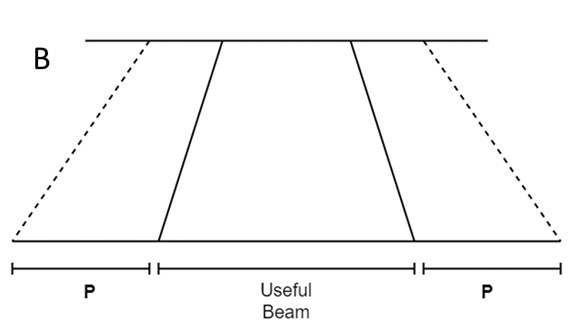
Figure 4B Close up of an electron penumbra (P). This is wide compared with other modalities like SXRT in C.
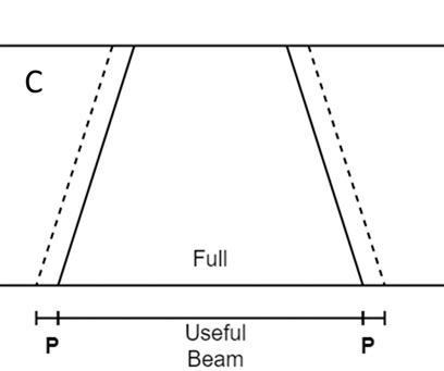
Figure 4C Close up of an SXRT penumbra (P). This is thin compared with other modalities like electrons in B.
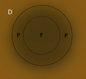
Figure 4D A six MeV electron field displayed on GAFchromic™ paper. The inner circle is the full beam (F), the outer circle is the field. In between the drawn circles is the penumbra (P). Note the wide diffuse penumbra as demonstrated schematically in Figure 4B.
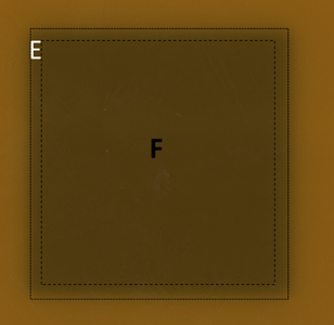
Figure 4E A 6MV photon field displayed on GAFchromic™ paper. The inner square is the full beam (F), the outer square is the field. The penumbra is sharper than electrons but not as sharp on skin as SXRT as shown in Figure 4F.
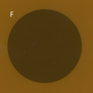
Figure 4F An SXRT field displayed on GAFchromic™ paper. The tight penumbra of the SXRT beam is difficult to see. This property makes the SXRT beam excellent for irradiating close to delicate structures such as eyes.
Figure 4 The penumbras of different RT modalities used in skin RT. Figures 4A-C are schematic. Figures 4D-F are the result of a beam of a certain modality being shone onto a piece of GAFchromic™ paper, a common quality assurance measure by the physics team.
Superficial RT (SXRT)
After BT, the next modality developed to treat skin conditions was via a machine that produced kilovoltage X- rays in around 1915. Today, these machines are known as superficial RT (SXRT) machines. Modalities like SXRT include Grenz rays. Grenz rays have very little penetration into skin and are rarely used these days. There was a significant failure with Grenz in treating lentigo maligna because of the lack of penetration depth.9,10 Another similar modality is electronic brachytherapy. This is really a SXRT machine with a very short SSD, meaning that it can only treat small thin lesions.
ROs usually prescribe to the PTV. In SXRT, PTV is often equated with field size that is drawn on the skin. SXRT has a sharp penumbra and is therefore excellent for irradiating close to delicate structures, such as the eyes. For a small thin lesion on the face, especially if situated close to an organ at risk, e.g. an eyelid, SXRT is ideal (Figure 4A). Two key advantages of SXRT beams include deposition of the maximum dose on the skin and a comparatively rapid exponential fall off in tissue, depending on the generating energy and SSD, with dosimetry similar to BT (Figure 5).

Figure 5 SXRT depth dose in skin. There is 100% dose at the skin surface and a comparatively rapid exponential fall off in tissue.
Shields are made these days from lead equivalent material, not from lead itself, making SXRT safer. Enveloping the shield in (Figure 6A)protective glad wrap prior to RT is no longer required, which saves time. Treatment staff also know to anchor the shield by taping it to skin outside the treatment field. No adhesive tape should be used in the treatment field to anchor dressings etc as it can aggravate acute effects. Figure 7 illustrates how a purpose-built shield is secured by tape that is attached to skin well outside the treatment field. The daily application of the shield may cause trauma, aggravating any mucositis that will occur on the inside of the lower lip as the course of RT progresses. Weekly inspection of the oral cavity for ulcers and other evidence of trauma, as per the case in Figure 7, together with early intervention, may aid in timely RT course completion. Shielding on skin can be used in SXRT to protect normal structures. In Figure 7, the upper half of the shield is protecting the upper lip.
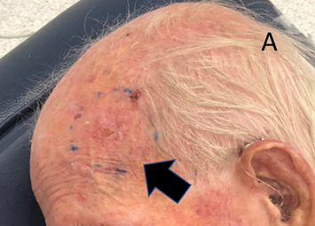
Figure 6A The RO has drawn the SXRT treatment field onto the skin. It is a circular shape measuring 4.5cm in diameter.
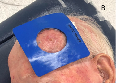
Figure 6B The 5cm SXRT applicator is too big, so a 4.5cm diameter shape called a cut-out is made to protect the normal skin that does not need RT.
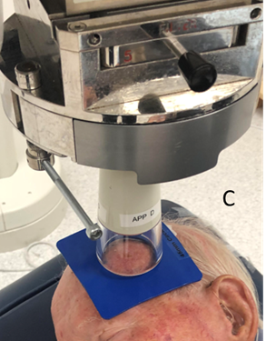
Figure 6C The SXRT applicator is laid on the material and only the skin within the 4.5cm area that needs RT is irradiated. Using pi = 3.14, a 5cm diameter applicator treats 78.5 cm2, while with a 4.5cm cut-out, 63.6 cm2 is treated. Therefore, over 20% less normal tissue is being treated using the cut-out.
Figure 6 Use of lead-equivalent material to decrease the area of normal skin getting RT.
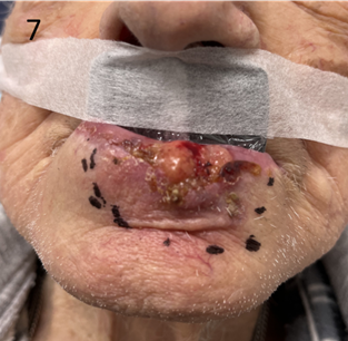
Figure 7 Use of an “in-out” shield for definitive SXRT treatment of a lower lip cancer. The lower part of the lead equivalent material is put into the lower buccal sulcus behind or inside the lower lip, between the lip and teeth. This will protect the teeth and gums from unnecessary RT that will penetrate through the lip as the lip cancer is treated. The upper part of the shield is outside the upper lip, which does not require RT. The upper lip needs to be free of RT reaction so that this man can eat, thereby nourishing the normal cells so that they can repair between the fractions. It is important to ensure that the tape is secured onto skin well outside the treatment field This shield was made with that in mind.
SXRT has several other advantages. As it is a kilovoltage energy, the requirements for protection are less, meaning that SXRT doesn’t need a bunker lined with thick concrete as is the case with a linear accelerator that produces megavoltage RT. Eye contact with staff can be maintained through a lead glass window between the treatment console and the treatment room, which can be important for cognitively impaired patients who may find it challenging to stay still during RT. The small size of the SXRT treatment head means that it can be moved easily, enabling the patient to be treated in their wheelchair or bed without having to be transferred onto a machine-specific treatment couch (Figure 8). There is less need for immobilisation devices like masks which can upset the claustrophobic. Overall, SXRT treatments are also cheaper than linear accelerator (linac) based treatments.
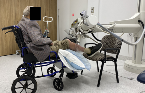
Figure 8 This person is being treated with SXRT for a leg lesion. SXRT has the advantage of a small mobile treatment head enabling treatment to be delivered in a wheelchair or bed rather than requiring patient transfer onto a treatment couch.
SXRT beam disadvantages are as follows. Given that the radiation source is close to the body compared to megavoltage treatments, homogeneity cannot be guaranteed over large areas. This limits the treatment field to around an 8cm diameter maximum, depending on the SSD of the machine. As there is no SXRT computer planning system, there is no need for a CT planning scan, but this means that there is also no CT dosimetry record of where the dose has fallen at depth in tissue. There is no penetration of the beam through the body, so no portal verification film can be taken. Portal films can be taken when megavoltage photons are used so the actual treatment volume can be verified.
Megavoltage beams
MV beams were made possible in the 1970s with the invention of the linac. A key advantage with linac treatment is that the SSD is longer, so the beam front is more parallel when it arrives at skin level. This enables treatment to be delivered to area of skin as great as 40 x 40cm. Usually, MV beam planning requires a planning CT scan to plan where the dose will actually be deposited and to help maximise homogeneity through the treatment volume.
There are also disadvantages. Safety precautions due to a more penetrating beam mean that staff are separated from the patient, often by thick concrete walls in the form of a maze. The patient is left longer in the treatment position, so immobilisation devices are routinely used that can sometimes pose a problem for the claustrophobic. MV beams are ‘skin sparing’. MV beams deposit their maximum dose at depth in tissue. In skin cancer, however, the tumour is in the skin, meaning that skin is the target organ rather than an organ at risk. Tissue equivalent material called bolus must therefore be used on the skin to ensure full dose delivery to the skin surface. This means that the treatment area, once fully set up, is underneath the bolus and cannot be visualised, making geographic miss more likely. There is a need to transfer the patient onto the machine couch, as treatment in the patient’s bed or wheelchair is usually not possible.
Megavoltage electrons
MeV electrons have the advantage of a sudden drop off with depth in tissue making them ideal for skin, unlike MV photons which are more penetrating (Figure 9). Electron energies usually used for skin, like six and nine MeV, require the use of bolus material to achieve the full dose on skin. They also have a wide penumbra, meaning that normal tissues close to the treatment volumes can be irradiated. Skin collimation is possible in select cases.11
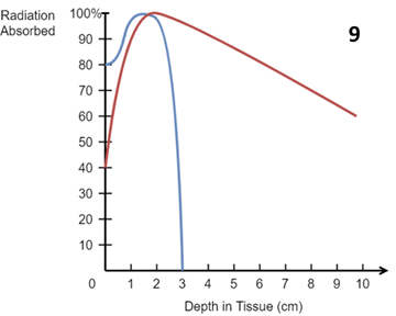
Figure 9 Idealised central axis percentage depth dose (PDD) curves in water for a 10 x 10 cm2 field size and an SSD of 100 cm for a six MeV (electron) beam (blue) and a six MV (photon) beam (red). MeV electrons have a sudden drop off with depth in tissue making them ideal for skin. MV photons are more penetrating and exit dose at depth needs to be considered. Note the surface dose for electrons is around 80%, for MV photons around 40%. Bolus is needed to ensure full dose on skin in these MV beams.
Electron dosimetry is more predictable when the incident beam is perpendicular to a flat surface, and so the RT staff will try to make the surface flat by either changing the anatomy, e.g., turning the head to the side to decrease fall off in contour at the angle of the jaw, or by filling the indentations in the flesh with bolus (Figure 10A). Application and removal of the bolus daily may cause trauma and worsen side effects. Electrons are also not routinely delivered from posteriorly as there are issues with electron scatter going through the treatment couch. Patients needing electron treatment to the back will need to be treated prone, which can be a challenge for some, and may necessitate a change of modality.
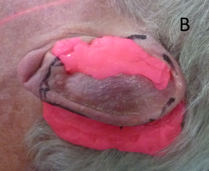
Figure 10B The indentations of the ear are filled. Notice the pink stuff posterior to the ear which will stop penumbral RT falling onto the hair bearing scalp, thereby preventing alopecia. It will also allow ‘dose build up’ to ensure adequate dose to the edge of the pinna.
Figure 10 An ear undergoing electron treatment. In order to present a flat surface to the incident electron beam, the indentations of the pinna are filled up with ‘pink’ bolus on a daily basis prior to each fraction.
Megavoltage (MV) photons
Historically, MV photons have not been the modality of choice in primary skin tumours as the depth dose is too great when treating with the central beam axis perpendicular to the skin surface. However, when the photon beam is used tangentially, extensive skin cancerisation (ESFC) can be treated using a tangential VMAT technique.12,13 For example, areas of ESFC, including convex shapes such as a scalp or forearm with multiple cancerous lesions, can be treated efficiently and effectively as one area in a single course of treatment. This has only been possible since the introduction of VMAT. Tangential use of any beam does, however, increase the penumbra with effect outside the target.7,8 MV photons can use portal verification films to record and ensure that the dose has been deposited as planned. MV photon treatment fields can be wide, up to 40 x 40cm, which is ideal for ESFC, but skin collimation is not possible.
The volume to be treated, especially size and depth, will determine which modality is used
The size and depth of the volume to be treated will determine the appropriate RT modality. When size is the main determiner, a small superficial lesion is best treated with SXRT (field diameter less than 8cm), a larger flat superficial lesion (up to 20 x 20cm) with electrons, and a larger superficial lesion or field with MV photons. When depth is important, a lesion deeper than 1cm is beyond SXRT, and electrons should be used. Deeper lesions, e.g., within a nodal basin, are best treated with MV photons. In the case of a nodal basin where the skin does not need to be treated, the full use of skin sparing MV would be the modality of choice. Bolus would not be used in this scenario, meaning less dose delivery to the skin and fewer side effects in normal skin. Some departments do not have all modalities available, especially SXRT, and a compromise may need to be made when selecting another modality, e.g., electrons.
Bolus
A primary skin tumour needs the maximum dose of RT to be deposited on the skin surface. To achieve this when using ‘skin sparing’ megavoltage RT, a tissue equivalent material called bolus needs to be placed on the skin. Bolus is used to overcome the skin-sparing effect of MV beams, thereby increasing the dose to skin. A disadvantage with bolus is that treatment staff cannot visualise the skin being treated in its final set up position as it lies beneath the bolus.
Bolus comes in all shapes and sizes. There are differences in bolus malleability to account for different scenarios. Pink bolus is very malleable. It is made daily and is single use. Jelly bolus comes in sheets of certain thicknesses and can be reused. Three-dimensional printed bolus is more rigid and is custom made from a planning CT and used throughout the course for treatment for an individual patient. Sometimes just wet gauze is used as bolus. What nurses need to know is that application and removal of the bolus takes time in the treatment room, but this time is time well spent, and they can reassure the patient accordingly.
Patients often think that the aim of bolus is to protect the skin whereas the reality is the opposite – bolus ensures that the prescribed dose goes to the skin. Acute effects can be worsened due to the trauma caused by the daily application and removal of bolus. Bolus often needs to be taped in place which means taping it to skin. The adhesive part of the tape must be outside the RT skin field to reduce the likelihood of trauma; however, trauma from bolus use may be unavoidable in some situations. A layer of cling film (Glad® wrap) is often used as a non-stick protective barrier between the skin and bolus and does not create extra bolus. Where the skin has broken down, the nurse may consult with the RO regarding the use of thin silicone foam dressings beneath bolus, which can offer comfort, absorbency and protection with minimal additional bolus effect.
The same bolus material can have other uses. Bolus can also be used to ‘soak up’ dose so that it does not escape, especially down an orifice; for example, dose for a conchal bowl primary leaking down the external auditory meatus. Bolus can be placed in the nasal vestibule to stop dose penetrating through the alar and unnecessarily irradiating the septum. Nasal vestibule bolus can also help to keep a nasal septal shield in place. However, if inserted and removed poorly, this trauma can worsen radiation mucositis. Bolus can also protect normal tissues from stray SXRT radiation by being placed in between the SXRT machine and the normal tissue not needing RT (Figure 11). Bolus can be used to ‘build up’ dose to ensure dose to the entire field (Figure 12). Bolus can be also used to present a flat surface to an electron beam which decreases uncertainty in surface dosimetry from an uneven surface (Figure 10A).
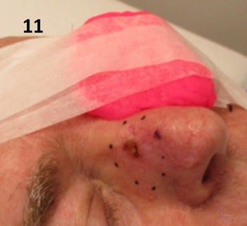
Figure 11 Pink bolus is used to ensure that dose does not stray onto the contralateral cheek and eye when treating a lesion that is on the upper nasal alar with SXRT. Note the bolus is being held in place with tape anchored well outside the treatment field.
Understanding acute RT skin side effects from the perspective of volume
Radical doses of RT will produce side effects in normal skin and other tissues within the high dose treatment volume. The nurse will know the volume from the prescription and treatment plan.
For SXRT, the volume will equal the size of the area of skin being treated by the penetration depth of the beam. Photos taken by the radiation therapist at planning will show the area. Figures 11 and 12 show the area of SXRT fields drawn on noses. The depth will be known by the quality or strength or penetrating power of the beam. When using SXRT, depths are traditionally measured by the half value layer (HVL). The HVL is the width of a material required to reduce the X-ray strength to half its original value. The attenuation of the beam in tissue is described by the percentage depth dose curve. This is best shown graphically (Figure 5). The prescription informs the nurse of the volume being treated, to what total dose it is to be treated, the dose per fraction, and the duration of RT. The photos allow the nurse to know the anatomy and direction of the SXRT beam. Using this information, it is easy to predict the acute RT effects and their duration on the in-field tissues and surrounding areas.
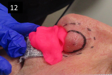
Figure 12 Pink bolus is used to ensure dose build up when treating a lesion that is on the margin of the nasal alar with SXRT. If there was no bolus, the very edge of the ala may not receive sufficient dose for tumour cure. Note that the bolus is resting on a lead-equivalent shield wrapped in plastic foil that is protecting the upper lip from RT that may penetrate through the pink bolus material.
With MV treatment, the treatment volumes and OARs are usually defined by the RO who contours them on the planning computer tomography (CT) scan. The planning radiation therapist then computes the dosimetry according to the prescription. Electrons rapidly fall off with depth, so side effects in deeper tissues are rare. Photons can penetrate, and the exit beam in deeper tissues beyond the target must be considered. The resultant plan can be displayed graphically in the planning system, as show in the Figure 2A prostate plans. As the volumes and doses are known, a dose-volume histogram can be constructed (Figure 13). Dose parameters to volumes can be assessed on these. The prescription will detail the maximum and minimum doses acceptable in these volumes.
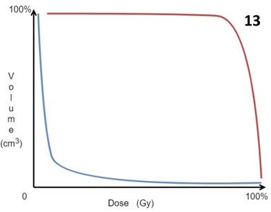
Figure 13 Idealised dose-volume histogram (DVH). This is constructed by the computer during computer planning. The ideal situation is to have the volumes requiring treatment, that is the GTV, CTV and PTV, to have maximum dose to the maximum volume, as depicted by the red line. Conversely it is ideal that the OARs have minimum dose to the minimum amount of the volume as depicted by the blue line. The DVH is produced by the planners and is essential for plan acceptance by the RO.
The aim of planning is to achieve a homogenous dose to the target volume and to spare the OARs from any dose. This usually means making a compromise as the OARs can often lie close to the treatment volumes. The RO must strike the right balance when accepting and approving a plan whilst keeping the needs of the patient in mind at all times.
The nurse can predict the side effects in deeper tissues by accessing the dosimetry plan from the planning staff. The planning staff can illustrate the dosimetry using dose wash. A rule of thumb is that by putting the lower level of the dose wash on half the prescribed radical dose, it is usually possible to see which OARs may experience acute effects. This helps the nurse to set patient expectations and counsel the patient on how to manage the effects on daily life. This notion will be explored in the fourth and final article in this series.
To summarise, acute RT skin side effects will occur within the volume irradiated to a dose that will cause them. The volume determines the modality used, that is, either BT or EBRT. If the latter, then either SXRT, MV electrons or photons can be used (in current Australian practice). The ideal treatment is one which has a homogenous dose throughout the volume that needs treatment, with a high conformity. The available different treatment modalities have advantages and disadvantages when it comes to achieving this. Imperfections like skin sparing and a wide penumbra can be mitigated by the skilful use of patient positioning, immobilisation devices, shielding, and the use of bolus, depending on the scenario.
Dose and fractionation pattern
To understand RT dose, it is necessary to understand the concept of biologically effective dose (BED).14 BED allows the dose with a certain fractionation pattern in one scenario to be equated to another with a different pattern, using 2 Gy per fraction as a standard.
In skin, the following radical dose fractionation patterns are equivalent for tumour control (Table 3):
|
Total Dose (Gy) |
No of fractions |
Dose /fraction |
|
60 |
30 |
2 |
|
54 |
27 |
2 |
|
50 |
25 |
2 |
|
50 |
20 |
2.5 |
|
45 |
15 |
3 |
|
42 |
12 |
3.5 |
|
40 |
10 |
4 |
Table 3 Common equivalent radical dose fractionation patterns in skin
The choice of one fractionation pattern over another depends on many factors, especially when treating skin. The higher the dose per fraction, the less visits to the RT department but the worse the late term cosmetic effects, as described in Article 2 of this series.
Often the choice of fractionation pattern is patient dependent. RT patients are frequently inoperable because of comorbidity and immobility. Often, they rely on others for transport and may not be so fussed with more late fibrosis due to a higher dose per fraction so long as it means less visits. An active person in their 60’s with a BCC on the tip of nose, for example, who wants to avoid the tissue loss of surgery for cosmetic reasons and the risk of long-term side effects may be treated with 60 Gy in 30 fractions. This compares with an older person, who does not have the same concern for cosmesis, who may prefer 45Gy in 15 fractions to avoid having to make twice as many trips. It is therefore difficult to create care pathways for skin treatments as one pattern does not fit all. More research is needed in this area.
Acute side effects arise in a predictable manner, as discussed in Article 2.2 Acute side effects peak at four weeks for those receiving a radical dose with daily (5 days per week) treatment. For treatment of four weeks and over, with the skin getting full dose, the side effects will peak at the end of RT and remain for 10 -14 days following RT.15 For those getting a radical dose in less time, the side effects will still peak at four weeks. This is seen in the case study detailed in Article 22 in this series where the patient received 45Gy in 15 fractions over 3 weeks. The peak side effect was experienced 4-5 weeks after RT had begun.
Acute side effects worsen with increased or more rapid dose per day. They are further enhanced when RT is given with cytotoxic chemotherapy due to the multiple insults to basal cell DNA. Acute side effects may also be aggravated by steroid use as steroids may impede the overnight repair process in normal in-field cells. The use of steroid cream for skin acute side effects needs therefore to be supervised. Poor nutrition also gives rise to enhanced acute side effects as normal cells cannot repair between fractions when nutrition is lacking. For this reason, a weekly weight check is essential even in skin patients, especially those identified as being at risk of malnutrition at the baseline screening assessment.
In vivo dosimetry
Sometimes acute effects in skin can seem out of the ordinary. Skin lends itself to in vivo dosimetry (IVD). IVD is the application of devices directly onto the skin that can measure dose delivery. IVD devices all come with limitations, e.g., different sizes, sensitivities, and the time it takes to provide an answer. The different IVD devices and their advantages and disadvantages are the domain of physicists and beyond the scope of this paper, but there is nothing wrong with a nurse suggesting dose verification if there is a question about over or underdosing.
Use of altered fractionation schedules in the RT of skin
Fortunately, sun-induced non-melanoma skin malignancies seem to be radio responsive.16 By serendipity, there have been successful attempts to reduce acute effects in normal skin with different techniques involving altered fractionation schedules.
The adaptive split course (ASCRT)17,18 is a high dose palliative regime for the frail elderly with inoperable lesions. It involves planning and treatment with half the prescription in a hypofractionated manner to the original tumour (phase I), then a break of six to eight weeks, then a replan and the rest of the treatment (phase II). One study18 examined 22 evaluable lesions. Eight weeks after phase I of treatment,11 of 22 lesions (50%) had a complete response and phase II was not needed. For those requiring phase II, there was a shrinkage of the PTV by 70% after phase I. Six more lesions achieved a complete response two months after completion of both phases, for a total complete response rate of 17 of 20 (85%) following RT, with two lost to follow up. The peak acute reaction was dry desquamation. The median follow-up time was 12 months.
VMAT for extensive skin field cancerisation (ESFC)13 shows a response rate of 98% at 12 months for patients who complete the prescription. The technique was tweaked to include a break of two weeks between fraction 10 and 11 to reduce acute toxicity.19 This appears to have worked without an increase in in-field failure. Clear communication is needed with these innovations as a change in technique could mean a change in the level and type of acute effects expected.
Understanding acute RT skin side effects from the dose perspective
To summarise, all other effects being equal, RT skin side effects arise in a predictable manner. The BED allows the clinician to trade off the total dose and dose per fraction, and therefore the number of treatments, for late effects. The choice of fractionation pattern is often patient dependent. Acute side effects are worse with more rapid dose, when given with cytotoxic chemotherapy or steroids, and when nutrition is poor. Sun-induced non-melanoma skin malignancies seem to be radio responsive and this has led by serendipity to successful altered fractionation patterns that have decreased acute RT skin side effects.
This third article set out to describe the skin RT prescription and plan, especially in relation to volume and dose, to help the nurse predict and explain to patients the acute side effects that may arise from treatment.
From a volume perspective, acute RT skin side effects will occur within the volume irradiated to a dose that will cause them. The volume to be treated determines the modality used, that is, either BT or EBRT. If the latter, either SXRT, MV electrons or photons can be employed. The ideal treatment is to have a homogenous dose throughout the volume that needs treatment, with a high conformity. Modalities have advantages and disadvantages in achieving this. Imperfections like skin sparing and a wide penumbra can be mitigated by the skilful use of patient positioning, immobilisation devices, shielding, and the use of bolus in different scenarios.
From a dose perspective, RT skin side effects arise in a predictable manner. The BED allows one to trade total dose, dose per fraction, and therefore the number of treatments, off for late effects. The choice of fractionation pattern is often patient dependent. Acute side effects are worse with more rapid dose, when given with cytotoxic chemotherapy or steroids, and when nutrition is poor. Sun-induced non-melanoma skin malignancies seem to be radio responsive and this has led by serendipity to successful altered fractionation patterns that have decreased acute RT skin side effects.
The final article in this four-part series will describe how the nurse can predict, explain and care for the side effects using the knowledge acquired from the previous three papers.
The authors would like to acknowledge the ongoing support of Xstrahl for making this publication possible. We also wish to thank Aileen Eiszele of A&L Medical Communications for writing assistance and for overseeing the journal submission process, as well as Jack Fogarty for medical illustrations.
All authors declare that there are no conflicts of interest.

©2022 Fogarty, et al. This is an open access article distributed under the terms of the, which permits unrestricted use, distribution, and build upon your work non-commercially.