International Journal of
eISSN: 2576-4454


Mini Review Volume 2 Issue 4
Emperor Alexander I State Transport University, St. Petersburg, Russia
Correspondence: Perminov NA, Emperor Alexander I State Transport University, St. Petersburg, Russia
Received: August 06, 2018 | Published: August 16, 2018
Citation: Perminov NA. Application of electroosmosis and monitoring for the management of geotechnical processes in underground construction. Int J Hydro. 2018;2(4):498-502. DOI: 10.15406/ijh.2018.02.00117
A new concept for the selection of rational construction and engineering parameters for the building of large deep-set edifices is set out for an environment where the requirements on preservation of historical sites and rational usage of land in big cities and growing more taxing. Based on the proposed geotechnical model, and the assessment of the results of quantitative modelling, research and experiments, a number of techniques have been developed intended to optimise the technological modes of construction under adverse urban conditions involving hard-to-handel soils and constrained urban ambience.
Today the problem of working out the complex measures providing high quality building turns out to be very actual. It could be explained by growing demands towards ecology, earth resources and environment protection against negative technogenic influence Geo monitoring systems rank among such measures.
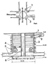
The experience in design and construction of sewage treatment systems and constructions had proved such systems necessity. It is wellknown that for such purposes main pump stations are usually build with dipping method. Today St. Petersburg and many large cities all over the world are facing the problem of metro construction connected with the lack of free territory. In connection with it we propose to build junction metro stations of St-Petersburg metro in large-sized dipping wells (Figure 1).

Figure 1 Multifunctional deep-set junction terminal (Location), (Junction terminal plan), 1, Pedestrian cross; 2, Underground garage entrance; 3, Deep-set edifice; 4, Underground garage; 5, Junction terminal stations; 6, Lift shaft.
We propose to use a construction with 66.0meters in diameter and 70.0meters high for that purpose. It will allow to organise the junction terminal in the lower part of the well. The upper part could be used for a 7-stored underground garage for 850 cars. Due to that we would save 15000square meters of the city territory. Usually the constructions of the described type are deepen into the ground for 70meters. Their cross section ranges from 2000 to 3000 sq. meters. So the contacting area between their lateral surface and the ground is from 150 to 200 thousands of sq. meters. When being used these constructions cross several (above 5) aquifer levels and greatly influence upon the surrounding buildings and geologic environment. The type and the after-effect of such influence differ from time to time. On one hand they are determined by the engineering and geological conditions of the construction site. On the other hand - by the designing and technological peculiarities of the deepen constrution and it’s building. Hence there is a problem how to exclude or minimise the above mentioned negative after-effect. To be settled this problem needs the systematic approach towards joint solving of geotechnical and engineering problems.
Today we are undertaking the works upon geo- monitoring system creation. This system is being implemented step by step in Northern and Southern sewage systems construction. The geo-monitoring system structure is based on the following subsystems.1‒4
We have large experience in implementing of different methods providing reliability and quality in deeping constructions building. Our experience shows that geo-monitoring system should be adapted to control the processes in semi-continuous mode and in real time. Some research institutes had used strained and deformed state control system for deeping wells construction. The results shoe that every deviation from the project is registered by the control instruments. However it’s a great problem to use this data for determinated process control. It is explained by the fact that it takes much time from the moment of getting the initial data to the moment of it’s analysis and issuing the recommendations for some technological steps. It is connected with the long period of time needed for data processing. Unfortunately the structural and geo - engineering conditions also change meanwhile.
Our investigations gad shown that it’s possible to provide the reliability and uniformity for edifices deeping process. It could be achieved by creating the semi-continuous interaction system for the three- dimensional ( dX, dY. d Z) and time (dt) process variables.5,6
We have taken out some estimate-theoretical and research works. As a result we have worked out and tested the complex system providing the geo- technical support for deep-set edifices deeping process. These edifices were from 50 to 70meters in diameter. They had been implemented in waste treatment facilities construction in St. Petersburg. The mentioned above system comprises three following complexes: measuring-control complex; signal estimation and transmission for process control purposes; immediate feed-back complex. The measuring-control complex provides monitoring for the SDS orientation of edifice shell and ground massive. It includes spatial orientation instruments (laser range finder, volumetric reflectors, bank angle detectors). Besides, it includes the instruments estimating ground resistance along the lateral surface of the edifice, ground lateral pressure, ground pressure under the edifice knife banquet, reinforcement stress, concrete distortion.7‒10
SDS control system provides monitoring of the following variables characteristic for the “deep-set edifice - geomass” behaviour:
Initial transformers are installed in 6 - 8 section points in edifice shell perimeter from 5th to 10th layers. E.g.: There were 86 pressure, friction temperature and other transformers installed in the deep-set edifice with 49,6 meters diameter. Strain sensors, steam pressure detectors, string hydraulic sensors and rigid string hydraulic sensors were used for contact pressure measuring.
The results of reinforcement strain and distortion
detection were used to estimate the Edifice shell SDS. String detectors and strain sensors that were stacked to the reinforce were used for that purpose. Edifice bank was detected by the bank sensors. Those sensors are based on double string gauging transformers (measuring accuracy didn’t exceed 10 sec). Semi continuous system for detectors’ indication registration includes the following instruments: portable digital lime setter, 20 channel electronic communicator, controller (stand alone interface module) Kl-20; controller remote control unit; power supply unit; wiring cables (controller, controller - communicator, power supply - controller; PC controller, power supply - battery, communicator, periodic tolling controller, communicator - sensors).
We have proposed new geo-technical methods for unique large-scale edifices. These methods are based on geo mass SDS controlling not only in the basement but also in it’s lateral surface.
Essentially the described methods and their realisation technique are as follows:
We had fulfilled several cycle calculations with Finite elements method for the ground conditions typical for St. Petersburg (Quaternary sediments 26-35meters deep, underlayed by hard Cambrian clays). As a result of computing experiment we had calculated the admissible deviation ‘dh’ from the vertical axes and non-deforming fits ‘di’ values. We have come to a conclusion that tixothropic jacket is the best possible solution in this case. It results in friction strength decrease on the marks from 16 to 47meters. Hovering stability is achieved through electroosmosis up to 16meters height and with ‘di’< 0.015. We propose dedicated method for geomass preparation to correct the bank for ‘h’ and di high values. Besides, what we propose is the discharge well design in knife and lateral surface areas.
The described above results of using geomonitoring system for large diameter deep-set edifices construction could be successfully implemented for large scale basements construction. Besides it might be used for deep-set edifices construction in hard and complicated ground conditions. Also these methods could be used for developing and reconstruction of existing underground territories in large cities.
To save city building environment we have worked out the structural geo-technological model of large scale edifice construction. This model is created considering the characteristic features of interaction between structural and technological processes on one side and engineering and geological processes on the other. Being the monitoring object the deep-set edifice is represented as a geo-technical system (GTS) - that is the interconnected and interlined assembly of technical object (TO) (the deep-set construction itself) and of geological object (GO) (the ground) Figure 2.11,12 Technical object is a steric one with the concentrated infiuence and distributed structural and technological parameters. Geologic object is an assembly of city building and geomechanical elements that might be combined corresponding to geological environment model.
GTS is influenced by a great number of factors that could be devided into three following groups:
Each vector: G,H,X, consists of numerous factors. The greater part of those factors is unknown. To determine them multidimensional distribution law for probability distribution should be defined.13 Please find bellow the equation that describes the process of deep-set edifice construction and functioning. This equation describes it in a simplified mode according to the common principals.
Where Ï is a reducted factor of target product output (by the specific volume of deep-set edifice internal volume),
R, Re, Rp - reducted expenditures (reducted costs, power and labour expenditures);
t - time of functioning.
The task for optimum GTS monitoring could be formulated in the following way: one is to find the control rules U(t) for GTS. taking into consideration a set of regulations. These regulations transfer technological and geological objects to the monitoring mode. Optimum function should have an extreme and is expressed with the following equation.14
Where P is continuous function of output variable Y and of controlling influences H, G, U
Optimum criteria for the whole period of GTS development and functioning (e.g.: deep-set well construction) is represented as a sum optimum criteria elements on each construction stage (installation and deeping).
Optimum GTS control is reduced to the step by stem To and GO variables control. The control is fulfilled according to the algorithm of optimum way of aim achievement. So our aim is to settle the problem of deeping the well shell under the optimal geo-technological conditions in the preset time or with the minimum influence upon city building environment.
Geo-technical research works include large scale laboratory experiments, quantitative modelling by Finite elements method and site testing. To simulate the conditions of deeping by Finite elements method we had used incremental ground model, based on generalised Gook principle. The relation between strain and deformation increments was computed separately for stress tensor deviation and spherical components.15
Where dSij and deij - stress and deformations tensors deviation components increments respectively;
dσср and dεcp - average stress and deformation values increments;
GT and KT - tangent modules of shape and object deformation.
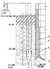
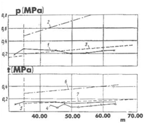
First in laboratory and then on the site we have carried out the investigation to find out the tixothropic solution features influence upon the large scale deep-set edifices deeping process. The plan of monitoring instruments location is shown in Figure 3. The results of friction and pressure strength detection are shown in Figure 4. Engineering and geological conditions of the construction site are typical for St. Petersburg city building environment. It means that the territory is formed by the grounds of Quaternary sediments 26 - 35meters deep, underlayed by semi hard and hard Cambrian clays up to the 71.0meter depth.

Figure 3 Instruments location plan on the deep- set well: 1,2, Pressure and friction sensors; 3, Reinforcement dynamometer; 4, Wiring cables; 5, Control station.

Figure 4 Pressure and friction measurements during the deeping process, 1,4,5, Experimental data; 3,6,7, Computering values for ground pressure and friction.
The well for Northern waste treatment facilities with 66.1meter diameter is designed as a monolith unite. We had included a tixothropic jacket into construction to provide the deeping process reliability. Deeping process quantitative modelling for large scale wells in the inclined layers of Cambrian clays had shown the necessity of control system for deeping process. The system included electroosmosis plant and instrumental control net.1,4,16 Electroosmosis plant comprised the electrode bell 10.5meters high mounted on the knife external surface and 45 tube electrodes. The electrodes were located along three concentric circles. The distance from the well external ring was 3,6 and 7meters. They were dipped to the 41.0 - 43.0meters height. The rectifiers were used as power supply units for DC voltage. They had provided 74 V and 3300A (Figure 5). The controlled deeping process was conducted in the following way. First the ground was electrically treated with for 1.5-3.0 hours (voltage gradient was 0.2 V per sm, current density was about 2 A/sq m. Then the well was gradually deepen. Previously the well had been motionless for several Jays (Figure 6). Preliminary electrical treatment allowed to increase the deeping rate 2.5-3.0times. The deeping rate ranged from 5 to 15sm. per minute, the electrode polarity being changed deepening rate abruptly went down, the bank was corrected and the deeping stopped.3,17. For Southern waste treatment facilities the deeping well was 51.0meter in diameter. The deeping height was 49.0meters. Anodes and cathodes were located on the knife part of the construction in interchange order. The clay solution had the access to the electrodes. As a result we had achieved deeping acceleration, bank correction and eliminating of negative influence upon city building environment.
None.
The authors declare there is no conflict of interest.

©2018 Perminov. This is an open access article distributed under the terms of the, which permits unrestricted use, distribution, and build upon your work non-commercially.