International Journal of
eISSN: 2573-2838


Research Article Volume 2 Issue 4
1Imam Khomeini International University, Iran
2University of Sistan and Baluchestan, Iran
3The University of Auckland, New Zealand
Correspondence: Maryam Roozbeh, Imam Khomeini International University, IKIU, Qazvin, Iran
Received: November 20, 2016 | Published: April 26, 2017
Citation: Keshtkar A, Roozbeh M, Sani HK, et al. Fluctuation in blood velocity under applied electromagnetic pulse fields. Int J Biosen Bioelectron. 2017;2(4):107–112. DOI: 10.15406/ijbsbe.2017.02.00029
The definition of the “Lorentz Force” comes from applying electrical and magnetic fields straight to fluid direction. This force is an elemental factor for magneto-hydrodynamic pumps. Based on energy and linear momentum conservation laws, we can derive the governing equations for our problem. Accordingly, MHD pump performance is impacted with any small fluctuation in electrically conducting fluid and current density in blood carrying arteries. After implementing constant and transient electromagnetic pulse fields, we were interested to employ finite element approach to study velocity profile and temperature distribution of the flowing blood. The novelty of this work is considering the edge effect, which was not considered in any other previous works. Results show that transient electromagnetic fields with stronger pulses increase the fluid velocity with lower fluctuations in various temperatures. Through defining an allowable criterion for temperature range, these results will be extensively applicable in drug delivery and other biomedical engineering applications.
Keywords: maxwell equations, lorentz force, edge effect, nano-particles, finite elements approach
Magneto-Hydrodynamic (MHD) theory is based on exerting perpendicular electromagnetic fields on motion of electrical conducting fluid.1-6 According to Lorentz principle, stimulating these fields lead to the appearance of a force along the fluid path.7,8 Derived force can be employed for diagnosis and treatment in different ways such as drug delivery to injured organs, drug delivery with nano-particles for invaded cancerous cells, nano-robot navigators in local surgeries and many other applications.8-12 In fact, in some cases lower velocity in drug delivery to injured locations makes it possible to have a lower drug concentration and lower treatment performance.8,13,14 Therefore,by using MHD pumps drug delivers to injured organs in higher speed and more efficiently.11 Alongside with the application of MHD pumps for simulating, pumping, sorting and mixing fluids in channels, it will be used in industry for heating and circulation, buoyancy, and rotation of liquid metals.3,15 Researches on MHD pumps showed that applying constant long-lasting electromagnetic fields increases the temperature distribution while it has a lower effect on fluid velocity.16,17 This phenomenon for bio-fluids such as blood shows itself in a more problematic scheme. In addition thermo-physical properties of blood and electromagnetic fields’ characteristics such as its transient regime and edge effects were not considered in exact form in previous studies.8,18 Figure 1 provides a schematic view for MHD pumps. In this paper, firstly, a 3-D geometry model for human artery for electromagnetic fields is simulated. Then, by using finite element method variation in blood velocity and temperature distribution were studied. In this study, results compared for both constant and pulse-transient stimulations applied with and without edge effects considerations.
Governing equations
With the assumption of constant electric field, magnetic field, blood thermo-physic properties, laminar flow and for fully developed flow we have:1-3
(1)
According to Figure 1 the electric current density of J is produced perpendicular to fluid motion which leads to a direct force parallel to fluid motion. With respect to existent magnetic field and applied electric current density in Lorentz equation (2) this value depends on fluid’s electrical conductivity σ, mean velocity V, magnetic field intensity B, and employed electric field E.1,16(2)
From the derived force in Lorentz equation, new blood velocity value can be derived from Navier-Stokes equation (3).3,17,12 Then, this new velocity value can be used to calculate J in equation.1. And consequently, new force value can be simply assessed. This recursive process continues while the velocity value in iteration number N has a very small deviation from iteration of level N-1. It is another description of convergence.1,2(3)
In Figure 2 a schematic view of a flowchart solving the coupled set of equations for this complex problem is provided.
Energy equation.4 also can be used to calculate temperature distribution in fluid flow:
(4)
In this equation ρ is considered as fluid density, CP specific heat capacity, T fluid’s temperature, and s or entropy from the below equation:(5)
With respect to current complexity among the governing equations finite element method were employed to calculate the blood velocity and temperature distribution inside the channel for constant and transient electromagnetic fields. First of all it is needed to discretize the whole model into small compartments called elements. These elements have corners for connection to other elements called as nodes. In solution process, it is required to derive the governing equations between nodes. These equations will be solved simultaneously for all nodes and leads to nodal solution for the all parts. Behavior of each element can be derived from the solution of its surrounding nodes. Eventually, physical behavior of the whole model can be considered from the whole elements of finite element model. All of the boundary conditions should be applied on nodes and elements on the boundary. If there were an element for simulation in finite element software which couple all electrical, magnetic, fluid flux and heat transfer properties and calculate the results, solution will become much convenient. However, in this condition it is better to try other methods to calculate temperature distribution and blood velocity.In this paper, by using an appropriate fluid element with relevant boundary conditions, blood velocity inside channel derives from finite element method. Then with the same process electrical and magnetic solution is achieved and distribution of electrical and magnetic fields inside blood channel obtained. It should be considered that fluid, magnetic and electric elements are required to have similar geometry and node numbers. Node locations need to be fixed in different solvers, because the results of electrical field, magnetic field and fluid velocity are gathered in equation.1 simultaneously. Each node in each stage for these parameters collecting in equation.1 and consequently in equation.2 force can be calculated (F). The assessed value is in the form of body force which can be implemented on element nodes for fluid solution to calculate nodal velocity (V).
Therefore, boundary conditions of the problem for fluid flow solution are according to:
For electrical solver simulation we have:
For magnetic solver simulation the assumption is:
And eventually the considered boundary conditions for thermal solvers are:
While the constraints in temperature leads to some limitations in exerted amplitude electrical field especially in bio-fluids such as blood. Therefore, before studying fluid velocity variation, its temperature needs to be checked.
Simulation process and materials
In order to simulate the targeted fluid, a 3-D cubic geometry in fluid direct motion (+X) with thermo-physical properties of blood is considered. For generating magnetic field two coils were used around artery each of which carrying a current electricity parallel to fluid motion in opposite directions. These two coils with reverse current directions in two sides of blood channel produce magnetic field perpendicular to blood motion (+Y). And for creating electrical field two electrodes with definite potential differences were employed in two sides of the blood channel. This potential difference in two sides of the channel produces electrical field vertical to blood motion and magnetic field (-Z). Table 1 & 2 provide some information for modeled channel geometry and thermo-physical properties of blood, respectively.
Axis X(mm) |
Axis Y(mm) |
Axis Z(mm) |
||||
Duct Dimensions |
x1=0 |
x2=14 |
y1=0 |
y2=1.5 |
z1=0 |
z2=1 |
Electrode Dimensions |
x1=7.44 |
x2=6.51 |
y1=0 |
y2=1.5 |
z1=1 |
z2=1.2 |
Coil Dimensions |
x1=7.44 |
x2=6.51 |
y1=0 |
y2=1.5 |
z1=1.4 |
z2=2.6 |
Table 1 Simulated channel dimensions with coils and electrodes
Thermo-Physical Properties of Blood |
Blood |
Plasma |
RBC |
Density ρ (kg/m3) |
1060 |
1025 |
1125 |
Viscosity µ (cp) |
3 |
1.3 |
6 |
Specific Heat Capacity Cp (J/Kg. °C) |
3750 |
- |
- |
Thermal Conductivity k (w/m.k) |
0.492±0.009 |
0.57 ±0.01 |
0.45-0.482 |
Electrical Conductivity σ (S/m) |
0.667 |
2 |
- |
Table 2 Blood thermo-physical properties4
With respect to equation.6 and small value for blood velocity (0.05 m/s), the effect of magnetic flux density in energy equation can be neglected for thermal solution. This is because there is no coupled element for thermal-electrical-fluid solver and the effect of electrical field considered lonely. In this regard, coupled element of electrical-thermal was selected in this section and the fluid velocity effect was equalized with limitation of electrical field imposed time. In fact, fluid with a defined velocity in imposes to electrical field in a specified time and then electrical field is removed in which this specific distance time (18.62 milliseconds) is measured from electrode length divided by fluid velocity (Figure 4). In fact, it is aimed to obtain the bearable electrical field for human body and velocity variation can be studied by determining its ultimate applying range.
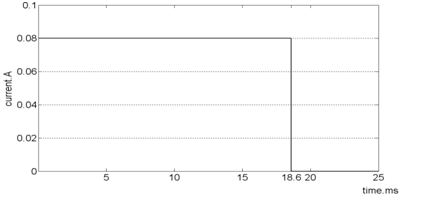
Figure 4 Current graph plotted for electrodes in order to apply constant electric fields to
fluid by without considering border impacts for temperature calculation.
With respect to pulse of Figure 4 temperature distribution is obtained and the highest acceptable value for electrical field which do not harm human body can be estimated. As the coupled element of electrical-thermal cannot accept voltage as an input, favored voltage difference can be produced by deriving electric current on two electrode tips, as it was obvious from the plotted graph in Figure 4 in vertical axis. Again with respect to the given potential electricity distribution, it is revealed that fluid movement inside channel influenced by borders impacts. Therefore, in order to consider these borders impacts it is required to alternate pulse electric field. Before blood flow pumped to the electrical field area, it is subjected to a weaker filed starting with zero and ending to its maximum level in pump opening. In crossing the pump electrical field stands on its highest value up to the pump outlet. After that this maximum value of electrical field decreases and it gradually vanishes. In order to calculate pulse acting time from zero to maximum, we need to measure channel’s margin of span which is effective in simulation of electrical field distribution and divided by blood velocity. The intended pulse is provided in Figure 5. By implementing pulse model for electric field, in fact, the effect of velocity in temperature measurement is considered. Therefore, measurement of blood temperature was considered locally and its increment due to circulation was neglected in our calculation. In this regard, as the electrical current applied on the system in a very limited time its ultimate value of electrical field can be set to a higher level of velocity. The allowable value for applied electrical field in MHD simulation for each imposing time can be measured from simulation.
Blood temperature distribution by applying constant electromagnetic field: In order to obtain the tolerable electrical field for blood in a short time, pulse currents similar to Figure 5 applied to electrodes in 0.05, 0.06, 0.07, 0.08 & 0.09 Ampere. Consequently, from the derived temperature distribution inside channel ultimate value for electrical field which could be tolerable for human body can be estimated. Figure 6 displays temperature distribution inside channel and for the range of 6.51mm<x<7.44mm for field with amplitude of 0.8A. As it is obvious from the Figure 6, after applying current in 0.036 seconds temperature rises to body level which is 319 Kelvin. In Figure 7 & 8 potential distribution and electrical field inside channel is provided by applying the given pulse in Figure 5. As it is obvious from the given results, the maximum allowable electrical field to be applied to blood in 0.039 seconds is 49260V/m. In Figure 9 temperature variation inside channel with respect to pulse field has been displayed. It is obvious from the figure that by increasing pulse time, temperature rises and by the end of applying pulse temperature decreases to body steady condition.
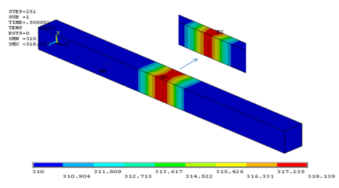
Figure 6 Temperature distribution in transient electric field in final set and for the middle cross-section.
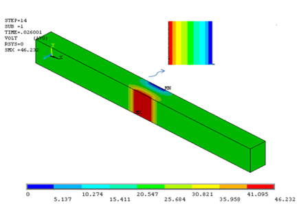
Figure 7 Potential electric field inside channel and in X= 0.0065 m section (edge effects are observable).
Velocity profile by applying constant electromagnetic field
In this section, constant electromagnetic field is applied to human artery in a long time. Therefore, its amplitude cannot be increased from 2000 V/m. By increasing this field for unlimited time, temperature highly rises.1,12 In Figure 10 the effect of electromagnetic field in velocity profile in E=350 V/m of electrical field and flux density of 0.5 to 2.5 T is provided. Approximately in 0.004 meter from the channel inlet we have fully-developed velocity profile while the maximum velocity of 0.0791 m/s in Y=0.8333mm is achieved. By variation in magnetic flux density there is no sensible deviation in velocity profile. In Figure 10 for range of electric field of 300V/m to 2000V/m and magnetic flux density of 1 (Tesla) maximum velocity variation is provided. As it is obvious from Figure 11 this range of electric field has little impact in velocity profile while it cannot be increased because of its long applying time.
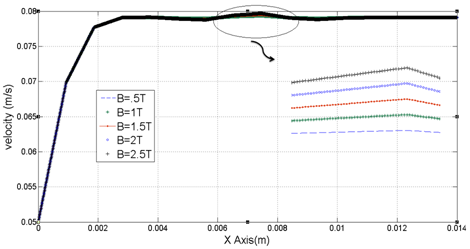
Figure 10 Velocity variation in channel length in range of X=0 to X=14mm with Y=0.666mm and Z=0.5mm with different values of flow density.
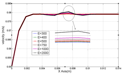
Figure 11 Velocity variation in blood channel for different long-lasting electric fields in range of X=0 to X=14mm with Y=0.666mm & Z=0.5mm.
Blood velocity profile for pulse electromagnetic field
Temperature measurement for a short time is showed that the electric field value inside channel can be increased by considering the shortness of its applying time. Therefore, pulse electric field such as Figure 12 is applied to blood channel and for this case magnetic field of 1 Tesla is considered. In this case, by employing initial conditions the system reaches to steady state condition in 3.348 seconds and then pulse field is applied. With respect to the given results in Figure 13, velocity increases remarkably. To have a better discussion on this topic variation of maximum velocity sketched in Figure 14 with applying pulse fields. By applying a transient electrical field to the blood flow in 36 milliseconds, temperature reaches to the maximum value of 318.39K. By applying pulse field of Figure 12, in 0.5 seconds temperature reaches the maximum of 317.23K (in E=49260V/m) which could cover a bigger range of electric field without any injury to human artery. By creating electrical field of 49260V/m and magnetic flux density of 1T (in pulse format 5-30) blood velocity increases to 0.0878 in 3.367 seconds. Before applying electromagnetic field maximum increment in velocity of 0.07034 is achieved and finally after steady state condition 0.070914 is achieved each of which shows that pulse filed can be applied with higher efficiency in increasing velocity profile.
Existence of constant electromagnetic fields and leads to increment in body temperature and there would be no variation in velocity profile. Therefore, temperature increment limits the electromagnetic fields. By changing in electric field (from 300V/m to 2000V/m) in 1T magnetic flow density, velocity variation is not sensible and could be neglected. It is because the source term is very small in Navier-Stokes equation. It is also observed that magnetic flux density variation (from 1T to 2.5T) with constant electric field (E=350V/m) has a little impact on blood velocity. In addition to the effect of electrical field on temperature distribution, magnetic flux density variation has a little impact and this point can be highly noticeable in biomedical application. Eventually, with respect to the given information in this paper it is revealed that applying higher electric field for a short time increases the velocity. With lower fluctuations in temperature distribution which could be extensively applicable in biomedical engineering.
We are interested to acknowledge the biomedical engineering group for their help in providing primary idea and following up with the experiments. Everyone in Imam Khomeini International University is acknowledged for their patience.
The author declares no conflict of interest.

©2017 Keshtkar, et al. This is an open access article distributed under the terms of the, which permits unrestricted use, distribution, and build upon your work non-commercially.