International Journal of
eISSN: 2573-2838


Mini Review Volume 6 Issue 4
1Qorvo Inc, USA
2Texas Tech University, USA
Correspondence: Bhargava Teja Nukala, Qorvo Inc, USA
Received: September 08, 2020 | Published: November 9, 2020
Citation: Nukala BT, Lie YC, Nguyen TQ. A brief feasibility study of wireless power transfer using strongly coupled magnetic resonance (SCMR) on cochlear implant at 11.7 MHz. Int J Biosen Bioelectron. 2020;6(4):93-97. DOI: 10.15406/ijbsbe.2020.06.00194
We report here a detailed 3-dimensional (3-D) electromagnetic (EM) simulation study on the feasibility of Wireless Power Transfer (WPT) using the strongly coupled magnetic resonance (SCMR) effect at MHz frequencies for potential biosensors applications such as cochlear implants. We have already demonstrated our SCMR results in the application of micro scale biosensors.1 In this paper we have demonstrated the use of Strongly Coupled Magnetic Resonance (SCMR) technique in cochlear implants. SCMR is very useful for higher power transfer especially in near field magnetic resonance applications. We demonstrated a method to improve the efficiency of cochlear implant coils to maximize the power efficiency at MhZ frequencies. Our results show that SCMR can improve the power efficiency by 40% compared to the traditional 2-coil system.
Cochlear Implant (CI) is one of the most popular and successful surgeries today that involves the implantation of a power-efficient electronic device with multiple electrodes inside a patient's inner ear. It is estimated that more than 150,000 patients worldwide have received CI since its beginning in the early 1970.2 The first human implant was performed by an engineer/physician team of Djourno and Eyries in 1937.3 Cochlear implants bypass the damaged hair cells in the ears by directly stimulating the auditory nerves within the cochlea with modulated electrical pulses to enable acoustic perceptions, and can, therefore, powerfully restore hearing to the patients with conductive as well as sensory-neural hearing loss.3 In another word, CI mimics functionality of a healthy cochlea by bypassing the natural hearing mechanism and directly stimulating the inner ear sensory cells of the auditory nerve by delivering electrical signals to an electrode array implanted inside the cochlea. Inductively coupled coils remain the most popular choice for wireless data and power transmission, and for CI as well. Design requirements of an inductive link for medical implant demands careful consideration of: (i) bandwidth needed to support the required data rates; (ii) power efficiency for minimum power drop through the inductive link; (iii) coupling insensitivity to coil misalignments; (iv) size of the implanted device; (v) cost and reliability, and (vi) biocompatibility. Highest data rate design may not provide high enough efficiency for power transmission so there are often conflicting requirements for design trade off. In general, wider bandwidth and high data rates are better supported at higher link frequency. On the contrary, efficient power transfer is nominally achieved using lower operating frequency. The modulation of RF signals in CI is usually of the simple amplitude shift keying (ASK) type to accommodate for the high frequency and low power requirements. The RF power amplifier (PA) of the external unit should be highly power efficient, and it is typically a switch-mode class E PA. The transmitting coil, and especially the receiving coil should be as small as possible, yet capable of high bandwidth.3 The RF transmission efficiency is negatively affected by thicker skin flap, and the current CI has about 20mW to 40mW are receivable at the internal coil with about 40% transmission efficiency.4 In practice, therefore, optimization of efficiency for inductive power transfer is highly desirable for CI.3–6 We will show our brief feasibility study on if we can improve this inductive wireless power transfer using the Strongly Coupled Magnetic Resonance (SCMR) techniques described in this paper.
The first step in the design and analysis of this CI resonance inductive link is to compute the link response at its operating frequency, where 11.7 MHz is chosen here because Cochlear Implant companies such as Advanced Bionics, Cochlear Americas and MED-EL used this 11.7MHZ frequency for transmission link.7 For a 2-coil system, the primary TX circuit is tuned in series resonance and the secondary RX coil is tuned in parallel resonance as shown in Figure 1. This demonstrate a good combination because phase of the inductor and capacitor voltage cancel at resonance and therefore a series-resonant primary network requires lower voltage swings at its input.8 Our second step in this investigation is on the design of the coils, which plays a critical role in the optimum data and power transmission. Design factors which contribute to link efficiency and voltage gain include the coupling coefficient, quality factors, coils geometry, coils dimensions, the type of wires used in the windings, and the inductance and number of turns for each coil. The circuit R’s and C’s are calculated after L’s and Q’s are known as shown from equations (1)-(6):9
1𝐶1 = 𝐿1 × 𝜔2 (1)
1𝐶2 = 𝐿2 × 𝜔 (2)
𝑅 = 𝑅1 = √𝐿1⁄𝐶1⁄𝑄1 (3)
𝑅2 = √𝐿2⁄𝐶2⁄𝑄2 (4)
𝑅4 = √𝐿2⁄𝐶2 × 𝑄2 (5)
𝐾12 = 𝑀12 × √𝐿1 × 𝐿2 (6)
Examples of CI systems are shown in Figure 2A, where there are several ways to design the TX coils and the CI system from different vendors, but the size of the RX coil is more or less fixed.7 The Rx coil should be underneath the muscle layer and the estimated skin thickness is around 0.6cm, fat ~0.1cm and muscle ~0.3cm. The casing for both the RX coil and the TX coil are made of polyethylene with some silicon but for stimulation purpose in this feasibility study to demonstrate the effectiveness of SCMR can be applied to CI and benefit it, we will just assume they are all in silicon for simplicity. Therefore, we will next considered the miniaturized TX and RX coils design setup for WPT as shown in Figure 2B.
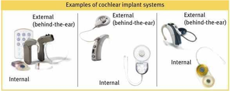
Figure 2A Examples of the CI systems.8
Both the TX/RX coils are on silicon substrates of thickness 0.1 cm. Ignoring the substrate effects, we can just extract inductance and Q of the coils from Y (1,1) only and is shown in Figure 3 & Figure 4. The equations used to extract L and Q from the designed coil. So from this design of the coils with 3.1 cm diameter, we can see the SRF is at 0.8 GHz and the max Q is occurring at around 20 MHz and the Q at 11.7 MHz is 76. Also, to verify if our coils design is reasonable and realizable, we checked the Coilcraft air core inductors and confirm that we can indeed have high Q at low frequencies >100 with SRF typically at 2GHz ((http://www.coilcraft.com/1111sq.cfm) and therefore we will use this coils design setup to continue our EM simulation of the WPT system design for CI.
The cross-sectional view of the conventional 2-coil inductive power coupling system for CI is shown in Figure 5. As stated below, Figure 5 shows the estimated thickness for skin is 0.6cm, fat 0.1cm and muscle 0.3cm, and the RX coil in this case is assumed to be lying on top of the muscle layer so the distance from the TX coil to the RX coil is at 0.7cm. There is silicon substrates for the TX coil or the RX coil of thickness 0.1cm, as the TX coil should be similar to RX coil that is enclosed in air box surrounded by plastic material. In this case as shown in Figure 5, the EM-simulated inductive power coupling is -11.5 dB, which is only 7% efficient as shown in Figure 6. Note if the RX coil is completely underneath the muscle, then the distance of the TX-RX coils separation will be increased to 1 cm as shown in Figure 5, and that can degrade the power coupling more and because of this the TX coil should be more optimized for better power transfer. The EM simulation indeed shows that in this case when the TX-RX distance is 1cm then the power transfer is reduced to -20 dB (i.e. , only 1% of the TX power transferred to the RX coil even with a perfect RX rectifier), as shown in Figure 7. Now if the TX coil thickness is increased to 1cm, we expect to get better WPT efficiency and in this case the RX coil is completely inside and underneath the muscle layer. Therefore, the L and Q simulations were performed again and the improved results are shown in Figure 8 & Figure 9.
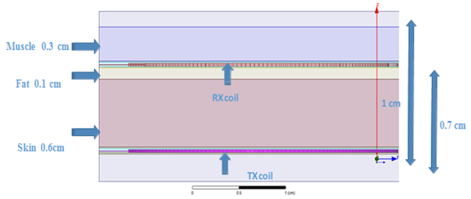
Figure 5 Cross-section of our estimated inductive WPT system with a conventional 2-coil coupling for cochlear implant.
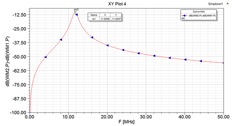
Figure 6 Simulation of the 2-coil inductive wireless power transfer for the cochlear implant system shown in Figure 5 TX coil Width is 0.1cm and Thickness/Height: 0.03cm.
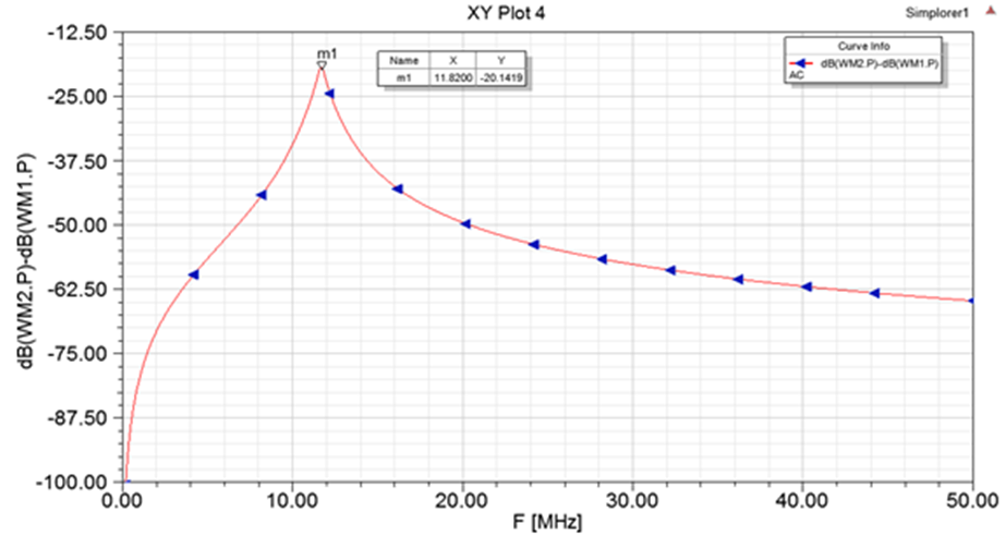
Figure 7 Simulation of inductive wireless power transfer for the 2-coil cochlear implant system when the TX-RX coils.
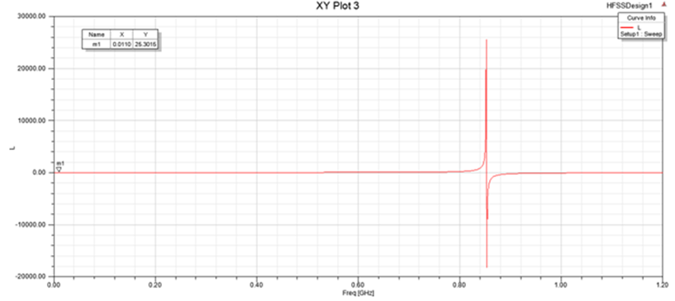
Figure 8 Simulated L of the TX coil for the same 3.1cm diameter, but here thickness increased to 1cm from 0.03cm.
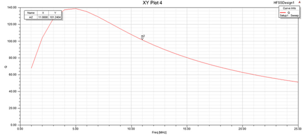
Figure 9 Simulated Q of the TX coil for the same 3.1cm diameter, but with increased thickness of 1cm.
One can see the SRF is still >0.8GHz and the extracted inductance is ~ 25nH calculated from the same equation 6.2. The Q of this TX coil is ~100 at 11.7 MHz and was calculated from the same equation 6.2. The 3D figures for the new and more realistic TX coil design is shown in Figure 10. The overall system of the cochlear implant is shown in Figure 11 with this new TX coil. This system was co-simulated in ANSYS SIMPLORER to find the coupling between TX and RX coil with a load of 125 Ohms. The power coupling is -4.34 dB, which is 36.8% efficient (Figure 12). If the same system is simulated for power transfer with a load of 232 Ohms, the power coupling is decreased to -5.80dB, which is 26.3% efficient. This clearly shows the importance of the optimal rectifier load impedance to the overall inductive 2-coil WPT efficiency Figure 13 & Figure 14. For a clear view of the layers, a zoomed in picture is shown in Figure 15 for this cochlear implant setup. So with the optimized TX/RX 2-coil WPT designs, the coupling between transmitter to receiver coil can be increased with the increase in efficiency. As shown in the results, the efficiency of the CI is improved to 36.8%. Finally, a 4-coil SCMR system is designed to increase the power efficiency of the cochlear implant. Two relay coils of diameter 3.1cm and thickness of 0.4cm are inserted between TX and RX coils. The L of the relay coils is 20nH with Q of 32. Both TX and RX coils are unchanged. And there are still no tuning caps for these two relay coils. The complete SCMR system is shown in Figure 16. The simulated wireless power transfer efficiency is -3.78 dB, meaning the 4-coil SCMR system is 41.8% efficient, 5% better than the optimized 2-coil system. This demonstrates that an optimized 4-coil SCMR design for WPT can indeed achieve >40% efficient (Figure 17).
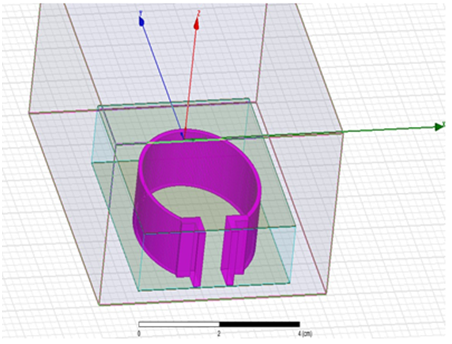
Figure 10 3D view of designed TX coil for 3.1cm diameter, thickness 1cm (TOP); TX coil with casing (Bottom).
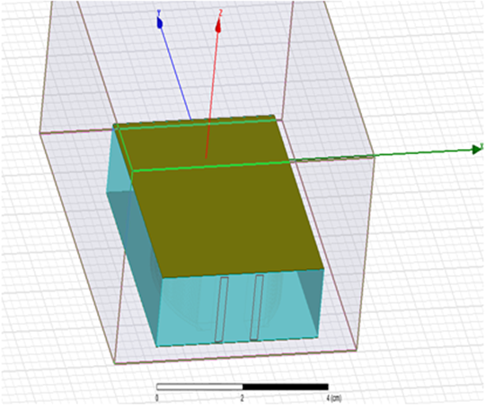
Figure 11 3D view of a more realistic 2-coil inductive WPT system for cochlear implant with TX and RX coils.
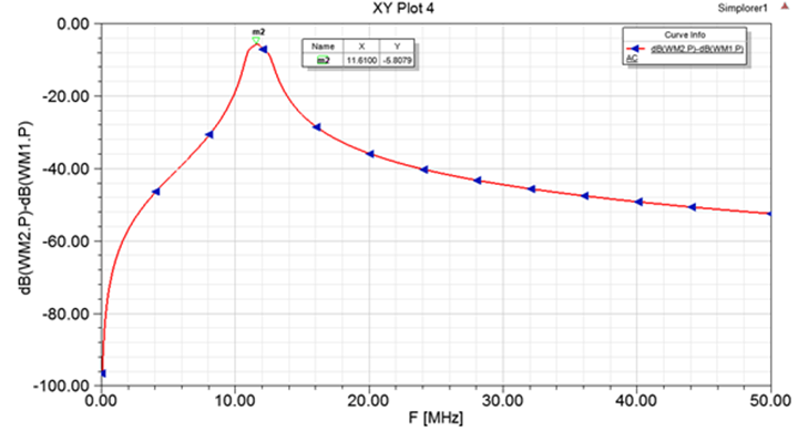
Figure 14 Co-simulation structure of the cochlear Implant system in ANSYS SIMPLORER For a clear view of the layers, a zoomed in picture is shown in Figure 15 for this cochlear implant setup.
None.
The author declares that there are no conflicts of interest.

©2020 Nukala, et al. This is an open access article distributed under the terms of the, which permits unrestricted use, distribution, and build upon your work non-commercially.