Submit manuscript...
eISSN: 2641-936X

Electrical & Electronic Technology Open Access Journal

Research Article Volume 1 Issue 2

On the analytical tuning of controllers for grid-coupled voltage source converter: frequency analysis

Cajethan M Nwosu, Cosmas U Ogbuka, Stephen E Oti

Department of Electrical Engineering, University of Nigeria, Nigeria

Correspondence: Cajethan M Nwosu, Department of Electrical Engineering, University of Nigeria, Nigeria

Received: July 22, 2017 | Published: November 8, 2017

Citation: Nwosu CM, Ogbuka CU, Oti SE. On the analytical tuning of controllers for grid-coupled voltage source converter: frequency analysis. Electric Electron Tech Open Acc J. 2017;1(1):33-41. DOI: 10.15406/eetoaj.2017.01.00007

Download PDF

Abstract

This article presents frequency analysis of controllers parameters tuning methods for grid-coupled voltage source converter. In distributed power systems, the grid-coupled voltage source converter exists in pairs linked back-to-back through a DC-link capacitor. The grid-side converter is coupled to the grid through L, LC, or LCL filter. Each of the three analytical methods of pole-zero placement, Butterworth polynomial and Internal Model Control is analyzed and tested through simulation studies in a MATLAB Simulink environment for the three filter conditions. The results so obtained shows that even as any of the three methods can be adopted for efficient control performance, the IMC method presents the best option with the addition of minor loop in the DC-link voltage control loop. In this method, the usual problem of trial and error tuning of PI controller parameters is reduced to only selecting an appropriate bandwidth frequency for the closed loop control.

Keywords: back-to-back converter, filter, controllers parameters, grid-connection, filter current, dc-link voltage

Introduction

The grid conditions determine what the output voltage of a grid connected power converters should be. Control of the output voltage of these power converters is by this condition not possible. The power converters are however, not directly connected to the grid. The conventional method to interface these converters to the grid is through filters.1,2 The duty of the filter is to reduce the current harmonics around the switching frequency of the converter. The current harmonics is capable of polluting the grid with the effect of disturbing any connected equipment.2,3 In some practical applications, the converter is not just a single three-phase converter but two back-to-back converters usually interfacing two AC systems. The two converters are linked to each other through a DC-link. The converter adjacent to the grid is in this work referred to as grid-side converter (GSC). The scope of this paper is limited to the analysis of control of the filter current and the influence of the filter on the grid and the grid-side converter with the DC-link. The filter can be a simple L, LC or LCL filter. The choice of any scheme may depend on cost, size, or dynamic performance. The filter current injected into the grid becomes the control variable since the grid voltage can’t be controlled. The filter input current is usually sensed and given back as feedback to close the control loop. Hence, the transfer function which decides the closed loop performance of the filter is the transfer function between output current and input voltage of the filter for zero grid voltage.1 Usually the current control is implemented in a dq-rotating frame in order to obtain a control with rapid dynamic response. The dq components of converter output currents are controlled using state-of-art synchronous frame PI control.4 Generally the current control is designed on per phase basis and the decoupling terms are added to allow such design. This decreases the order of system and hence simplifies controller design.5

In the past decades, PI controller has found wide applications in industrial process controls. This is majorly due to simplicity of its control law and the few tuning parameters. However, research is still on going on methods of obtaining the appropriate parameters. The researched tuning processes include but not limited to trial and error methods, feature based methods, analytical methods, optimization based methods, loop shaping methods, and auto-tuning methods.6 Among others, the analytical methods are the preferred parameter tuning process in the control of grid-connected power converters. In this paper, three kinds of analytical methods: pole-zero placement method, Butterworth polynomial method and Internal Model Control (IMC) method are each adopted for the tuning of controllers parameters for L, LC, and LCL filter interfaced grid-connected power converters. In effect pole-zero placement method and Butterworth polynomial method are similar in the sense that the primary objective of both methods is to place the closed-loop poles at the desired location in the left-half of the frequency domain. These methods, their controllers’ parameters results and the effects of the application of the parameters on the dynamic responses of the system are compared. The filter interface constitutes the PI controller process plant for the control of filter current injected into the grid.

System modeling

Models for the L, LC, and LCL filters shall be developed with a view to generating the respective transfer function for the grid current control. The transfer function which decides the closed loop performance of the filter is the transfer function between output current and input voltage of the filter for zero grid voltage.1 (Figure 1) shows a one-line diagram of the converter connected to the grid through per-phase filter inductance. vDC is the DC-link voltage; vc and ic are converter voltage and current respectively while vg and ig are grid voltage and current respectively.
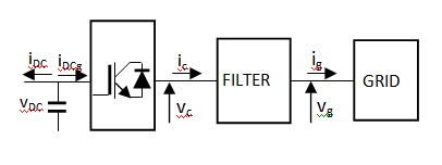
Figure 1 Per-phase simple filter as an interface between power converter and grid.

L Filter

The voltage balance across the three inductors can be written as:

[ v a v b v c ]=R[ i a i b i c ]+Lp[ i a i b i c ]+[ v a1 v b1 v c1 ] MathType@MTEF@5@5@+= feaagKart1ev2aaatCvAUfeBSjuyZL2yd9gzLbvyNv2CaerbuLwBLn hiov2DGi1BTfMBaeXatLxBI9gBaerbd9wDYLwzYbItLDharqqtubsr 4rNCHbGeaGqiVu0Je9sqqrpepC0xbbL8F4rqqrFfpeea0xe9Lq=Jc9 vqaqpepm0xbba9pwe9Q8fs0=yqaqpepae9pg0FirpepeKkFr0xfr=x fr=xb9adbaqaaeGaciGaaiaabeqaamaabaabaaGcbaWaamWaaqaabe qaaiaadAhadaWgaaWcbaGaamyyaaqabaaakeaacaWG2bWaaSbaaSqa aiaadkgaaeqaaaGcbaGaamODamaaBaaaleaacaWGJbaabeaaaaGcca GLBbGaayzxaaGaeyypa0JaamOuamaadmaaeaqabeaacaWGPbWaaSba aSqaaiaadggaaeqaaaGcbaGaamyAamaaBaaaleaacaWGIbaabeaaaO qaaiaadMgadaWgaaWcbaGaam4yaaqabaaaaOGaay5waiaaw2faaiab gUcaRiaadYeacaWGWbWaamWaaqaabeqaaiaadMgadaWgaaWcbaGaam yyaaqabaaakeaacaWGPbWaaSbaaSqaaiaadkgaaeqaaaGcbaGaamyA amaaBaaaleaacaWGJbaabeaaaaGccaGLBbGaayzxaaGaey4kaSYaam WaaqaabeqaaiaadAhadaWgaaWcbaGaamyyaiaaigdaaeqaaaGcbaGa amODamaaBaaaleaacaWGIbGaaGymaaqabaaakeaacaWG2bWaaSbaaS qaaiaadogacaaIXaaabeaaaaGccaGLBbGaayzxaaaaaa@5E48@ (1)

where va, vb, and vc are the three phase grid voltages, va1, vb1, and vc1 are the front-end converter voltages, and ia, ib, and ic are the line currents. L and R are the filter inductance and resistance, and p= d dt MathType@MTEF@5@5@+= feaagKart1ev2aaatCvAUfeBSjuyZL2yd9gzLbvyNv2CaerbuLwBLn hiov2DGi1BTfMBaeXatLxBI9gBaerbd9wDYLwzYbItLDharqqtubsr 4rNCHbGeaGqiVu0Je9sqqrpepC0xbbL8F4rqqrFfpeea0xe9Lq=Jc9 vqaqpepm0xbba9pwe9Q8fs0=yqaqpepae9pg0FirpepeKkFr0xfr=x fr=xb9adbaqaaeGaciGaaiaabeqaamaabaabaaGcbaGaamiCaiabg2 da9maalaaabaGaamizaaqaaiaadsgacaWG0baaaaaa@3ACC@ . Applying phase and rotation transformations to Eq. (1) results in:

v d =R i d +Lp i d - ω e L i q + v d1 MathType@MTEF@5@5@+= feaagKart1ev2aaatCvAUfeBSjuyZL2yd9gzLbvyNv2CaerbuLwBLn hiov2DGi1BTfMBaeXatLxBI9gBaerbd9wDYLwzYbItLDharqqtubsr 4rNCHbGeaGqiVu0Je9sqqrpepC0xbbL8F4rqqrFfpeea0xe9Lq=Jc9 vqaqpepm0xbba9pwe9Q8fs0=yqaqpepae9pg0FirpepeKkFr0xfr=x fr=xb9adbaqaaeGaciGaaiaabeqaamaabaabaaGcbaGaamODamaaBa aaleaacaWGKbaabeaakiabg2da9iaadkfacaWGPbWaaSbaaSqaaiaa dsgaaeqaaOGaey4kaSIaamitaiaadchacaWGPbWaaSbaaSqaaiaads gaaeqaaGqaaOGaa8xlaiabeM8a3naaBaaaleaacaWGLbaabeaakiaa dYeacaWGPbWaaSbaaSqaaiaadghaaeqaaOGaey4kaSIaamODamaaBa aaleaacaWGKbGaaGymaaqabaaaaa@4AEB@ (2)

v q =R i q +Lp i q + ω e L i d + v q1 MathType@MTEF@5@5@+= feaagKart1ev2aaatCvAUfeBSjuyZL2yd9gzLbvyNv2CaerbuLwBLn hiov2DGi1BTfMBaeXatLxBI9gBaerbd9wDYLwzYbItLDharqqtubsr 4rNCHbGeaGqiVu0Je9sqqrpepC0xbbL8F4rqqrFfpeea0xe9Lq=Jc9 vqaqpepm0xbba9pwe9Q8fs0=yqaqpepae9pg0FirpepeKkFr0xfr=x fr=xb9adbaqaaeGaciGaaiaabeqaamaabaabaaGcbaGaamODamaaBa aaleaacaWGXbaabeaakiabg2da9iaadkfacaWGPbWaaSbaaSqaaiaa dghaaeqaaOGaey4kaSIaamitaiaadchacaWGPbWaaSbaaSqaaiaadg haaeqaaOGaey4kaSIaeqyYdC3aaSbaaSqaaiaadwgaaeqaaOGaamit aiaadMgadaWgaaWcbaGaamizaaqabaGccqGHRaWkcaWG2bWaaSbaaS qaaiaadghacaaIXaaabeaaaaa@4B3D@ (3)

vd and vq, id and iq, and vd1 and vq1 are the d- and q-axis components of the grid voltages, line currents, and front-end converter voltages respectively. The terms ωeLid and ωeLiq cause a cross-coupling of the d- and q-axis, while the last terms are the d- and q-axis converter terminal voltages. The system is said to be coupled because the inductance matrix is not diagonal. This means that any changes in voltage component in d- or q-axis results in changes in both current components. The third and the last terms are treated as disturbances on the output. The PI controller tracks the id and iq errors to give vd and vq respectively. To ensure good tracking of these currents, the cross-related flux terms are added to vd and vq to obtain the reference voltages. The dynamics of the d-q reference frame are:

Lp i d = v d R i d + ω e L i q + v d1 MathType@MTEF@5@5@+= feaagKart1ev2aaatCvAUfeBSjuyZL2yd9gzLbvyNv2CaerbuLwBLn hiov2DGi1BTfMBaeXatLxBI9gBaerbd9wDYLwzYbItLDharqqtubsr 4rNCHbGeaGqiVu0Je9sqqrpepC0xbbL8F4rqqrFfpeea0xe9Lq=Jc9 vqaqpepm0xbba9pwe9Q8fs0=yqaqpepae9pg0FirpepeKkFr0xfr=x fr=xb9adbaqaaeGaciGaaiaabeqaamaabaabaaGcbaGaamitaiaadc hacaWGPbWaaSbaaSqaaiaadsgaaeqaaOGaeyypa0JaamODamaaBaaa leaacaWGKbaabeaakiabgkHiTiaadkfacaWGPbWaaSbaaSqaaiaads gaaeqaaOGaey4kaSIaeqyYdC3aaSbaaSqaaiaadwgaaeqaaOGaamit aiaadMgadaWgaaWcbaGaamyCaaqabaGccqGHRaWkcaWG2bWaaSbaaS qaaiaadsgacaaIXaaabeaaaaa@4B21@ (4)

Lp i q = v q R i q ω e L i d + v q1 MathType@MTEF@5@5@+= feaagKart1ev2aaatCvAUfeBSjuyZL2yd9gzLbvyNv2CaerbuLwBLn hiov2DGi1BTfMBaeXatLxBI9gBaerbd9wDYLwzYbItLDharqqtubsr 4rNCHbGeaGqiVu0Je9sqqrpepC0xbbL8F4rqqrFfpeea0xe9Lq=Jc9 vqaqpepm0xbba9pwe9Q8fs0=yqaqpepae9pg0FirpepeKkFr0xfr=x fr=xb9adbaqaaeGaciGaaiaabeqaamaabaabaaGcbaGaamitaiaadc hacaWGPbWaaSbaaSqaaiaadghaaeqaaOGaeyypa0JaamODamaaBaaa leaacaWGXbaabeaakiabgkHiTiaadkfacaWGPbWaaSbaaSqaaiaadg haaeqaaOGaeyOeI0IaeqyYdC3aaSbaaSqaaiaadwgaaeqaaOGaamit aiaadMgadaWgaaWcbaGaamizaaqabaGccqGHRaWkcaWG2bWaaSbaaS qaaiaadghacaaIXaaabeaaaaa@4B53@ (5)

The transfer function from v dq MathType@MTEF@5@5@+= feaagKart1ev2aaatCvAUfeBSjuyZL2yd9gzLbvyNv2CaerbuLwBLn hiov2DGi1BTfMBaeXatLxBI9gBaerbd9wDYLwzYbItLDharqqtubsr 4rNCHbGeaGqiVu0Je9sqqrpepC0xbbL8F4rqqrFfpeea0xe9Lq=Jc9 vqaqpepm0xbba9pwe9Q8fs0=yqaqpepae9pg0FirpepeKkFr0xfr=x fr=xb9adbaqaaeGaciGaaiaabeqaamaabaabaaGcbaGaamODamaaBa aaleaacaWGKbGaamyCaaqabaaaaa@38FC@ as input to i dq MathType@MTEF@5@5@+= feaagKart1ev2aaatCvAUfeBSjuyZL2yd9gzLbvyNv2CaerbuLwBLn hiov2DGi1BTfMBaeXatLxBI9gBaerbd9wDYLwzYbItLDharqqtubsr 4rNCHbGeaGqiVu0Je9sqqrpepC0xbbL8F4rqqrFfpeea0xe9Lq=Jc9 vqaqpepm0xbba9pwe9Q8fs0=yqaqpepae9pg0FirpepeKkFr0xfr=x fr=xb9adbaqaaeGaciGaaiaabeqaamaabaabaaGcbaGaamyAamaaBa aaleaacaWGKbGaamyCaaqabaaaaa@38EF@ as output yields:

G(p)= i d (p) v d (p) = i q (p) v q (p) = 1 pL+R MathType@MTEF@5@5@+= feaagKart1ev2aaatCvAUfeBSjuyZL2yd9gzLbvyNv2CaerbuLwBLn hiov2DGi1BTfMBaeXatLxBI9gBaerbd9wDYLwzYbItLDharqqtubsr 4rNCHbGeaGqiVu0Je9sqqrpepC0xbbL8F4rqqrFfpeea0xe9Lq=Jc9 vqaqpepm0xbba9pwe9Q8fs0=yqaqpepae9pg0FirpepeKkFr0xfr=x fr=xb9adbaqaaeGaciGaaiaabeqaamaabaabaaGcbaGaam4raiaacI cacaWGWbGaaiykaiabg2da9maalaaabaGaamyAamaaBaaaleaacaWG KbaabeaakiaacIcacaWGWbGaaiykaaqaaiaadAhadaWgaaWcbaGaam izaaqabaGccaGGOaGaamiCaiaacMcaaaGaeyypa0ZaaSaaaeaacaWG PbWaaSbaaSqaaiaadghaaeqaaOGaaiikaiaadchacaGGPaaabaGaam ODamaaBaaaleaacaWGXbaabeaakiaacIcacaWGWbGaaiykaaaacqGH 9aqpdaWcaaqaaiaaigdaaeaacaWGWbGaamitaiabgUcaRiaadkfaaa aaaa@522C@ (6)

LC Filter

The filter capacitor in an LC filter provides a low-impedance path for the high frequency PWM ripple current and, thus, attenuates the content of current ripple in the utility current.7 For a balanced three-phase system, the d-q dynamic equations for the grid current control are same as Eqns. (4) and (5). On the assumption that the parasitic grid impedances are neglected, the transfer function of grid current to inverter voltage is same for L and LC filters. Therefore, the size of inductor does not change from L to LC filter.

LCL Filter

In order to obtain the transfer function of the LCL filter, the one phase electrical diagram in (Figure 2) is considered. The subscripts ‘c’ and ‘g’ denote converter-side and grid-side components respectively. The components of the filter on each phase are considered to be identical, so the circuit below is suitable for the other two phases. Using Kirchoff’s laws, the filter model in s-plane can be written with the following equations:8

i c i cf i g =0 MathType@MTEF@5@5@+= feaagKart1ev2aaatCvAUfeBSjuyZL2yd9gzLbvyNv2CaerbuLwBLn hiov2DGi1BTfMBaeXatLxBI9gBaerbd9wDYLwzYbItLDharqqtubsr 4rNCHbGeaGqiVu0Je9sqqrpepC0xbbL8F4rqqrFfpeea0xe9Lq=Jc9 vqaqpepm0xbba9pwe9Q8fs0=yqaqpepae9pg0FirpepeKkFr0xfr=x fr=xb9adbaqaaeGaciGaaiaabeqaamaabaabaaGcbaGaamyAamaaBa aaleaacaWGJbaabeaakiabgkHiTiaadMgadaWgaaWcbaGaam4yaiaa dAgaaeqaaOGaeyOeI0IaamyAamaaBaaaleaacaWGNbaabeaakiabg2 da9iaaicdaaaa@40A3@ (7)

v c v cf = i c (p L c + R c ) MathType@MTEF@5@5@+= feaagKart1ev2aaatCvAUfeBSjuyZL2yd9gzLbvyNv2CaerbuLwBLn hiov2DGi1BTfMBaeXatLxBI9gBaerbd9wDYLwzYbItLDharqqtubsr 4rNCHbGeaGqiVu0Je9sqqrpepC0xbbL8F4rqqrFfpeea0xe9Lq=Jc9 vqaqpepm0xbba9pwe9Q8fs0=yqaqpepae9pg0FirpepeKkFr0xfr=x fr=xb9adbaqaaeGaciGaaiaabeqaamaabaabaaGcbaGaamODamaaBa aaleaacaWGJbaabeaakiabgkHiTiaadAhadaWgaaWcbaGaam4yaiaa dAgaaeqaaOGaeyypa0JaamyAamaaBaaaleaacaWGJbaabeaakiaacI cacaWGWbGaamitamaaBaaaleaacaWGJbaabeaakiabgUcaRiaadkfa daWgaaWcbaGaam4yaaqabaGccaGGPaaaaa@4626@ (8)

v cf v g = i g (p L g + R g ) MathType@MTEF@5@5@+= feaagKart1ev2aaatCvAUfeBSjuyZL2yd9gzLbvyNv2CaerbuLwBLn hiov2DGi1BTfMBaeXatLxBI9gBaerbd9wDYLwzYbItLDharqqtubsr 4rNCHbGeaGqiVu0Je9sqqrpepC0xbbL8F4rqqrFfpeea0xe9Lq=Jc9 vqaqpepm0xbba9pwe9Q8fs0=yqaqpepae9pg0FirpepeKkFr0xfr=x fr=xb9adbaqaaeGaciGaaiaabeqaamaabaabaaGcbaGaamODamaaBa aaleaacaWGJbGaamOzaaqabaGccqGHsislcaWG2bWaaSbaaSqaaiaa dEgaaeqaaOGaeyypa0JaamyAamaaBaaaleaacaWGNbaabeaakiaacI cacaWGWbGaamitamaaBaaaleaacaWGNbaabeaakiabgUcaRiaadkfa daWgaaWcbaGaam4zaaqabaGccaGGPaaaaa@4636@ (9)

v cf = i cf ( 1 p C f ) MathType@MTEF@5@5@+= feaagKart1ev2aaatCvAUfeBSjuyZL2yd9gzLbvyNv2CaerbuLwBLn hiov2DGi1BTfMBaeXatLxBI9gBaerbd9wDYLwzYbItLDharqqtubsr 4rNCHbGeaGqiVu0Je9sqqrpepC0xbbL8F4rqqrFfpeea0xe9Lq=Jc9 vqaqpepm0xbba9pwe9Q8fs0=yqaqpepae9pg0FirpepeKkFr0xfr=x fr=xb9adbaqaaeGaciGaaiaabeqaamaabaabaaGcbaGaamODamaaBa aaleaacaWGJbGaamOzaaqabaGccqGH9aqpcaWGPbWaaSbaaSqaaiaa dogacaWGMbaabeaakiaacIcadaWcaaqaaiaaigdaaeaacaWGWbGaam 4qamaaBaaaleaacaWGMbaabeaaaaGccaGGPaaaaa@41F9@ (10)

In the mathematical analysis of the transfer function, the grid voltage is assumed to be an ideal voltage source and it represents a short circuit for harmonic frequencies, it is therefore set to zero: vg = 0.
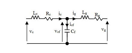
Figure 2 One phase electrical circuit of an LCL filter.

From equations (9) and (10), the following relation can be written:

i g (p L g + R g )= i cf ( 1 p C f ) MathType@MTEF@5@5@+= feaagKart1ev2aaatCvAUfeBSjuyZL2yd9gzLbvyNv2CaerbuLwBLn hiov2DGi1BTfMBaeXatLxBI9gBaerbd9wDYLwzYbItLDharqqtubsr 4rNCHbGeaGqiVu0Je9sqqrpepC0xbbL8F4rqqrFfpeea0xe9Lq=Jc9 vqaqpepm0xbba9pwe9Q8fs0=yqaqpepae9pg0FirpepeKkFr0xfr=x fr=xb9adbaqaaeGaciGaaiaabeqaamaabaabaaGcbaGaamyAamaaBa aaleaacaWGNbaabeaakiaacIcacaWGWbGaamitamaaBaaaleaacaWG NbaabeaakiabgUcaRiaadkfadaWgaaWcbaGaam4zaaqabaGccaGGPa Gaeyypa0JaamyAamaaBaaaleaacaWGJbGaamOzaaqabaGccaGGOaWa aSaaaeaacaaIXaaabaGaamiCaiaadoeadaWgaaWcbaGaamOzaaqaba aaaOGaaiykaaaa@4821@ (11)

from which we obtain:

i cf = i g ( p 2 C f L g +p C f R g ) MathType@MTEF@5@5@+= feaagKart1ev2aaatCvAUfeBSjuyZL2yd9gzLbvyNv2CaerbuLwBLn hiov2DGi1BTfMBaeXatLxBI9gBaerbd9wDYLwzYbItLDharqqtubsr 4rNCHbGeaGqiVu0Je9sqqrpepC0xbbL8F4rqqrFfpeea0xe9Lq=Jc9 vqaqpepm0xbba9pwe9Q8fs0=yqaqpepae9pg0FirpepeKkFr0xfr=x fr=xb9adbaqaaeGaciGaaiaabeqaamaabaabaaGcbaGaamyAamaaBa aaleaacaWGJbGaamOzaaqabaGccqGH9aqpcaWGPbWaaSbaaSqaaiaa dEgaaeqaaOGaaiikaiaadchadaahaaWcbeqaaiaaikdaaaGccaWGdb WaaSbaaSqaaiaadAgaaeqaaOGaamitamaaBaaaleaacaWGNbaabeaa kiabgUcaRiaadchacaWGdbWaaSbaaSqaaiaadAgaaeqaaOGaamOuam aaBaaaleaacaWGNbaabeaakiaacMcaaaa@48D9@ (12)

Equation (8) can be re-written as:

v c = v cf + i c (p L c + R c ) MathType@MTEF@5@5@+= feaagKart1ev2aaatCvAUfeBSjuyZL2yd9gzLbvyNv2CaerbuLwBLn hiov2DGi1BTfMBaeXatLxBI9gBaerbd9wDYLwzYbItLDharqqtubsr 4rNCHbGeaGqiVu0Je9sqqrpepC0xbbL8F4rqqrFfpeea0xe9Lq=Jc9 vqaqpepm0xbba9pwe9Q8fs0=yqaqpepae9pg0FirpepeKkFr0xfr=x fr=xb9adbaqaaeGaciGaaiaabeqaamaabaabaaGcbaGaamODamaaBa aaleaacaWGJbaabeaakiabg2da9iaadAhadaWgaaWcbaGaam4yaiaa dAgaaeqaaOGaey4kaSIaamyAamaaBaaaleaacaWGJbaabeaakiaacI cacaWGWbGaamitamaaBaaaleaacaWGJbaabeaakiabgUcaRiaadkfa daWgaaWcbaGaam4yaaqabaGccaGGPaaaaa@461B@ (13)

By introducing (9), (7) and then (12) into (13), the converter voltage can be written as:

v c = i g (p L g + R g )+( i g + i cf )(p L c + R c ) = i g (p L g + R g )+( i g + i g { p 2 C f L g +p C f R g })(p L c + R c ) MathType@MTEF@5@5@+= feaagKart1ev2aaatCvAUfeBSjuyZL2yd9gzLbvyNv2CaerbuLwBLn hiov2DGi1BTfMBaeXatLxBI9gBaerbd9wDYLwzYbItLDharqqtubsr 4rNCHbGeaGqiVu0Je9sqqrpepC0xbbL8F4rqqrFfpeea0xe9Lq=Jc9 vqaqpepm0xbba9pwe9Q8fs0=yqaqpepae9pg0FirpepeKkFr0xfr=x fr=xb9adbaqaaeGaciGaaiaabeqaamaabaabaaGceaqabeaacaWG2b WaaSbaaSqaaiaadogaaeqaaOGaeyypa0JaamyAamaaBaaaleaacaWG NbaabeaakiaacIcacaWGWbGaamitamaaBaaaleaacaWGNbaabeaaki abgUcaRiaadkfadaWgaaWcbaGaam4zaaqabaGccaGGPaGaey4kaSIa aiikaiaadMgadaWgaaWcbaGaam4zaaqabaGccqGHRaWkcaWGPbWaaS baaSqaaiaadogacaWGMbaabeaakiaacMcacaGGOaGaamiCaiaadYea daWgaaWcbaGaam4yaaqabaGccqGHRaWkcaWGsbWaaSbaaSqaaiaado gaaeqaaOGaaiykaaqaaiaaywW7cqGH9aqpcaWGPbWaaSbaaSqaaiaa dEgaaeqaaOGaaiikaiaadchacaWGmbWaaSbaaSqaaiaadEgaaeqaaO Gaey4kaSIaamOuamaaBaaaleaacaWGNbaabeaakiaacMcacqGHRaWk caGGOaGaamyAamaaBaaaleaacaWGNbaabeaakiabgUcaRiaadMgada WgaaWcbaGaam4zaaqabaGccaGG7bGaamiCamaaCaaaleqabaGaaGOm aaaakiaadoeadaWgaaWcbaGaamOzaaqabaGccaWGmbWaaSbaaSqaai aadEgaaeqaaOGaey4kaSIaamiCaiaadoeadaWgaaWcbaGaamOzaaqa baGccaWGsbWaaSbaaSqaaiaadEgaaeqaaOGaaiyFaiaacMcacaGGOa GaamiCaiaadYeadaWgaaWcbaGaam4yaaqabaGccqGHRaWkcaWGsbWa aSbaaSqaaiaadogaaeqaaOGaaiykaaaaaa@790E@ (14)

MathType@MTEF@5@5@+= feaagKart1ev2aaatCvAUfeBSjuyZL2yd9gzLbvyNv2CaerbuLwBLn hiov2DGi1BTfMBaeXatLxBI9gBaerbd9wDYLwzYbItLDharqqtubsr 4rNCHbGeaGqiVu0Je9sqqrpepC0xbbL8F4rqqrFfpeea0xe9Lq=Jc9 vqaqpepm0xbba9pwe9Q8fs0=yqaqpepae9pg0FirpepeKkFr0xfr=x fr=xb9adbaqaaeGaciGaaiaabeqaamaabaabaaGcbaGaeyO0H4naaa@3853@ v c = i g (p L g + R g +p L c + R c +( p 2 C f L g +p C f R g )(p L c + R c )) MathType@MTEF@5@5@+= feaagKart1ev2aaatCvAUfeBSjuyZL2yd9gzLbvyNv2CaerbuLwBLn hiov2DGi1BTfMBaeXatLxBI9gBaerbd9wDYLwzYbItLDharqqtubsr 4rNCHbGeaGqiVu0Je9sqqrpepC0xbbL8F4rqqrFfpeea0xe9Lq=Jc9 vqaqpepm0xbba9pwe9Q8fs0=yqaqpepae9pg0FirpepeKkFr0xfr=x fr=xb9adbaqaaeGaciGaaiaabeqaamaabaabaaGcbaGaamODamaaBa aaleaacaWGJbaabeaakiabg2da9iaadMgadaWgaaWcbaGaam4zaaqa baGccaGGOaGaamiCaiaadYeadaWgaaWcbaGaam4zaaqabaGccqGHRa WkcaWGsbWaaSbaaSqaaiaadEgaaeqaaOGaey4kaSIaamiCaiaadYea daWgaaWcbaGaam4yaaqabaGccqGHRaWkcaWGsbWaaSbaaSqaaiaado gaaeqaaOGaey4kaSIaaiikaiaadchadaahaaWcbeqaaiaaikdaaaGc caWGdbWaaSbaaSqaaiaadAgaaeqaaOGaamitamaaBaaaleaacaWGNb aabeaakiabgUcaRiaadchacaWGdbWaaSbaaSqaaiaadAgaaeqaaOGa amOuamaaBaaaleaacaWGNbaabeaakiaacMcacaGGOaGaamiCaiaadY eadaWgaaWcbaGaam4yaaqabaGccqGHRaWkcaWGsbWaaSbaaSqaaiaa dogaaeqaaOGaaiykaiaacMcaaaa@5DAA@ (15)

The transfer function of the filter can be obtained as:

H(p)= i g v c = 1 p 3 L g L c C f + p 2 ( L g R c C f + L c R g )+p( L g + L c + R g R c C f )+ R g + R c MathType@MTEF@5@5@+= feaagKart1ev2aaatCvAUfeBSjuyZL2yd9gzLbvyNv2CaerbuLwBLn hiov2DGi1BTfMBaeXatLxBI9gBaerbd9wDYLwzYbItLDharqqtubsr 4rNCHbGeaGqiVu0Je9sqqrpepC0xbbL8F4rqqrFfpeea0xe9Lq=Jc9 vqaqpepm0xbba9pwe9Q8fs0=yqaqpepae9pg0FirpepeKkFr0xfr=x fr=xb9adbaqaaeGaciGaaiaabeqaamaabaabaaGcbaGaamisaiaacI cacaWGWbGaaiykaiabg2da9maalaaabaGaamyAamaaBaaaleaacaWG NbaabeaaaOqaaiaadAhadaWgaaWcbaGaam4yaaqabaaaaOGaeyypa0 ZaaSaaaeaacaaIXaaabaGaamiCamaaCaaaleqabaGaaG4maaaakiaa dYeadaWgaaWcbaGaam4zaaqabaGccaWGmbWaaSbaaSqaaiaadogaae qaaOGaam4qamaaBaaaleaacaWGMbaabeaakiabgUcaRiaadchadaah aaWcbeqaaiaaikdaaaGccaGGOaGaamitamaaBaaaleaacaWGNbaabe aakiaadkfadaWgaaWcbaGaam4yaaqabaGccaWGdbWaaSbaaSqaaiaa dAgaaeqaaOGaey4kaSIaamitamaaBaaaleaacaWGJbaabeaakiaadk fadaWgaaWcbaGaam4zaaqabaGccaGGPaGaey4kaSIaamiCaiaacIca caWGmbWaaSbaaSqaaiaadEgaaeqaaOGaey4kaSIaamitamaaBaaale aacaWGJbaabeaakiabgUcaRiaadkfadaWgaaWcbaGaam4zaaqabaGc caWGsbWaaSbaaSqaaiaadogaaeqaaOGaam4qamaaBaaaleaacaWGMb aabeaakiaacMcacqGHRaWkcaWGsbWaaSbaaSqaaiaadEgaaeqaaOGa ey4kaSIaamOuamaaBaaaleaacaWGJbaabeaaaaaaaa@6AE8@ (16)

The transfer function of equation (16) is particularly useful for stability and harmonic analysis of LCL filter. For the design of the controller, the filter capacitor is neglected to obtain the d-q reference frame dynamic equations similar to (4) and (5) as:

L T p i d = v d R T i d + ω e L T i q + v d1 MathType@MTEF@5@5@+= feaagKart1ev2aaatCvAUfeBSjuyZL2yd9gzLbvyNv2CaerbuLwBLn hiov2DGi1BTfMBaeXatLxBI9gBaerbd9wDYLwzYbItLDharqqtubsr 4rNCHbGeaGqiVu0Je9sqqrpepC0xbbL8F4rqqrFfpeea0xe9Lq=Jc9 vqaqpepm0xbba9pwe9Q8fs0=yqaqpepae9pg0FirpepeKkFr0xfr=x fr=xb9adbaqaaeGaciGaaiaabeqaamaabaabaaGcbaGaamitamaaBa aaleaacaWGubaabeaakiaadchacaWGPbWaaSbaaSqaaiaadsgaaeqa aOGaeyypa0JaamODamaaBaaaleaacaWGKbaabeaakiabgkHiTiaadk fadaWgaaWcbaGaamivaaqabaGccaWGPbWaaSbaaSqaaiaadsgaaeqa aOGaey4kaSIaeqyYdC3aaSbaaSqaaiaadwgaaeqaaOGaamitamaaBa aaleaacaWGubaabeaakiaadMgadaWgaaWcbaGaamyCaaqabaGccqGH RaWkcaWG2bWaaSbaaSqaaiaadsgacaaIXaaabeaaaaa@4E4E@ (17)

L T p i q = v q R T i q ω e L T i d + v q1 MathType@MTEF@5@5@+= feaagKart1ev2aaatCvAUfeBSjuyZL2yd9gzLbvyNv2CaerbuLwBLn hiov2DGi1BTfMBaeXatLxBI9gBaerbd9wDYLwzYbItLDharqqtubsr 4rNCHbGeaGqiVu0Je9sqqrpepC0xbbL8F4rqqrFfpeea0xe9Lq=Jc9 vqaqpepm0xbba9pwe9Q8fs0=yqaqpepae9pg0FirpepeKkFr0xfr=x fr=xb9adbaqaaeGaciGaaiaabeqaamaabaabaaGcbaGaamitamaaBa aaleaacaWGubaabeaakiaadchacaWGPbWaaSbaaSqaaiaadghaaeqa aOGaeyypa0JaamODamaaBaaaleaacaWGXbaabeaakiabgkHiTiaadk fadaWgaaWcbaGaamivaaqabaGccaWGPbWaaSbaaSqaaiaadghaaeqa aOGaeyOeI0IaeqyYdC3aaSbaaSqaaiaadwgaaeqaaOGaamitamaaBa aaleaacaWGubaabeaakiaadMgadaWgaaWcbaGaamizaaqabaGccqGH RaWkcaWG2bWaaSbaaSqaaiaadghacaaIXaaabeaaaaa@4E80@ (18)

where LT = Lc + Lg, and RT = Rc + Rg.

The system plant is obtained as:

G(p)= i d (p) v d (p) = i q (p) v q (p) = 1 p L T + R T MathType@MTEF@5@5@+= feaagKart1ev2aaatCvAUfeBSjuyZL2yd9gzLbvyNv2CaerbuLwBLn hiov2DGi1BTfMBaeXatLxBI9gBaerbd9wDYLwzYbItLDharqqtubsr 4rNCHbGeaGqiVu0Je9sqqrpepC0xbbL8F4rqqrFfpeea0xe9Lq=Jc9 vqaqpepm0xbba9pwe9Q8fs0=yqaqpepae9pg0FirpepeKkFr0xfr=x fr=xb9adbaqaaeGaciGaaiaabeqaamaabaabaaGcbaGaam4raiaacI cacaWGWbGaaiykaiabg2da9maalaaabaGaamyAamaaBaaaleaacaWG KbaabeaakiaacIcacaWGWbGaaiykaaqaaiaadAhadaWgaaWcbaGaam izaaqabaGccaGGOaGaamiCaiaacMcaaaGaeyypa0ZaaSaaaeaacaWG PbWaaSbaaSqaaiaadghaaeqaaOGaaiikaiaadchacaGGPaaabaGaam ODamaaBaaaleaacaWGXbaabeaakiaacIcacaWGWbGaaiykaaaacqGH 9aqpdaWcaaqaaiaaigdaaeaacaWGWbGaamitamaaBaaaleaacaWGub aabeaakiabgUcaRiaadkfadaWgaaWcbaGaamivaaqabaaaaaaa@5440@ (19)

Controller’s design

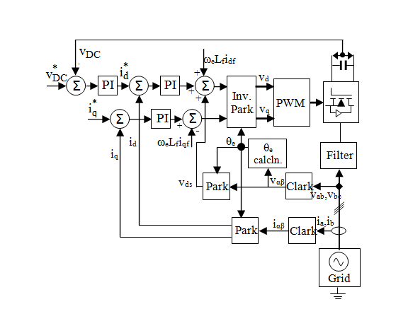
The control of the grid-side converter consists of a fast inner current control loop, which controls the current through the line inductance, and an outer slower control loops that regulate the DC-link voltage and the reactive power exchanged between the GSC and the grid. The structure of the d-q current-control, DC-link voltage control and the reactive power exchange control loops is shown in Figure 3. For unity power factor, the reactive power reference current i q * MathType@MTEF@5@5@+= feaagKart1ev2aaatCvAUfeBSjuyZL2yd9gzLbvyNv2CaerbuLwBLn hiov2DGi1BTfMBaeXatLxBI9gBaerbd9wDYLwzYbItLDharqqtubsr 4rNCHbGeaGqiVu0Je9sqqrpepC0xbbL8F4rqqrFfpeea0xe9Lq=Jc9 vqaqpepm0xbba9pwe9Q8fs0=yqaqpepae9pg0FirpepeKkFr0xfr=x fr=xb9adbaqaaeGaciGaaiaabeqaamaabaabaaGcbaGaamyAamaaDa aaleaacaWGXbaabaGaaiOkaaaaaaa@38B5@ is set to zero.

Figure 3 Current-control loop of grid-side converter.

Current controller

The term ωeLidq in Figure 3 is the d-q rotational emfs which appear as cross-coupling terms due to the transformation. The transfer function of the PI controller is given by:

C(p)=( k pdq + k idq p )= k pdq ( 1+ 1 p T i ) MathType@MTEF@5@5@+= feaagKart1ev2aaatCvAUfeBSjuyZL2yd9gzLbvyNv2CaerbuLwBLn hiov2DGi1BTfMBaeXatLxBI9gBaerbd9wDYLwzYbItLDharqqtubsr 4rNCHbGeaGqiVu0Je9sqqrpepC0xbbL8F4rqqrFfpeea0xe9Lq=Jc9 vqaqpepm0xbba9pwe9Q8fs0=yqaqpepae9pg0FirpepeKkFr0xfr=x fr=xb9adbaqaaeGaciGaaiaabeqaamaabaabaaGcbaGaam4qaiaacI cacaWGWbGaaiykaiabg2da9maabmaabaGaam4AamaaBaaaleaacaWG WbGaamizaiaadghaaeqaaOGaey4kaSYaaSaaaeaacaWGRbWaaSbaaS qaaiaadMgacaWGKbGaamyCaaqabaaakeaacaWGWbaaaaGaayjkaiaa wMcaaiabg2da9iaadUgadaWgaaWcbaGaamiCaiaadsgacaWGXbaabe aakmaabmaabaGaaGymaiabgUcaRmaalaaabaGaaGymaaqaaiaadcha caWGubWaaSbaaSqaaiaadMgaaeqaaaaaaOGaayjkaiaawMcaaaaa@5152@ (20)

where kpdq is the d and q components proportional gain, kidq is the integral gain of the d and q components controllers, and Ti is the integration time obtained as the ratio of the proportional gain to the integral gain. The representations of d-q in the gains mean that the d and q axis currents are controlled via independent regulators.

The PI current controller in each axis generates the control signals v d ref MathType@MTEF@5@5@+= feaagKart1ev2aaatCvAUfeBSjuyZL2yd9gzLbvyNv2CaerbuLwBLn hiov2DGi1BTfMBaeXatLxBI9gBaerbd9wDYLwzYbItLDharqqtubsr 4rNCHbGeaGqiVu0Je9sqqrpepC0xbbL8F4rqqrFfpeea0xe9Lq=Jc9 vqaqpepm0xbba9pwe9Q8fs0=yqaqpepae9pg0FirpepeKkFr0xfr=x fr=xb9adbaqaaeGaciGaaiaabeqaamaabaabaaGcbaGaamODamaaDa aaleaacaWGKbaabaGaamOCaiaadwgacaWGMbaaaaaa@3AD3@ and v q ref MathType@MTEF@5@5@+= feaagKart1ev2aaatCvAUfeBSjuyZL2yd9gzLbvyNv2CaerbuLwBLn hiov2DGi1BTfMBaeXatLxBI9gBaerbd9wDYLwzYbItLDharqqtubsr 4rNCHbGeaGqiVu0Je9sqqrpepC0xbbL8F4rqqrFfpeea0xe9Lq=Jc9 vqaqpepm0xbba9pwe9Q8fs0=yqaqpepae9pg0FirpepeKkFr0xfr=x fr=xb9adbaqaaeGaciGaaiaabeqaamaabaabaaGcbaGaamODamaaDa aaleaacaWGXbaabaGaamOCaiaadwgacaWGMbaaaaaa@3AE0@ in a way to regulate the currents id and iq, respectively. These signals are then synthesized by the converter and, so, injected in the electrical grid. In,9 it is assumed that there are no delays and so the converter transfer function Gconv also known as converter constant kc may be considered ideal because v d ref = v d MathType@MTEF@5@5@+= feaagKart1ev2aaatCvAUfeBSjuyZL2yd9gzLbvyNv2CaerbuLwBLn hiov2DGi1BTfMBaeXatLxBI9gBaerbd9wDYLwzYbItLDharqqtubsr 4rNCHbGeaGqiVu0Je9sqqrpepC0xbbL8F4rqqrFfpeea0xe9Lq=Jc9 vqaqpepm0xbba9pwe9Q8fs0=yqaqpepae9pg0FirpepeKkFr0xfr=x fr=xb9adbaqaaeGaciGaaiaabeqaamaabaabaaGcbaGaamODamaaDa aaleaacaWGKbaabaGaamOCaiaadwgacaWGMbaaaOGaeyypa0JaamOD amaaBaaaleaacaWGKbaabeaaaaa@3DF3@ and v q ref = v q MathType@MTEF@5@5@+= feaagKart1ev2aaatCvAUfeBSjuyZL2yd9gzLbvyNv2CaerbuLwBLn hiov2DGi1BTfMBaeXatLxBI9gBaerbd9wDYLwzYbItLDharqqtubsr 4rNCHbGeaGqiVu0Je9sqqrpepC0xbbL8F4rqqrFfpeea0xe9Lq=Jc9 vqaqpepm0xbba9pwe9Q8fs0=yqaqpepae9pg0FirpepeKkFr0xfr=x fr=xb9adbaqaaeGaciGaaiaabeqaamaabaabaaGcbaGaamODamaaDa aaleaacaWGXbaabaGaamOCaiaadwgacaWGMbaaaOGaeyypa0JaamOD amaaBaaaleaacaWGXbaabeaaaaa@3E0D@ . In this paper however, the influence of kc is taken into consideration in all the three methods under analysis. For the grid-side converter, kc may be modeled as:10

k c = m 1 v DC 2 V tri MathType@MTEF@5@5@+= feaagKart1ev2aaatCvAUfeBSjuyZL2yd9gzLbvyNv2CaerbuLwBLn hiov2DGi1BTfMBaeXatLxBI9gBaerbd9wDYLwzYbItLDharqqtubsr 4rNCHbGeaGqiVu0Je9sqqrpepC0xbbL8F4rqqrFfpeea0xe9Lq=Jc9 vqaqpepm0xbba9pwe9Q8fs0=yqaqpepae9pg0FirpepeKkFr0xfr=x fr=xb9adbaqaaeGaciGaaiaabeqaamaabaabaaGcbaGaam4AamaaBa aaleaacaWGJbaabeaakiabg2da9maalaaabaGaamyBamaaBaaaleaa caaIXaaabeaakiaadAhadaWgaaWcbaGaamiraiaadoeaaeqaaaGcba GaaGOmaiaadAfadaWgaaWcbaGaamiDaiaadkhacaWGPbaabeaaaaaa aa@4260@ (21)

where m1 is the grid-side converter modulation depth, vDC is the DC-link voltage, and Vtri is the amplitude of the triangular carrier which is usually compared with the reference signal to generate the converter switching pulses. Tuning of PI controllers entails obtaining the appropriate parameters, proportional gain and the integration time in order to obtain a control with rapid dynamic response. This paper focuses on generating the PI controllers’ parameters through the three analytical methods.

DC-link voltage controller

The dynamics of the DC-link may be rewritten as:

C d v DC dt = 3 2 2 m 1 i d i DC MathType@MTEF@5@5@+= feaagKart1ev2aaatCvAUfeBSjuyZL2yd9gzLbvyNv2CaerbuLwBLn hiov2DGi1BTfMBaeXatLxBI9gBaerbd9wDYLwzYbItLDharqqtubsr 4rNCHbGeaGqiVu0Je9sqqrpepC0xbbL8F4rqqrFfpeea0xe9Lq=Jc9 vqaqpepm0xbba9pwe9Q8fs0=yqaqpepae9pg0FirpepeKkFr0xfr=x fr=xb9adbaqaaeGaciGaaiaabeqaamaabaabaaGcbaGaam4qamaala aabaGaamizaiaadAhadaWgaaWcbaGaamiraiaadoeaaeqaaaGcbaGa amizaiaadshaaaGaeyypa0ZaaSaaaeaacaaIZaaabaGaaGOmamaaka aabaGaaGOmaaWcbeaaaaGccaWGTbWaaSbaaSqaaiaaigdaaeqaaOGa amyAamaaBaaaleaacaWGKbaabeaakiabgkHiTiaadMgadaWgaaWcba Gaamiraiaadoeaaeqaaaaa@4753@ (22)

Applying Laplace Transform to (22) yields:

pC v DC (p)= 3 2 2 m 1 i d (p) i DC (p) MathType@MTEF@5@5@+= feaagKart1ev2aaatCvAUfeBSjuyZL2yd9gzLbvyNv2CaerbuLwBLn hiov2DGi1BTfMBaeXatLxBI9gBaerbd9wDYLwzYbItLDharqqtubsr 4rNCHbGeaGqiVu0Je9sqqrpepC0xbbL8F4rqqrFfpeea0xe9Lq=Jc9 vqaqpepm0xbba9pwe9Q8fs0=yqaqpepae9pg0FirpepeKkFr0xfr=x fr=xb9adbaqaaeGaciGaaiaabeqaamaabaabaaGcbaGaamiCaiaado eacaWG2bWaaSbaaSqaaiaadseacaWGdbaabeaakiaacIcacaWGWbGa aiykaiabg2da9maalaaabaGaaG4maaqaaiaaikdadaGcaaqaaiaaik daaSqabaaaaOGaamyBamaaBaaaleaacaaIXaaabeaakiaadMgadaWg aaWcbaGaamizaaqabaGccaGGOaGaamiCaiaacMcacqGHsislcaWGPb WaaSbaaSqaaiaadseacaWGdbaabeaakiaacIcacaWGWbGaaiykaaaa @4C61@ (23)

The transfer function from i d MathType@MTEF@5@5@+= feaagKart1ev2aaatCvAUfeBSjuyZL2yd9gzLbvyNv2CaerbuLwBLn hiov2DGi1BTfMBaeXatLxBI9gBaerbd9wDYLwzYbItLDharqqtubsr 4rNCHbGeaGqiVu0Je9sqqrpepC0xbbL8F4rqqrFfpeea0xe9Lq=Jc9 vqaqpepm0xbba9pwe9Q8fs0=yqaqpepae9pg0FirpepeKkFr0xfr=x fr=xb9adbaqaaeGaciGaaiaabeqaamaabaabaaGcbaGaamyAamaaBa aaleaacaWGKbaabeaaaaa@37F9@ as input to v DC MathType@MTEF@5@5@+= feaagKart1ev2aaatCvAUfeBSjuyZL2yd9gzLbvyNv2CaerbuLwBLn hiov2DGi1BTfMBaeXatLxBI9gBaerbd9wDYLwzYbItLDharqqtubsr 4rNCHbGeaGqiVu0Je9sqqrpepC0xbbL8F4rqqrFfpeea0xe9Lq=Jc9 vqaqpepm0xbba9pwe9Q8fs0=yqaqpepae9pg0FirpepeKkFr0xfr=x fr=xb9adbaqaaeGaciGaaiaabeqaamaabaabaaGcbaGaamODamaaBa aaleaacaWGebGaam4qaaqabaaaaa@38AE@ as output yields:

v DC (p) i d (p) = G v (p)= k v 1 pC MathType@MTEF@5@5@+= feaagKart1ev2aaatCvAUfeBSjuyZL2yd9gzLbvyNv2CaerbuLwBLn hiov2DGi1BTfMBaeXatLxBI9gBaerbd9wDYLwzYbItLDharqqtubsr 4rNCHbGeaGqiVu0Je9sqqrpepC0xbbL8F4rqqrFfpeea0xe9Lq=Jc9 vqaqpepm0xbba9pwe9Q8fs0=yqaqpepae9pg0FirpepeKkFr0xfr=x fr=xb9adbaqaaeGaciGaaiaabeqaamaabaabaaGcbaWaaSaaaeaaca WG2bWaaSbaaSqaaiaadseacaWGdbaabeaakiaacIcacaWGWbGaaiyk aaqaaiaadMgadaWgaaWcbaGaamizaaqabaGccaGGOaGaamiCaiaacM caaaGaeyypa0Jaam4ramaaBaaaleaacaWG2baabeaakiaacIcacaWG WbGaaiykaiabg2da9iaadUgadaWgaaWcbaGaamODaaqabaGcdaWcaa qaaiaaigdaaeaacaWGWbGaam4qaaaaaaa@4A71@ (24)

where k v = 3 2 2 m 1 MathType@MTEF@5@5@+= feaagKart1ev2aaatCvAUfeBSjuyZL2yd9gzLbvyNv2CaerbuLwBLn hiov2DGi1BTfMBaeXatLxBI9gBaerbd9wDYLwzYbItLDharqqtubsr 4rNCHbGeaGqiVu0Je9sqqrpepC0xbbL8F4rqqrFfpeea0xe9Lq=Jc9 vqaqpepm0xbba9pwe9Q8fs0=yqaqpepae9pg0FirpepeKkFr0xfr=x fr=xb9adbaqaaeGaciGaaiaabeqaamaabaabaaGcbaGaam4AamaaBa aaleaacaWG2baabeaakiabg2da9maalaaabaGaaG4maaqaaiaaikda daGcaaqaaiaaikdaaSqabaaaaOGaamyBamaaBaaaleaacaaIXaaabe aaaaa@3D60@ . The component iDCg represent the grid-side DC-link current. The other component iDC, may bear any designation based on the second AC system which the filter interfaces with the grid. The iDC component is regarded as a disturbance in the control and may be neglected.

Pole-zero placement method

The objective of pole-zero placement technique is to place the closed loop poles at desired locations. Here, complete knowledge of the transfer function is needed to calculate the appropriate controller parameters. Desired closed loop poles are specified, and the controller parameters that move the poles to these positions are analytically calculated. The filter plant in each case is of first order so that a direct pole placement technique is used all through. The parameters of the controller are calculated, such that the closed-loop poles which are a pair of complex conjugates are located at desired pole locations, specified by their undamped natural frequency ω0 and damping ratio ξ as:

p 1 =ξ ω 0 +j ω 0 1 ξ 2 =σ+jω MathType@MTEF@5@5@+= feaagKart1ev2aaatCvAUfeBSjuyZL2yd9gzLbvyNv2CaerbuLwBLn hiov2DGi1BTfMBaeXatLxBI9gBaerbd9wDYLwzYbItLDharqqtubsr 4rNCHbGeaGqiVu0Je9sqqrpepC0xbbL8F4rqqrFfpeea0xe9Lq=Jc9 vqaqpepm0xbba9pwe9Q8fs0=yqaqpepae9pg0FirpepeKkFr0xfr=x fr=xb9adbaqaaeGaciGaaiaabeqaamaabaabaaGcbaGaamiCamaaBa aaleaacaaIXaaabeaakiabg2da9iabgkHiTiabe67a4jabeM8a3naa BaaaleaacaaIWaaabeaakiabgUcaRiaadQgacqaHjpWDdaWgaaWcba GaaGimaaqabaGcdaGcaaqaaiaaigdacqGHsislcqaH+oaEdaahaaWc beqaaiaaikdaaaaabeaakiabg2da9iabgkHiTiabeo8aZjabgUcaRi aadQgacqaHjpWDaaa@4E9F@ (25)

p 2 =ξ ω 0 j ω 0 1 ξ 2 =σjω MathType@MTEF@5@5@+= feaagKart1ev2aaatCvAUfeBSjuyZL2yd9gzLbvyNv2CaerbuLwBLn hiov2DGi1BTfMBaeXatLxBI9gBaerbd9wDYLwzYbItLDharqqtubsr 4rNCHbGeaGqiVu0Je9sqqrpepC0xbbL8F4rqqrFfpeea0xe9Lq=Jc9 vqaqpepm0xbba9pwe9Q8fs0=yqaqpepae9pg0FirpepeKkFr0xfr=x fr=xb9adbaqaaeGaciGaaiaabeqaamaabaabaaGcbaGaamiCamaaBa aaleaacaaIYaaabeaakiabg2da9iabgkHiTiabe67a4jabeM8a3naa BaaaleaacaaIWaaabeaakiabgkHiTiaadQgacqaHjpWDdaWgaaWcba GaaGimaaqabaGcdaGcaaqaaiaaigdacqGHsislcqaH+oaEdaahaaWc beqaaiaaikdaaaaabeaakiabg2da9iabgkHiTiabeo8aZjabgkHiTi aadQgacqaHjpWDaaa@4EB6@ (26)

The complex conjugate poles lie in the left-half s-plane as shown in Figure 4.
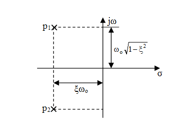
Figure 4 Complex conjugate poles.

Current controller

In order to apply the three analytical methods in the determination of the current controller parameters, a design example is taken into consideration. The LCL filter-based active rectifier has the following components: Lc=L=17.7mH, Lg=5.7mH, and Cf=3.45μF with a resonance frequency around 1.30kHz. In addition, Rc=Rg=0.1Ω is assumed in this paper. The filter has been designed to reduce the switching current ripple to less than 1% of the rated current. The system parameters considered for calculating the components for the filter are shown in (Table 1).11

Grid Voltage (V)

230

Output Power of the Converter (kVA)

1.5

DC-link Voltage (V)

550

DC-link capacitor (mF)

2.4

Grid Frequency (Hz)

50

Table 1 Parameters for calculating the filter components

The d and q control loops have the same dynamics, so the same tuning of the PI parameters is adopted for the two current control axes. The voltage feed forward and the decoupling between the d and q axes in the current control loop of Figure 3 are neglected in the analysis for the generation of the controller parameters as they are considered as disturbances. Employing a more general PI controller transfer function as:

C c (p)= k PC p+ k IC p MathType@MTEF@5@5@+= feaagKart1ev2aaatCvAUfeBSjuyZL2yd9gzLbvyNv2CaerbuLwBLn hiov2DGi1BTfMBaeXatLxBI9gBaerbd9wDYLwzYbItLDharqqtubsr 4rNCHbGeaGqiVu0Je9sqqrpepC0xbbL8F4rqqrFfpeea0xe9Lq=Jc9 vqaqpepm0xbba9pwe9Q8fs0=yqaqpepae9pg0FirpepeKkFr0xfr=x fr=xb9adbaqaaeGaciGaaiaabeqaamaabaabaaGcbaGaam4qamaaBa aaleaacaWGJbaabeaakiaacIcacaWGWbGaaiykaiabg2da9maalaaa baGaam4AamaaBaaaleaacaWGqbGaam4qaaqabaGccaWGWbGaey4kaS Iaam4AamaaBaaaleaacaWGjbGaam4qaaqabaaakeaacaWGWbaaaaaa @438B@ (27)

and the plant model in (19), the open loop Goc(p) and closed loop Gclc(p) transfer functions are as follows:

G oc (p)= k c k PC p+ k c k IC p(p L T + R T ) MathType@MTEF@5@5@+= feaagKart1ev2aaatCvAUfeBSjuyZL2yd9gzLbvyNv2CaerbuLwBLn hiov2DGi1BTfMBaeXatLxBI9gBaerbd9wDYLwzYbItLDharqqtubsr 4rNCHbGeaGqiVu0Je9sqqrpepC0xbbL8F4rqqrFfpeea0xe9Lq=Jc9 vqaqpepm0xbba9pwe9Q8fs0=yqaqpepae9pg0FirpepeKkFr0xfr=x fr=xb9adbaqaaeGaciGaaiaabeqaamaabaabaaGcbaGaam4ramaaBa aaleaacaWGVbGaam4yaaqabaGccaGGOaGaamiCaiaacMcacqGH9aqp daWcaaqaaiaadUgadaWgaaWcbaGaam4yaaqabaGccaWGRbWaaSbaaS qaaiaadcfacaWGdbaabeaakiaadchacqGHRaWkcaWGRbWaaSbaaSqa aiaadogaaeqaaOGaam4AamaaBaaaleaacaWGjbGaam4qaaqabaaake aacaWGWbGaaiikaiaadchacaWGmbWaaSbaaSqaaiaadsfaaeqaaOGa ey4kaSIaamOuamaaBaaaleaacaWGubaabeaakiaacMcaaaaaaa@4F95@ (28)

G clc (p)= 1 L T ( k c k PC p+ k c k IC ) p 2 + ( R T + k c k PC ) L T p+ k c k IC L T MathType@MTEF@5@5@+= feaagKart1ev2aaatCvAUfeBSjuyZL2yd9gzLbvyNv2CaerbuLwBLn hiov2DGi1BTfMBaeXatLxBI9gBaerbd9wDYLwzYbItLDharqqtubsr 4rNCHbGeaGqiVu0Je9sqqrpepC0xbbL8F4rqqrFfpeea0xe9Lq=Jc9 vqaqpepm0xbba9pwe9Q8fs0=yqaqpepae9pg0FirpepeKkFr0xfr=x fr=xb9adbaqaaeGaciGaaiaabeqaamaabaabaaGcbaGaam4ramaaBa aaleaacaWGJbGaamiBaiaadogaaeqaaOGaaiikaiaadchacaGGPaGa eyypa0ZaaSaaaeaadaWcaaqaaiaaigdaaeaacaWGmbWaaSbaaSqaai aadsfaaeqaaaaakiaacIcacaWGRbWaaSbaaSqaaiaadogaaeqaaOGa am4AamaaBaaaleaacaWGqbGaam4qaaqabaGccaWGWbGaey4kaSIaam 4AamaaBaaaleaacaWGJbaabeaakiaadUgadaWgaaWcbaGaamysaiaa doeaaeqaaOGaaiykaaqaaiaadchadaahaaWcbeqaaiaaikdaaaGccq GHRaWkdaWcaaqaaiaacIcacaWGsbWaaSbaaSqaaiaadsfaaeqaaOGa ey4kaSIaam4AamaaBaaaleaacaWGJbaabeaakiaadUgadaWgaaWcba GaamiuaiaadoeaaeqaaOGaaiykaaqaaiaadYeadaWgaaWcbaGaamiv aaqabaaaaOGaamiCaiabgUcaRmaalaaabaGaam4AamaaBaaaleaaca WGJbaabeaakiaadUgadaWgaaWcbaGaamysaiaadoeaaeqaaaGcbaGa amitamaaBaaaleaacaWGubaabeaaaaaaaaaa@62C6@ (29)

Calculation of the closed-loop poles involves solving characteristic equation of the control system:

p 2 + ( R T + k c k PC )p L T + k c k IC L T =0 MathType@MTEF@5@5@+= feaagKart1ev2aaatCvAUfeBSjuyZL2yd9gzLbvyNv2CaerbuLwBLn hiov2DGi1BTfMBaeXatLxBI9gBaerbd9wDYLwzYbItLDharqqtubsr 4rNCHbGeaGqiVu0Je9sqqrpepC0xbbL8F4rqqrFfpeea0xe9Lq=Jc9 vqaqpepm0xbba9pwe9Q8fs0=yqaqpepae9pg0FirpepeKkFr0xfr=x fr=xb9adbaqaaeGaciGaaiaabeqaamaabaabaaGcbaGaamiCamaaCa aaleqabaGaaGOmaaaakiabgUcaRmaalaaabaGaaiikaiaadkfadaWg aaWcbaGaamivaaqabaGccqGHRaWkcaWGRbWaaSbaaSqaaiaadogaae qaaOGaam4AamaaBaaaleaacaWGqbGaam4qaaqabaGccaGGPaGaamiC aaqaaiaadYeadaWgaaWcbaGaamivaaqabaaaaOGaey4kaSYaaSaaae aacaWGRbWaaSbaaSqaaiaadogaaeqaaOGaam4AamaaBaaaleaacaWG jbGaam4qaaqabaaakeaacaWGmbWaaSbaaSqaaiaadsfaaeqaaaaaki abg2da9iaaicdaaaa@4DF3@ (30)

Knowing that a 2nd order system is characterized by the characteristic equation:

p 2 +2ξ ω o p+ ω o 2 =0 MathType@MTEF@5@5@+= feaagKart1ev2aaatCvAUfeBSjuyZL2yd9gzLbvyNv2CaerbuLwBLn hiov2DGi1BTfMBaeXatLxBI9gBaerbd9wDYLwzYbItLDharqqtubsr 4rNCHbGeaGqiVu0Je9sqqrpepC0xbbL8F4rqqrFfpeea0xe9Lq=Jc9 vqaqpepm0xbba9pwe9Q8fs0=yqaqpepae9pg0FirpepeKkFr0xfr=x fr=xb9adbaqaaeGaciGaaiaabeqaamaabaabaaGcbaGaamiCamaaCa aaleqabaGaaGOmaaaakiabgUcaRiaaikdacqaH+oaEcqaHjpWDdaWg aaWcbaGaam4BaaqabaGccaWGWbGaey4kaSIaeqyYdC3aa0baaSqaai aad+gaaeaacaaIYaaaaOGaeyypa0JaaGimaaaa@4581@ (31)

where ξ and ωo correspond to the damping ratio and the natural frequency of the system oscillation, respectively. The gains kpc and kic can be obtained by equating (30) and (31), so that:

ω o 2 = k c k IC L T k IC = L T ω o 2 / k c MathType@MTEF@5@5@+= feaagKart1ev2aaatCvAUfeBSjuyZL2yd9gzLbvyNv2CaerbuLwBLn hiov2DGi1BTfMBaeXatLxBI9gBaerbd9wDYLwzYbItLDharqqtubsr 4rNCHbGeaGqiVu0Je9sqqrpepC0xbbL8F4rqqrFfpeea0xe9Lq=Jc9 vqaqpepm0xbba9pwe9Q8fs0=yqaqpepae9pg0FirpepeKkFr0xfr=x fr=xb9adbaqaaeGaciGaaiaabeqaamaabaabaaGcbaGaeqyYdC3aa0 baaSqaaiaad+gaaeaacaaIYaaaaOGaeyypa0ZaaSaaaeaacaWGRbWa aSbaaSqaaiaadogaaeqaaOGaam4AamaaBaaaleaacaWGjbGaam4qaa qabaaakeaacaWGmbWaaSbaaSqaaiaadsfaaeqaaaaakiabgkDiElaa dUgadaWgaaWcbaGaamysaiaadoeaaeqaaOGaeyypa0JaamitamaaBa aaleaacaWGubaabeaakiabeM8a3naaDaaaleaacaWGVbaabaGaaGOm aaaakiaac+cacaWGRbWaaSbaaSqaaiaadogaaeqaaaaa@4FD4@ (32)

and

2ξ ω o = R T + k c k PC L T k PC =(2ξ ω o L T R T )/ k c MathType@MTEF@5@5@+= feaagKart1ev2aaatCvAUfeBSjuyZL2yd9gzLbvyNv2CaerbuLwBLn hiov2DGi1BTfMBaeXatLxBI9gBaerbd9wDYLwzYbItLDharqqtubsr 4rNCHbGeaGqiVu0Je9sqqrpepC0xbbL8F4rqqrFfpeea0xe9Lq=Jc9 vqaqpepm0xbba9pwe9Q8fs0=yqaqpepae9pg0FirpepeKkFr0xfr=x fr=xb9adbaqaaeGaciGaaiaabeqaamaabaabaaGceaqabeaacaaIYa GaeqOVdGNaeqyYdC3aaSbaaSqaaiaad+gaaeqaaOGaeyypa0ZaaSaa aeaacaWGsbWaaSbaaSqaaiaadsfaaeqaaOGaey4kaSIaam4AamaaBa aaleaacaWGJbaabeaakiaadUgadaWgaaWcbaGaamiuaiaadoeaaeqa aaGcbaGaamitamaaBaaaleaacaWGubaabeaaaaaakeaacqGHshI3ca WGRbWaaSbaaSqaaiaadcfacaWGdbaabeaakiabg2da9iaacIcacaaI YaGaeqOVdGNaeqyYdC3aaSbaaSqaaiaad+gaaeqaaOGaamitamaaBa aaleaacaWGubaabeaakiabgkHiTiaadkfadaWgaaWcbaGaamivaaqa baGccaGGPaGaai4laiaadUgadaWgaaWcbaGaam4yaaqabaaaaaa@5A61@ (33)

The grid-side converter constant is obtained by assuming a unit value for the Vtri, 0.75 for m1, and substituting the DC-link voltage value in Table 1. The natural frequency of the system oscillation and the damping ratio may be established by selecting the settling time ts and maximum overshoot Mp. In this paper, ts≤5ms and Mp≤4.6% are selected. M p = e πξ 1 ξ 2 =0.046 MathType@MTEF@5@5@+= feaagKart1ev2aaatCvAUfeBSjuyZL2yd9gzLbvyNv2CaerbuLwBLn hiov2DGi1BTfMBaeXatLxBI9gBaerbd9wDYLwzYbItLDharqqtubsr 4rNCHbGeaGqiVu0Je9sqqrpepC0xbbL8F4rqqrFfpeea0xe9Lq=Jc9 vqaqpepm0xbba9pwe9Q8fs0=yqaqpepae9pg0FirpepeKkFr0xfr=x fr=xb9adbaqaaeGaciGaaiaabeqaamaabaabaaGcbaGaamytamaaBa aaleaacaWGWbaabeaakiabg2da9iaadwgadaahaaWcbeqaaiabgkHi TmaalaaabaGaeqiWdaNaeqOVdGhabaWaaOaaaeaacaaIXaGaeyOeI0 IaeqOVdG3aaWbaaWqabeaacaaIYaaaaaqabaaaaaaakiabg2da9iaa icdacaGGUaGaaGimaiaaisdacaaI2aaaaa@47A6@ corresponds to ξ=0.7. From t s = 4 ξ ω o =0.005s, MathType@MTEF@5@5@+= feaagKart1ev2aaatCvAUfeBSjuyZL2yd9gzLbvyNv2CaerbuLwBLn hiov2DGi1BTfMBaeXatLxBI9gBaerbd9wDYLwzYbItLDharqqtubsr 4rNCHbGeaGqiVu0Je9sqqrpepC0xbbL8F4rqqrFfpeea0xe9Lq=Jc9 vqaqpepm0xbba9pwe9Q8fs0=yqaqpepae9pg0FirpepeKkFr0xfr=x fr=xb9adbaqaaeGaciGaaiaabeqaamaabaabaaGcbaGaamiDamaaBa aaleaacaWGZbaabeaakiabg2da9maalaaabaGaaGinaaqaaiabe67a 4jabeM8a3naaBaaaleaacaWGVbaabeaaaaGccqGH9aqpcaaIWaGaai OlaiaaicdacaaIWaGaaGynaiaadohacaGGSaaaaa@44F8@ ωo is obtained as 1142.86 rad/s. Substituting ωo into (32) and ωo and ξ into (33), the controller parameters are obtained.

DC-link voltage controller

The PI controller transfer function for the DC-link voltage control is given as:

C v (p)= k PV p+ k IV p MathType@MTEF@5@5@+= feaagKart1ev2aaatCvAUfeBSjuyZL2yd9gzLbvyNv2CaerbuLwBLn hiov2DGi1BTfMBaeXatLxBI9gBaerbd9wDYLwzYbItLDharqqtubsr 4rNCHbGeaGqiVu0Je9sqqrpepC0xbbL8F4rqqrFfpeea0xe9Lq=Jc9 vqaqpepm0xbba9pwe9Q8fs0=yqaqpepae9pg0FirpepeKkFr0xfr=x fr=xb9adbaqaaeGaciGaaiaabeqaamaabaabaaGcbaGaam4qamaaBa aaleaacaWG2baabeaakiaacIcacaWGWbGaaiykaiabg2da9maalaaa baGaam4AamaaBaaaleaacaWGqbGaamOvaaqabaGccaWGWbGaey4kaS Iaam4AamaaBaaaleaacaWGjbGaamOvaaqabaaakeaacaWGWbaaaaaa @43C4@ (34)

The open loop Gov(p) and closed loop Gclv(p) transfer functions are as follows:

G ov (p)= k v k PV p+ k v k IV p(pC) MathType@MTEF@5@5@+= feaagKart1ev2aaatCvAUfeBSjuyZL2yd9gzLbvyNv2CaerbuLwBLn hiov2DGi1BTfMBaeXatLxBI9gBaerbd9wDYLwzYbItLDharqqtubsr 4rNCHbGeaGqiVu0Je9sqqrpepC0xbbL8F4rqqrFfpeea0xe9Lq=Jc9 vqaqpepm0xbba9pwe9Q8fs0=yqaqpepae9pg0FirpepeKkFr0xfr=x fr=xb9adbaqaaeGaciGaaiaabeqaamaabaabaaGcbaGaam4ramaaBa aaleaacaWGVbGaamODaaqabaGccaGGOaGaamiCaiaacMcacqGH9aqp daWcaaqaaiaadUgadaWgaaWcbaGaamODaaqabaGccaWGRbWaaSbaaS qaaiaadcfacaWGwbaabeaakiaadchacqGHRaWkcaWGRbWaaSbaaSqa aiaadAhaaeqaaOGaam4AamaaBaaaleaacaWGjbGaamOvaaqabaaake aacaWGWbGaaiikaiaadchacaWGdbGaaiykaaaaaaa@4C14@ (35)

G clv (p)= 1 C ( k v k PV p+ k v k IV ) p 2 + k v k PV p C + k v k IV C MathType@MTEF@5@5@+= feaagKart1ev2aaatCvAUfeBSjuyZL2yd9gzLbvyNv2CaerbuLwBLn hiov2DGi1BTfMBaeXatLxBI9gBaerbd9wDYLwzYbItLDharqqtubsr 4rNCHbGeaGqiVu0Je9sqqrpepC0xbbL8F4rqqrFfpeea0xe9Lq=Jc9 vqaqpepm0xbba9pwe9Q8fs0=yqaqpepae9pg0FirpepeKkFr0xfr=x fr=xb9adbaqaaeGaciGaaiaabeqaamaabaabaaGcbaGaam4ramaaBa aaleaacaWGJbGaamiBaiaadAhaaeqaaOGaaiikaiaadchacaGGPaGa eyypa0ZaaSaaaeaadaWcaaqaaiaaigdaaeaacaWGdbaaaiaacIcaca WGRbWaaSbaaSqaaiaadAhaaeqaaOGaam4AamaaBaaaleaacaWGqbGa amOvaaqabaGccaWGWbGaey4kaSIaam4AamaaBaaaleaacaWG2baabe aakiaadUgadaWgaaWcbaGaamysaiaadAfaaeqaaOGaaiykaaqaaiaa dchadaahaaWcbeqaaiaaikdaaaGccqGHRaWkdaWcaaqaaiaadUgada WgaaWcbaGaamODaaqabaGccaWGRbWaaSbaaSqaaiaadcfacaWGwbaa beaakiaadchaaeaacaWGdbaaaiabgUcaRmaalaaabaGaam4AamaaBa aaleaacaWG2baabeaakiaadUgadaWgaaWcbaGaamysaiaadAfaaeqa aaGcbaGaam4qaaaaaaaaaa@5C12@ (36)

Comparing the denominator of (36) with (31) yields:

k IV = ω o 2 C/ k v MathType@MTEF@5@5@+= feaagKart1ev2aaatCvAUfeBSjuyZL2yd9gzLbvyNv2CaerbuLwBLn hiov2DGi1BTfMBaeXatLxBI9gBaerbd9wDYLwzYbItLDharqqtubsr 4rNCHbGeaGqiVu0Je9sqqrpepC0xbbL8F4rqqrFfpeea0xe9Lq=Jc9 vqaqpepm0xbba9pwe9Q8fs0=yqaqpepae9pg0FirpepeKkFr0xfr=x fr=xb9adbaqaaeGaciGaaiaabeqaamaabaabaaGcbaGaam4AamaaBa aaleaacaWGjbGaamOvaaqabaGccqGH9aqpcqaHjpWDdaqhaaWcbaGa am4BaaqaaiaaikdaaaGccaWGdbGaai4laiaadUgadaWgaaWcbaGaam ODaaqabaaaaa@4111@ (37)

k PV =2ξ ω o C/ k v MathType@MTEF@5@5@+= feaagKart1ev2aaatCvAUfeBSjuyZL2yd9gzLbvyNv2CaerbuLwBLn hiov2DGi1BTfMBaeXatLxBI9gBaerbd9wDYLwzYbItLDharqqtubsr 4rNCHbGeaGqiVu0Je9sqqrpepC0xbbL8F4rqqrFfpeea0xe9Lq=Jc9 vqaqpepm0xbba9pwe9Q8fs0=yqaqpepae9pg0FirpepeKkFr0xfr=x fr=xb9adbaqaaeGaciGaaiaabeqaamaabaabaaGcbaGaam4AamaaBa aaleaacaWGqbGaamOvaaqabaGccqGH9aqpcaaIYaGaeqOVdGNaeqyY dC3aaSbaaSqaaiaad+gaaeqaaOGaam4qaiaac+cacaWGRbWaaSbaaS qaaiaadAhaaeqaaaaa@42DA@ (38)

Substituting ωo and ωo and ξ obtained previously into (37) and into (38) respectively, the controller parameters are obtained.

Butterworth polynomial method

The Butterworth polynomial method of controller parameter tuning like the pole-zero placement method aims at optimizing the closed-loop eigenvalue locations. In this case the eigenvalues are located uniformly in the left-half s-plane on a circle with bandwidth frequency of the controller denoted in this paper by αo as radius, with its center at the origin,13 as shown in Figure 5. The PI parameters are determined through comparing the coefficients of the Butterworth polynomial with the denominators of the corresponding transfer functions as in pole-zero placement method. The Butterworth polynomial for a transfer function with a second order denominator is given as:

p 2 + 2 p α o + α o 2 =0 MathType@MTEF@5@5@+= feaagKart1ev2aaatCvAUfeBSjuyZL2yd9gzLbvyNv2CaerbuLwBLn hiov2DGi1BTfMBaeXatLxBI9gBaerbd9wDYLwzYbItLDharqqtubsr 4rNCHbGeaGqiVu0Je9sqqrpepC0xbbL8F4rqqrFfpeea0xe9Lq=Jc9 vqaqpepm0xbba9pwe9Q8fs0=yqaqpepae9pg0FirpepeKkFr0xfr=x fr=xb9adbaqaaeGaciGaaiaabeqaamaabaabaaGcbaGaamiCamaaCa aaleqabaGaaGOmaaaakiabgUcaRmaakaaabaGaaGOmaaWcbeaakiaa dchacqaHXoqydaWgaaWcbaGaam4BaaqabaGccqGHRaWkcqaHXoqyda qhaaWcbaGaam4BaaqaaiaaikdaaaGccqGH9aqpcaaIWaaaaa@4387@ (39)

Unlike in the pole-zero placement method, where the settling time ts, and the maximum overshoot Mp must first be specified in order to calculate the natural frequency of the system oscillation and the damping ratio prior to obtaining the controller parameters, the Butterworth polynomial method and the IMC method are both concerned with selection of only the bandwidth frequency of the control loop. The method of selecting the bandwidth frequency is explained in the next section.
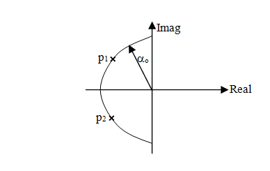
Figure 5 Poles location for 2nd order Butterworth polynomial.

Current controller

To design the inner-loop current controllers, the relation between the d-q components of voltages and currents is first established from (17) and (18) as:

v d = R T i d + L T p i d - ω e L T i q + k c m 1d v DC MathType@MTEF@5@5@+= feaagKart1ev2aaatCvAUfeBSjuyZL2yd9gzLbvyNv2CaerbuLwBLn hiov2DGi1BTfMBaeXatLxBI9gBaerbd9wDYLwzYbItLDharqqtubsr 4rNCHbGeaGqiVu0Je9sqqrpepC0xbbL8F4rqqrFfpeea0xe9Lq=Jc9 vqaqpepm0xbba9pwe9Q8fs0=yqaqpepae9pg0FirpepeKkFr0xfr=x fr=xb9adbaqaaeGaciGaaiaabeqaamaabaabaaGcbaGaamODamaaBa aaleaacaWGKbaabeaakiabg2da9iaadkfadaWgaaWcbaGaamivaaqa baGccaWGPbWaaSbaaSqaaiaadsgaaeqaaOGaey4kaSIaamitamaaBa aaleaacaWGubaabeaakiaadchacaWGPbWaaSbaaSqaaiaadsgaaeqa aGqaaOGaa8xlaiabeM8a3naaBaaaleaacaWGLbaabeaakiaadYeada WgaaWcbaGaamivaaqabaGccaWGPbWaaSbaaSqaaiaadghaaeqaaOGa ey4kaSIaam4AamaaBaaaleaacaWGJbaabeaakiaad2gadaWgaaWcba GaaGymaiaadsgaaeqaaOGaamODamaaBaaaleaacaWGebGaam4qaaqa baaaaa@52DF@ (40)

v q = R T i q + L T p i q + ω e L T i d + m q1 v DC MathType@MTEF@5@5@+= feaagKart1ev2aaatCvAUfeBSjuyZL2yd9gzLbvyNv2CaerbuLwBLn hiov2DGi1BTfMBaeXatLxBI9gBaerbd9wDYLwzYbItLDharqqtubsr 4rNCHbGeaGqiVu0Je9sqqrpepC0xbbL8F4rqqrFfpeea0xe9Lq=Jc9 vqaqpepm0xbba9pwe9Q8fs0=yqaqpepae9pg0FirpepeKkFr0xfr=x fr=xb9adbaqaaeGaciGaaiaabeqaamaabaabaaGcbaGaamODamaaBa aaleaacaWGXbaabeaakiabg2da9iaadkfadaWgaaWcbaGaamivaaqa baGccaWGPbWaaSbaaSqaaiaadghaaeqaaOGaey4kaSIaamitamaaBa aaleaacaWGubaabeaakiaadchacaWGPbWaaSbaaSqaaiaadghaaeqa aOGaey4kaSIaeqyYdC3aaSbaaSqaaiaadwgaaeqaaOGaamitamaaBa aaleaacaWGubaabeaakiaadMgadaWgaaWcbaGaamizaaqabaGccqGH RaWkcaWGTbWaaSbaaSqaaiaadghacaaIXaaabeaakiaadAhadaWgaa WcbaGaamiraiaadoeaaeqaaaaa@5123@ (41)

Equations (40) and (41) are coupled and nonlinear. In order to apply the linear PI controller, the nonlinear equations are linearized by moving the nonlinear parts of the two equations to one side to have:

R T i d + L T p i d = v d + ω e L T i q k c m 1d v DC MathType@MTEF@5@5@+= feaagKart1ev2aaatCvAUfeBSjuyZL2yd9gzLbvyNv2CaerbuLwBLn hiov2DGi1BTfMBaeXatLxBI9gBaerbd9wDYLwzYbItLDharqqtubsr 4rNCHbGeaGqiVu0Je9sqqrpepC0xbbL8F4rqqrFfpeea0xe9Lq=Jc9 vqaqpepm0xbba9pwe9Q8fs0=yqaqpepae9pg0FirpepeKkFr0xfr=x fr=xb9adbaqaaeGaciGaaiaabeqaamaabaabaaGcbaGaamOuamaaBa aaleaacaWGubaabeaakiaadMgadaWgaaWcbaGaamizaaqabaGccqGH RaWkcaWGmbWaaSbaaSqaaiaadsfaaeqaaOGaamiCaiaadMgadaWgaa WcbaGaamizaaqabaGccqGH9aqpcaWG2bWaaSbaaSqaaiaadsgaaeqa aOGaey4kaSIaeqyYdC3aaSbaaSqaaiaadwgaaeqaaOGaamitamaaBa aaleaacaWGubaabeaakiaadMgadaWgaaWcbaGaamyCaaqabaGccqGH sislcaWGRbWaaSbaaSqaaiaadogaaeqaaOGaamyBamaaBaaaleaaca aIXaGaamizaaqabaGccaWG2bWaaSbaaSqaaiaadseacaWGdbaabeaa aaa@5315@ (42)

R T i q + L T p i q = v q ω e L T i d m q1 v DC MathType@MTEF@5@5@+= feaagKart1ev2aaatCvAUfeBSjuyZL2yd9gzLbvyNv2CaerbuLwBLn hiov2DGi1BTfMBaeXatLxBI9gBaerbd9wDYLwzYbItLDharqqtubsr 4rNCHbGeaGqiVu0Je9sqqrpepC0xbbL8F4rqqrFfpeea0xe9Lq=Jc9 vqaqpepm0xbba9pwe9Q8fs0=yqaqpepae9pg0FirpepeKkFr0xfr=x fr=xb9adbaqaaeGaciGaaiaabeqaamaabaabaaGcbaGaamOuamaaBa aaleaacaWGubaabeaakiaadMgadaWgaaWcbaGaamyCaaqabaGccqGH RaWkcaWGmbWaaSbaaSqaaiaadsfaaeqaaOGaamiCaiaadMgadaWgaa WcbaGaamyCaaqabaGccqGH9aqpcaWG2bWaaSbaaSqaaiaadghaaeqa aOGaeyOeI0IaeqyYdC3aaSbaaSqaaiaadwgaaeqaaOGaamitamaaBa aaleaacaWGubaabeaakiaadMgadaWgaaWcbaGaamizaaqabaGccqGH sislcaWGTbWaaSbaaSqaaiaadghacaaIXaaabeaakiaadAhadaWgaa WcbaGaamiraiaadoeaaeqaaaaa@5139@ (43)

From (42) and (43), the current control loop equations are obtained as:

R T i d + L T p i d =( R T +p L T ) i d = k C ( i d * i d ) MathType@MTEF@5@5@+= feaagKart1ev2aaatCvAUfeBSjuyZL2yd9gzLbvyNv2CaerbuLwBLn hiov2DGi1BTfMBaeXatLxBI9gBaerbd9wDYLwzYbItLDharqqtubsr 4rNCHbGeaGqiVu0Je9sqqrpepC0xbbL8F4rqqrFfpeea0xe9Lq=Jc9 vqaqpepm0xbba9pwe9Q8fs0=yqaqpepae9pg0FirpepeKkFr0xfr=x fr=xb9adbaqaaeGaciGaaiaabeqaamaabaabaaGcbaGaamOuamaaBa aaleaacaWGubaabeaakiaadMgadaWgaaWcbaGaamizaaqabaGccqGH RaWkcaWGmbWaaSbaaSqaaiaadsfaaeqaaOGaamiCaiaadMgadaWgaa WcbaGaamizaaqabaGccqGH9aqpcaGGOaGaamOuamaaBaaaleaacaWG ubaabeaakiabgUcaRiaadchacaWGmbWaaSbaaSqaaiaadsfaaeqaaO GaaiykaiaadMgadaWgaaWcbaGaamizaaqabaGccqGH9aqpcaWGRbWa aSbaaSqaaiaadoeaaeqaaOGaaiikaiaadMgadaqhaaWcbaGaamizaa qaaiaacQcaaaGccqGHsislcaWGPbWaaSbaaSqaaiaadsgaaeqaaOGa aiykaaaa@53B9@ (44)

R T i q + L T p i q =( R T +p L T ) i q = k C ( i q * i q ) MathType@MTEF@5@5@+= feaagKart1ev2aaatCvAUfeBSjuyZL2yd9gzLbvyNv2CaerbuLwBLn hiov2DGi1BTfMBaeXatLxBI9gBaerbd9wDYLwzYbItLDharqqtubsr 4rNCHbGeaGqiVu0Je9sqqrpepC0xbbL8F4rqqrFfpeea0xe9Lq=Jc9 vqaqpepm0xbba9pwe9Q8fs0=yqaqpepae9pg0FirpepeKkFr0xfr=x fr=xb9adbaqaaeGaciGaaiaabeqaamaabaabaaGcbaGaamOuamaaBa aaleaacaWGubaabeaakiaadMgadaWgaaWcbaGaamyCaaqabaGccqGH RaWkcaWGmbWaaSbaaSqaaiaadsfaaeqaaOGaamiCaiaadMgadaWgaa WcbaGaamyCaaqabaGccqGH9aqpcaGGOaGaamOuamaaBaaaleaacaWG ubaabeaakiabgUcaRiaadchacaWGmbWaaSbaaSqaaiaadsfaaeqaaO GaaiykaiaadMgadaWgaaWcbaGaamyCaaqabaGccqGH9aqpcaWGRbWa aSbaaSqaaiaadoeaaeqaaOGaaiikaiaadMgadaqhaaWcbaGaamyCaa qaaiaacQcaaaGccqGHsislcaWGPbWaaSbaaSqaaiaadghaaeqaaOGa aiykaaaa@53FA@ (45)

where k C =( k PC + k IC p ) MathType@MTEF@5@5@+= feaagKart1ev2aaatCvAUfeBSjuyZL2yd9gzLbvyNv2CaerbuLwBLn hiov2DGi1BTfMBaeXatLxBI9gBaerbd9wDYLwzYbItLDharqqtubsr 4rNCHbGeaGqiVu0Je9sqqrpepC0xbbL8F4rqqrFfpeea0xe9Lq=Jc9 vqaqpepm0xbba9pwe9Q8fs0=yqaqpepae9pg0FirpepeKkFr0xfr=x fr=xb9adbaqaaeGaciGaaiaabeqaamaabaabaaGcbaGaam4AamaaBa aaleaacaWGdbaabeaakiabg2da9maabmaabaGaam4AamaaBaaaleaa caWGqbGaam4qaaqabaGccqGHRaWkdaWcaaqaaiaadUgadaWgaaWcba GaamysaiaadoeaaeqaaaGcbaGaamiCaaaaaiaawIcacaGLPaaaaaa@41D9@ is the current controller. Again, the d and q control loops have the same dynamics, so the same tuning of the PI parameters is adopted for the two current control axes. Thus (44) and (45) may be expanded in one to have:

( R T +p L T ) i dq =( k PC + k IC p ) i dq * ( k PC + K IC p ) i dq MathType@MTEF@5@5@+= feaagKart1ev2aaatCvAUfeBSjuyZL2yd9gzLbvyNv2CaerbuLwBLn hiov2DGi1BTfMBaeXatLxBI9gBaerbd9wDYLwzYbItLDharqqtubsr 4rNCHbGeaGqiVu0Je9sqqrpepC0xbbL8F4rqqrFfpeea0xe9Lq=Jc9 vqaqpepm0xbba9pwe9Q8fs0=yqaqpepae9pg0FirpepeKkFr0xfr=x fr=xb9adbaqaaeGaciGaaiaabeqaamaabaabaaGcbaGaaiikaiaadk fadaWgaaWcbaGaamivaaqabaGccqGHRaWkcaWGWbGaamitamaaBaaa leaacaWGubaabeaakiaacMcacaWGPbWaaSbaaSqaaiaadsgacaWGXb aabeaakiabg2da9maabmaabaGaam4AamaaBaaaleaacaWGqbGaam4q aaqabaGccqGHRaWkdaWcaaqaaiaadUgadaWgaaWcbaGaamysaiaado eaaeqaaaGcbaGaamiCaaaaaiaawIcacaGLPaaacaWGPbWaa0baaSqa aiaadsgacaWGXbaabaGaaiOkaaaakiabgkHiTmaabmaabaGaam4Aam aaBaaaleaacaWGqbGaam4qaaqabaGccqGHRaWkdaWcaaqaaiaadUea daWgaaWcbaGaamysaiaadoeaaeqaaaGcbaGaamiCaaaaaiaawIcaca GLPaaacaWGPbWaaSbaaSqaaiaadsgacaWGXbaabeaaaaa@5A4B@ (46)

from which we obtain:

i d i d * = i q i q * = 1 L T ( p k PC + k IC ) p 2 +p 1 L T ( R T + k PC )+ 1 L T k IC MathType@MTEF@5@5@+= feaagKart1ev2aaatCvAUfeBSjuyZL2yd9gzLbvyNv2CaerbuLwBLn hiov2DGi1BTfMBaeXatLxBI9gBaerbd9wDYLwzYbItLDharqqtubsr 4rNCHbGeaGqiVu0Je9sqqrpepC0xbbL8F4rqqrFfpeea0xe9Lq=Jc9 vqaqpepm0xbba9pwe9Q8fs0=yqaqpepae9pg0FirpepeKkFr0xfr=x fr=xb9adbaqaaeGaciGaaiaabeqaamaabaabaaGcbaWaaSaaaeaaca WGPbWaaSbaaSqaaiaadsgaaeqaaaGcbaGaamyAamaaDaaaleaacaWG KbaabaGaaiOkaaaaaaGccqGH9aqpdaWcaaqaaiaadMgadaWgaaWcba GaamyCaaqabaaakeaacaWGPbWaa0baaSqaaiaadghaaeaacaGGQaaa aaaakiabg2da9maalaaabaWaaSaaaeaacaaIXaaabaGaamitamaaBa aaleaacaWGubaabeaaaaGcdaqadaqaaiaadchacaWGRbWaaSbaaSqa aiaadcfacaWGdbaabeaakiabgUcaRiaadUgadaWgaaWcbaGaamysai aadoeaaeqaaaGccaGLOaGaayzkaaaabaGaamiCamaaCaaaleqabaGa aGOmaaaakiabgUcaRiaadchadaWcaaqaaiaaigdaaeaacaWGmbWaaS baaSqaaiaadsfaaeqaaaaakiaacIcacaWGsbWaaSbaaSqaaiaadsfa aeqaaOGaey4kaSIaam4AamaaBaaaleaacaWGqbGaam4qaaqabaGcca GGPaGaey4kaSYaaSaaaeaacaaIXaaabaGaamitamaaBaaaleaacaWG ubaabeaaaaGccaWGRbWaaSbaaSqaaiaadMeacaWGdbaabeaaaaaaaa@60F5@ (47)

Comparing the denominator of (47) with the Butterworth second order polynomial of (39) yields:

k PC = 2 α o L T R T MathType@MTEF@5@5@+= feaagKart1ev2aaatCvAUfeBSjuyZL2yd9gzLbvyNv2CaerbuLwBLn hiov2DGi1BTfMBaeXatLxBI9gBaerbd9wDYLwzYbItLDharqqtubsr 4rNCHbGeaGqiVu0Je9sqqrpepC0xbbL8F4rqqrFfpeea0xe9Lq=Jc9 vqaqpepm0xbba9pwe9Q8fs0=yqaqpepae9pg0FirpepeKkFr0xfr=x fr=xb9adbaqaaeGaciGaaiaabeqaamaabaabaaGcbaGaam4AamaaBa aaleaacaWGqbGaam4qaaqabaGccqGH9aqpdaGcaaqaaiaaikdaaSqa baGccqaHXoqydaWgaaWcbaGaam4BaaqabaGccaWGmbWaaSbaaSqaai aadsfaaeqaaOGaeyOeI0IaamOuamaaBaaaleaacaWGubaabeaaaaa@4212@ (48)

k IC = L T α o 2 MathType@MTEF@5@5@+= feaagKart1ev2aaatCvAUfeBSjuyZL2yd9gzLbvyNv2CaerbuLwBLn hiov2DGi1BTfMBaeXatLxBI9gBaerbd9wDYLwzYbItLDharqqtubsr 4rNCHbGeaGqiVu0Je9sqqrpepC0xbbL8F4rqqrFfpeea0xe9Lq=Jc9 vqaqpepm0xbba9pwe9Q8fs0=yqaqpepae9pg0FirpepeKkFr0xfr=x fr=xb9adbaqaaeGaciGaaiaabeqaamaabaabaaGcbaGaam4AamaaBa aaleaacaWGjbGaam4qaaqabaGccqGH9aqpcaWGmbWaaSbaaSqaaiaa dsfaaeqaaOGaeqySde2aa0baaSqaaiaad+gaaeaacaaIYaaaaaaa@3F14@ (49)

where αo is the bandwidth frequency of the current controller.

DC-link voltage controller

The DC-link voltage dynamics may be given by:

Cp v DC = 3 2 ( m dg i dg + m qg i qg )+ 3 2 ( m d i d + m q i q ) MathType@MTEF@5@5@+= feaagKart1ev2aaatCvAUfeBSjuyZL2yd9gzLbvyNv2CaerbuLwBLn hiov2DGi1BTfMBaeXatLxBI9gBaerbd9wDYLwzYbItLDharqqtubsr 4rNCHbGeaGqiVu0Je9sqqrpepC0xbbL8F4rqqrFfpeea0xe9Lq=Jc9 vqaqpepm0xbba9pwe9Q8fs0=yqaqpepae9pg0FirpepeKkFr0xfr=x fr=xb9adbaqaaeGaciGaaiaabeqaamaabaabaaGcbaGaam4qaiaadc hacaWG2bWaaSbaaSqaaiaadseacaWGdbaabeaakiabg2da9maalaaa baGaaG4maaqaaiaaikdaaaWaaeWaaeaacaWGTbWaaSbaaSqaaiaads gacaWGNbaabeaakiaadMgadaWgaaWcbaGaamizaiaadEgaaeqaaOGa ey4kaSIaamyBamaaBaaaleaacaWGXbGaam4zaaqabaGccaWGPbWaaS baaSqaaiaadghacaWGNbaabeaaaOGaayjkaiaawMcaaiabgUcaRmaa laaabaGaaG4maaqaaiaaikdaaaWaaeWaaeaacaWGTbWaaSbaaSqaai aadsgaaeqaaOGaamyAamaaBaaaleaacaWGKbaabeaakiabgUcaRiaa d2gadaWgaaWcbaGaamyCaaqabaGccaWGPbWaaSbaaSqaaiaadghaae qaaaGccaGLOaGaayzkaaaaaa@58A1@ (50)

where mdg and mqg are the d and q-axis modulation indexes of the GSC and md and mq are the d and q-axis modulation indexes of the second converter not shown, respectively. In order to generate the d-component of the reference current i dg MathType@MTEF@5@5@+= feaagKart1ev2aaatCvAUfeBSjuyZL2yd9gzLbvyNv2CaerbuLwBLn hiov2DGi1BTfMBaeXatLxBI9gBaerbd9wDYLwzYbItLDharqqtubsr 4rNCHbGeaGqiVu0Je9sqqrpepC0xbbL8F4rqqrFfpeea0xe9Lq=Jc9 vqaqpepm0xbba9pwe9Q8fs0=yqaqpepae9pg0FirpepeKkFr0xfr=x fr=xb9adbaqaaeGaciGaaiaabeqaamaabaabaaGcbaGaamyAamaaDa aaleaacaWGKbGaam4zaaqaaiabgEHiQaaaaaa@39D5@ for the inner loop, (50) may be re-written as [13]:

Cp v DC = 3 2 ( m dg i dg + m qg i qg )+ 3 2 ( m d i d + m q i q )= δ V MathType@MTEF@5@5@+= feaagKart1ev2aaatCvAUfeBSjuyZL2yd9gzLbvyNv2CaerbuLwBLn hiov2DGi1BTfMBaeXatLxBI9gBaerbd9wDYLwzYbItLDharqqtubsr 4rNCHbGeaGqiVu0Je9sqqrpepC0xbbL8F4rqqrFfpeea0xe9Lq=Jc9 vqaqpepm0xbba9pwe9Q8fs0=yqaqpepae9pg0FirpepeKkFr0xfr=x fr=xb9adbaqaaeGaciGaaiaabeqaamaabaabaaGcbaGaam4qaiaadc hacaWG2bWaaSbaaSqaaiaadseacaWGdbaabeaakiabg2da9maalaaa baGaaG4maaqaaiaaikdaaaWaaeWaaeaacaWGTbWaaSbaaSqaaiaads gacaWGNbaabeaakiaadMgadaWgaaWcbaGaamizaiaadEgaaeqaaOGa ey4kaSIaamyBamaaBaaaleaacaWGXbGaam4zaaqabaGccaWGPbWaaS baaSqaaiaadghacaWGNbaabeaaaOGaayjkaiaawMcaaiabgUcaRmaa laaabaGaaG4maaqaaiaaikdaaaWaaeWaaeaacaWGTbWaaSbaaSqaai aadsgaaeqaaOGaamyAamaaBaaaleaacaWGKbaabeaakiabgUcaRiaa d2gadaWgaaWcbaGaamyCaaqabaGccaWGPbWaaSbaaSqaaiaadghaae qaaaGccaGLOaGaayzkaaGaeyypa0JaeqiTdq2aaSbaaSqaaiaadAfa aeqaaaaa@5C53@ (51)

Equation (50) may also be re-written as:

Cp v DC = δ V = k V ( v DC * v DC ) MathType@MTEF@5@5@+= feaagKart1ev2aaatCvAUfeBSjuyZL2yd9gzLbvyNv2CaerbuLwBLn hiov2DGi1BTfMBaeXatLxBI9gBaerbd9wDYLwzYbItLDharqqtubsr 4rNCHbGeaGqiVu0Je9sqqrpepC0xbbL8F4rqqrFfpeea0xe9Lq=Jc9 vqaqpepm0xbba9pwe9Q8fs0=yqaqpepae9pg0FirpepeKkFr0xfr=x fr=xb9adbaqaaeGaciGaaiaabeqaamaabaabaaGcbaGaam4qaiaadc hacaWG2bWaaSbaaSqaaiaadseacaWGdbaabeaakiabg2da9iabes7a KnaaBaaaleaacaWGwbaabeaakiabg2da9iaadUgadaWgaaWcbaGaam OvaaqabaGccaGGOaGaamODamaaDaaaleaacaWGebGaam4qaaqaaiaa cQcaaaGccqGHsislcaWG2bWaaSbaaSqaaiaadseacaWGdbaabeaaki aacMcaaaa@49B1@ (52)

where kV is the PI controller for DC-voltage control given as:

k V = k PV + k IV p MathType@MTEF@5@5@+= feaagKart1ev2aaatCvAUfeBSjuyZL2yd9gzLbvyNv2CaerbuLwBLn hiov2DGi1BTfMBaeXatLxBI9gBaerbd9wDYLwzYbItLDharqqtubsr 4rNCHbGeaGqiVu0Je9sqqrpepC0xbbL8F4rqqrFfpeea0xe9Lq=Jc9 vqaqpepm0xbba9pwe9Q8fs0=yqaqpepae9pg0FirpepeKkFr0xfr=x fr=xb9adbaqaaeGaciGaaiaabeqaamaabaabaaGcbaGaam4AamaaBa aaleaacaWGwbaabeaakiabg2da9iaadUgadaWgaaWcbaGaamiuaiaa dAfaaeqaaOGaey4kaSYaaSaaaeaacaWGRbWaaSbaaSqaaiaadMeaca WGwbaabeaaaOqaaiaadchaaaaaaa@4089@ (53)

In an expanded form, (52) will be:

Cp v DC =( k PV + k IV p ) v DC * ( k PV + k IV p ) v DC MathType@MTEF@5@5@+= feaagKart1ev2aaatCvAUfeBSjuyZL2yd9gzLbvyNv2CaerbuLwBLn hiov2DGi1BTfMBaeXatLxBI9gBaerbd9wDYLwzYbItLDharqqtubsr 4rNCHbGeaGqiVu0Je9sqqrpepC0xbbL8F4rqqrFfpeea0xe9Lq=Jc9 vqaqpepm0xbba9pwe9Q8fs0=yqaqpepae9pg0FirpepeKkFr0xfr=x fr=xb9adbaqaaeGaciGaaiaabeqaamaabaabaaGcbaGaam4qaiaadc hacaWG2bWaaSbaaSqaaiaadseacaWGdbaabeaakiabg2da9maabmaa baGaam4AamaaBaaaleaacaWGqbGaamOvaaqabaGccqGHRaWkdaWcaa qaaiaadUgadaWgaaWcbaGaamysaiaadAfaaeqaaaGcbaGaamiCaaaa aiaawIcacaGLPaaacaWG2bWaa0baaSqaaiaadseacaWGdbaabaGaai OkaaaakiabgkHiTmaabmaabaGaam4AamaaBaaaleaacaWGqbGaamOv aaqabaGccqGHRaWkdaWcaaqaaiaadUgadaWgaaWcbaGaamysaiaadA faaeqaaaGcbaGaamiCaaaaaiaawIcacaGLPaaacaWG2bWaaSbaaSqa aiaadseacaWGdbaabeaaaaa@54BB@ (54)

from which:

v DC v DC * = 1 C ( p k PV + k IV ) p 2 +p k PV C + k IV C MathType@MTEF@5@5@+= feaagKart1ev2aaatCvAUfeBSjuyZL2yd9gzLbvyNv2CaerbuLwBLn hiov2DGi1BTfMBaeXatLxBI9gBaerbd9wDYLwzYbItLDharqqtubsr 4rNCHbGeaGqiVu0Je9sqqrpepC0xbbL8F4rqqrFfpeea0xe9Lq=Jc9 vqaqpepm0xbba9pwe9Q8fs0=yqaqpepae9pg0FirpepeKkFr0xfr=x fr=xb9adbaqaaeGaciGaaiaabeqaamaabaabaaGcbaWaaSaaaeaaca WG2bWaaSbaaSqaaiaadseacaWGdbaabeaaaOqaaiaadAhadaqhaaWc baGaamiraiaadoeaaeaacaGGQaaaaaaakiabg2da9maalaaabaWaaS aaaeaacaaIXaaabaGaam4qaaaadaqadaqaaiaadchacaWGRbWaaSba aSqaaiaadcfacaWGwbaabeaakiabgUcaRiaadUgadaWgaaWcbaGaam ysaiaadAfaaeqaaaGccaGLOaGaayzkaaaabaGaamiCamaaCaaaleqa baGaaGOmaaaakiabgUcaRiaadchadaWcaaqaaiaadUgadaWgaaWcba GaamiuaiaadAfaaeqaaaGcbaGaam4qaaaacqGHRaWkdaWcaaqaaiaa dUgadaWgaaWcbaGaamysaiaadAfaaeqaaaGcbaGaam4qaaaaaaaaaa@53DD@ (55)

Comparing the denominator of (55) with Butterworth second order polynomial, the PI controller gains are obtained as:

k PV = 2 α o C MathType@MTEF@5@5@+= feaagKart1ev2aaatCvAUfeBSjuyZL2yd9gzLbvyNv2CaerbuLwBLn hiov2DGi1BTfMBaeXatLxBI9gBaerbd9wDYLwzYbItLDharqqtubsr 4rNCHbGeaGqiVu0Je9sqqrpepC0xbbL8F4rqqrFfpeea0xe9Lq=Jc9 vqaqpepm0xbba9pwe9Q8fs0=yqaqpepae9pg0FirpepeKkFr0xfr=x fr=xb9adbaqaaeGaciGaaiaabeqaamaabaabaaGcbaGaam4AamaaBa aaleaacaWGqbGaamOvaaqabaGccqGH9aqpdaGcaaqaaiaaikdaaSqa baGccqaHXoqydaWgaaWcbaGaam4BaaqabaGccaWGdbaaaa@3E44@ (56)

k IV = α o 2 C MathType@MTEF@5@5@+= feaagKart1ev2aaatCvAUfeBSjuyZL2yd9gzLbvyNv2CaerbuLwBLn hiov2DGi1BTfMBaeXatLxBI9gBaerbd9wDYLwzYbItLDharqqtubsr 4rNCHbGeaGqiVu0Je9sqqrpepC0xbbL8F4rqqrFfpeea0xe9Lq=Jc9 vqaqpepm0xbba9pwe9Q8fs0=yqaqpepae9pg0FirpepeKkFr0xfr=x fr=xb9adbaqaaeGaciGaaiaabeqaamaabaabaaGcbaGaam4AamaaBa aaleaacaWGjbGaamOvaaqabaGccqGH9aqpcqaHXoqydaqhaaWcbaGa am4BaaqaaiaaikdaaaGccaWGdbaaaa@3E19@ (57)

where αo is the bandwidth frequency of the DC-link voltage controller.

Internal model control method

The internal model control (IMC) structure has been a very popular one in process control application, especially as applied to AC machine current and speed controls.14-16 The prime benefit of this structure is the deployment of the model of the plant and the desired closed-loop bandwidth in the determination of the controller parameters (gain and integration time). In this case, the tuning problem, which for a PI controller involves adjustment of two parameters, is reduced to the selection of one parameter only, the desired closed-loop bandwidth α. The idea behind IMC is to augment the error between the process, G(p) and a process model, G ^ (p) MathType@MTEF@5@5@+= feaagKart1ev2aaatCvAUfeBSjuyZL2yd9gzLbvyNv2CaerbuLwBLn hiov2DGi1BTfMBaeXatLxBI9gBaerbd9wDYLwzYbItLDharqqtubsr 4rNCHbGeaGqiVu0Je9sqqrpepC0xbbL8F4rqqrFfpeea0xe9Lq=Jc9 vqaqpepm0xbba9pwe9Q8fs0=yqaqpepae9pg0FirpepeKkFr0xfr=x fr=xb9adbaqaaeGaciGaaiaabeqaamaabaabaaGcbaGabm4rayaaja GaaiikaiaadchacaGGPaaaaa@3920@ by a transfer function C(p); see (Figure 6).
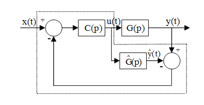
Figure 6 Principle of IMC.

Current controller

The IMC structure uses an internal model G ^ (p) MathType@MTEF@5@5@+= feaagKart1ev2aaatCvAUfeBSjuyZL2yd9gzLbvyNv2CaerbuLwBLn hiov2DGi1BTfMBaeXatLxBI9gBaerbd9wDYLwzYbItLDharqqtubsr 4rNCHbGeaGqiVu0Je9sqqrpepC0xbbL8F4rqqrFfpeea0xe9Lq=Jc9 vqaqpepm0xbba9pwe9Q8fs0=yqaqpepae9pg0FirpepeKkFr0xfr=x fr=xb9adbaqaaeGaciGaaiaabeqaamaabaabaaGcbaGabm4rayaaja GaaiikaiaadchacaGGPaaaaa@3920@ in parallel with the controlled system plant G(p). For an AC machine, u and y could be the stator voltage and current vectors, respectively, while x= [ i d ref , i q ref ] T MathType@MTEF@5@5@+= feaagKart1ev2aaatCvAUfeBSjuyZL2yd9gzLbvyNv2CaerbuLwBLn hiov2DGi1BTfMBaeXatLxBI9gBaerbd9wDYLwzYbItLDharqqtubsr 4rNCHbGeaGqiVu0Je9sqqrpepC0xbbL8F4rqqrFfpeea0xe9Lq=Jc9 vqaqpepm0xbba9pwe9Q8fs0=yqaqpepae9pg0FirpepeKkFr0xfr=x fr=xb9adbaqaaeGaciGaaiaabeqaamaabaabaaGcbaGaamiEaiabg2 da9iaacUfacaWGPbWaa0baaSqaaiaadsgaaeaacaWGYbGaamyzaiaa dAgaaaGccaGGSaGaaGjbVlaadMgadaqhaaWcbaGaamyCaaqaaiaadk hacaWGLbGaamOzaaaakiaac2fadaahaaWcbeqaaiaadsfaaaaaaa@46BD@ is the current set point (reference) vector. The control loop is augmented by a block C(p), the so called IMC controller. G(p), G ^ (p),andC(p) MathType@MTEF@5@5@+= feaagKart1ev2aaatCvAUfeBSjuyZL2yd9gzLbvyNv2CaerbuLwBLn hiov2DGi1BTfMBaeXatLxBI9gBaerbd9wDYLwzYbItLDharqqtubsr 4rNCHbGeaGqiVu0Je9sqqrpepC0xbbL8F4rqqrFfpeea0xe9Lq=Jc9 vqaqpepm0xbba9pwe9Q8fs0=yqaqpepae9pg0FirpepeKkFr0xfr=x fr=xb9adbaqaaeGaciGaaiaabeqaamaabaabaaGcbaGaam4raiaacI cacaWGWbGaaiykaiaacYcacaaMe8UaaGPaVlqadEeagaqcaiaacIca caWGWbGaaiykaiaacYcacaaMe8UaaGPaVlaadggacaWGUbGaamizai aaysW7caWGdbGaaiikaiaadchacaGGPaaaaa@4B2F@ are all transfer function matrices. It should be noted that, if the internal model is perfect, i.e. G ^ (p)=G(p), MathType@MTEF@5@5@+= feaagKart1ev2aaatCvAUfeBSjuyZL2yd9gzLbvyNv2CaerbuLwBLn hiov2DGi1BTfMBaeXatLxBI9gBaerbd9wDYLwzYbItLDharqqtubsr 4rNCHbGeaGqiVu0Je9sqqrpepC0xbbL8F4rqqrFfpeea0xe9Lq=Jc9 vqaqpepm0xbba9pwe9Q8fs0=yqaqpepae9pg0FirpepeKkFr0xfr=x fr=xb9adbaqaaeGaciGaaiaabeqaamaabaabaaGcbaGabm4rayaaja GaaiikaiaadchacaGGPaGaeyypa0JaaGjbVlaadEeacaGGOaGaamiC aiaacMcacaGGSaaaaa@3F7D@ there is no internal feedback loop in Figure 6 and the closed-loop system has the transfer function matrix:

G c (p)=G(p)C(p) MathType@MTEF@5@5@+= feaagKart1ev2aaatCvAUfeBSjuyZL2yd9gzLbvyNv2CaerbuLwBLn hiov2DGi1BTfMBaeXatLxBI9gBaerbd9wDYLwzYbItLDharqqtubsr 4rNCHbGeaGqiVu0Je9sqqrpepC0xbbL8F4rqqrFfpeea0xe9Lq=Jc9 vqaqpepm0xbba9pwe9Q8fs0=yqaqpepae9pg0FirpepeKkFr0xfr=x fr=xb9adbaqaaeGaciGaaiaabeqaamaabaabaaGcbaGaam4ramaaBa aaleaacaWGJbaabeaakiaacIcacaWGWbGaaiykaiabg2da9iaadEea caGGOaGaamiCaiaacMcacaWGdbGaaiikaiaadchacaGGPaaaaa@4164@ (58)

Controller design is a matter of choosing the “right” transfer function C(s). One common way is:17

C(p)= ( α p+α ) n G 1 (p) MathType@MTEF@5@5@+= feaagKart1ev2aaatCvAUfeBSjuyZL2yd9gzLbvyNv2CaerbuLwBLn hiov2DGi1BTfMBaeXatLxBI9gBaerbd9wDYLwzYbItLDharqqtubsr 4rNCHbGeaGqiVu0Je9sqqrpepC0xbbL8F4rqqrFfpeea0xe9Lq=Jc9 vqaqpepm0xbba9pwe9Q8fs0=yqaqpepae9pg0FirpepeKkFr0xfr=x fr=xb9adbaqaaeGaciGaaiaabeqaamaabaabaaGcbaGaam4qaiaacI cacaWGWbGaaiykaiabg2da9maabmaabaWaaSaaaeaacqaHXoqyaeaa caWGWbGaey4kaSIaeqySdegaaaGaayjkaiaawMcaamaaCaaaleqaba GaamOBaaaakiaadEeadaahaaWcbeqaaiabgkHiTiaaigdaaaGccaGG OaGaamiCaiaacMcaaaa@46E3@ (58)

where n is chosen so that C(p) become proper, i.e., the order of the denominator is equal to or greater than that of the numerator. The parameter α is a design parameter, which for n=1, is set to the desired bandwidth of the closed-loop system. For a first-order system, n=1 is sufficient. For the inner-current control, the controller then typically becomes an ordinary PI controller:

C C (p)= α p G C 1 (p)= k PC + k IC p MathType@MTEF@5@5@+= feaagKart1ev2aaatCvAUfeBSjuyZL2yd9gzLbvyNv2CaerbuLwBLn hiov2DGi1BTfMBaeXatLxBI9gBaerbd9wDYLwzYbItLDharqqtubsr 4rNCHbGeaGqiVu0Je9sqqrpepC0xbbL8F4rqqrFfpeea0xe9Lq=Jc9 vqaqpepm0xbba9pwe9Q8fs0=yqaqpepae9pg0FirpepeKkFr0xfr=x fr=xb9adbaqaaeGaciGaaiaabeqaamaabaabaaGcbaGaam4qamaaBa aaleaacaWGdbaabeaakiaacIcacaWGWbGaaiykaiabg2da9maalaaa baGaeqySdegabaGaamiCaaaacaWGhbWaaSbaaSqaaiaadoeaaeqaaO WaaWbaaSqabeaacqGHsislcaaIXaaaaOGaaiikaiaadchacaGGPaGa eyypa0Jaam4AamaaBaaaleaacaWGqbGaam4qaaqabaGccqGHRaWkda WcaaqaaiaadUgadaWgaaWcbaGaamysaiaadoeaaeqaaaGcbaGaamiC aaaaaaa@4C17@ (59)

With GC(p) comprising the product of the grid-side converter constant and the system plant as:

G C (p)= k c p L T + R T MathType@MTEF@5@5@+= feaagKart1ev2aaatCvAUfeBSjuyZL2yd9gzLbvyNv2CaerbuLwBLn hiov2DGi1BTfMBaeXatLxBI9gBaerbd9wDYLwzYbItLDharqqtubsr 4rNCHbGeaGqiVu0Je9sqqrpepC0xbbL8F4rqqrFfpeea0xe9Lq=Jc9 vqaqpepm0xbba9pwe9Q8fs0=yqaqpepae9pg0FirpepeKkFr0xfr=x fr=xb9adbaqaaeGaciGaaiaabeqaamaabaabaaGcbaGaam4ramaaBa aaleaacaWGdbaabeaakiaacIcacaWGWbGaaiykaiabg2da9maalaaa baGaam4AamaaBaaaleaacaWGJbaabeaaaOqaaiaadchacaWGmbWaaS baaSqaaiaadsfaaeqaaOGaey4kaSIaamOuamaaBaaaleaacaWGubaa beaaaaaaaa@42C5@ (60)

the PI controller gains are:

k pC = α L T k c MathType@MTEF@5@5@+= feaagKart1ev2aaatCvAUfeBSjuyZL2yd9gzLbvyNv2CaerbuLwBLn hiov2DGi1BTfMBaeXatLxBI9gBaerbd9wDYLwzYbItLDharqqtubsr 4rNCHbGeaGqiVu0Je9sqqrpepC0xbbL8F4rqqrFfpeea0xe9Lq=Jc9 vqaqpepm0xbba9pwe9Q8fs0=yqaqpepae9pg0FirpepeKkFr0xfr=x fr=xb9adbaqaaeGaciGaaiaabeqaamaabaabaaGcbaGaam4AamaaBa aaleaacaWGWbGaam4qaaqabaGccqGH9aqpdaWcaaqaaiabeg7aHjaa dYeadaWgaaWcbaGaamivaaqabaaakeaacaWGRbWaaSbaaSqaaiaado gaaeqaaaaaaaa@3F72@ ; k iC = α R T k c MathType@MTEF@5@5@+= feaagKart1ev2aaatCvAUfeBSjuyZL2yd9gzLbvyNv2CaerbuLwBLn hiov2DGi1BTfMBaeXatLxBI9gBaerbd9wDYLwzYbItLDharqqtubsr 4rNCHbGeaGqiVu0Je9sqqrpepC0xbbL8F4rqqrFfpeea0xe9Lq=Jc9 vqaqpepm0xbba9pwe9Q8fs0=yqaqpepae9pg0FirpepeKkFr0xfr=x fr=xb9adbaqaaeGaciGaaiaabeqaamaabaabaaGcbaGaam4AamaaBa aaleaacaWGPbGaam4qaaqabaGccqGH9aqpdaWcaaqaaiabeg7aHjaa dkfadaWgaaWcbaGaamivaaqabaaakeaacaWGRbWaaSbaaSqaaiaado gaaeqaaaaaaaa@3F71@ (61)

DC-link voltage controller

For the DC-link voltage control, the PI controller is:

C V (p)= α p G V 1 (p)= k PV + k IV p MathType@MTEF@5@5@+= feaagKart1ev2aaatCvAUfeBSjuyZL2yd9gzLbvyNv2CaerbuLwBLn hiov2DGi1BTfMBaeXatLxBI9gBaerbd9wDYLwzYbItLDharqqtubsr 4rNCHbGeaGqiVu0Je9sqqrpepC0xbbL8F4rqqrFfpeea0xe9Lq=Jc9 vqaqpepm0xbba9pwe9Q8fs0=yqaqpepae9pg0FirpepeKkFr0xfr=x fr=xb9adbaqaaeGaciGaaiaabeqaamaabaabaaGcbaGaam4qamaaBa aaleaacaWGwbaabeaakiaacIcacaWGWbGaaiykaiabg2da9maalaaa baGaeqySdegabaGaamiCaaaacaWGhbWaaSbaaSqaaiaadAfaaeqaaO WaaWbaaSqabeaacqGHsislcaaIXaaaaOGaaiikaiaadchacaGGPaGa eyypa0Jaam4AamaaBaaaleaacaWGqbGaamOvaaqabaGccqGHRaWkda WcaaqaaiaadUgadaWgaaWcbaGaamysaiaadAfaaeqaaaGcbaGaamiC aaaaaaa@4C63@ (62)

With GV(p) comprising the product of the DC-link voltage control constant and the system plant as:

G V (p)= k V pC MathType@MTEF@5@5@+= feaagKart1ev2aaatCvAUfeBSjuyZL2yd9gzLbvyNv2CaerbuLwBLn hiov2DGi1BTfMBaeXatLxBI9gBaerbd9wDYLwzYbItLDharqqtubsr 4rNCHbGeaGqiVu0Je9sqqrpepC0xbbL8F4rqqrFfpeea0xe9Lq=Jc9 vqaqpepm0xbba9pwe9Q8fs0=yqaqpepae9pg0FirpepeKkFr0xfr=x fr=xb9adbaqaaeGaciGaaiaabeqaamaabaabaaGcbaGaam4ramaaBa aaleaacaWGwbaabeaakiaacIcacaWGWbGaaiykaiabg2da9maalaaa baGaam4AamaaBaaaleaacaWGwbaabeaaaOqaaiaadchacaWGdbaaaa aa@3EF5@ (63)

from which the controller gains are obtained as:

k pV = αC k V MathType@MTEF@5@5@+= feaagKart1ev2aaatCvAUfeBSjuyZL2yd9gzLbvyNv2CaerbuLwBLn hiov2DGi1BTfMBaeXatLxBI9gBaerbd9wDYLwzYbItLDharqqtubsr 4rNCHbGeaGqiVu0Je9sqqrpepC0xbbL8F4rqqrFfpeea0xe9Lq=Jc9 vqaqpepm0xbba9pwe9Q8fs0=yqaqpepae9pg0FirpepeKkFr0xfr=x fr=xb9adbaqaaeGaciGaaiaabeqaamaabaabaaGcbaGaam4AamaaBa aaleaacaWGWbGaamOvaaqabaGccqGH9aqpdaWcaaqaaiabeg7aHjaa doeaaeaacaWGRbWaaSbaaSqaaiaadAfaaeqaaaaaaaa@3E60@ ; k iV =0 MathType@MTEF@5@5@+= feaagKart1ev2aaatCvAUfeBSjuyZL2yd9gzLbvyNv2CaerbuLwBLn hiov2DGi1BTfMBaeXatLxBI9gBaerbd9wDYLwzYbItLDharqqtubsr 4rNCHbGeaGqiVu0Je9sqqrpepC0xbbL8F4rqqrFfpeea0xe9Lq=Jc9 vqaqpepm0xbba9pwe9Q8fs0=yqaqpepae9pg0FirpepeKkFr0xfr=x fr=xb9adbaqaaeGaciGaaiaabeqaamaabaabaaGcbaGaam4AamaaBa aaleaacaWGPbGaamOvaaqabaGccqGH9aqpcaaIWaaaaa@3AA5@ (64)

The closed-loop bandwidth frequency α is selected in relation to the converter switching frequency. In order to mitigate the degrading of the system performance, it is recommended that the angular switching frequency ωsw should at least be five times the closed-loop bandwidth:18

ω sw 5α MathType@MTEF@5@5@+= feaagKart1ev2aaatCvAUfeBSjuyZL2yd9gzLbvyNv2CaerbuLwBLn hiov2DGi1BTfMBaeXatLxBI9gBaerbd9wDYLwzYbItLDharqqtubsr 4rNCHbGeaGqiVu0Je9sqqrpepC0xbbL8F4rqqrFfpeea0xe9Lq=Jc9 vqaqpepm0xbba9pwe9Q8fs0=yqaqpepae9pg0FirpepeKkFr0xfr=x fr=xb9adbaqaaeGaciGaaiaabeqaamaabaabaaGcbaGaeqyYdC3aaS baaSqaaiaadohacaWG3baabeaakiabgwMiZkaaiwdacqaHXoqyaaa@3E11@ (65)

A chosen converter angular switching frequency of 12252 rad/s (or1950Hz) corresponds to a bandwidth of 2450 rad/s. The current control closed-loop bandwidth is thus selected to be 2000 rad/s while the DC-link voltage control bandwidth is 200 rad/s.

Simulation studies

The controllers’ parameters for the current control and DC-link control for the three methods under study are generated for L, LC, and LCL filters. These parameters which are used in the simulation studies are shown in Table 2. Figure 7 is the root-locus map showing the pole-zero locations for the closed loop current control. The dominant poles have a damping of 0.7 at a frequency of 1140 rad/s. The percentage maximum overshoot of 4.6 corresponds with the calculated value. The root-locus map for the closed loop current control resulting from the Butterworth polynomial method of tuning controller parameters is shown in (Figure 8-10) show the Bode plots and step response plots for the three controller parameters tuning methods for the inner current control. (Figures 11 &12) show the Bode plots and step response plots for the three controller parameters tuning methods for the DC-link voltage control.

Method

L or LC filter

LCL filter

Pole-placement

KPC=0.137

KPC=0.181

KIC=112.090

KIC=148.186

KPV=4.827

KPV=4.827

KIV=3.941

KIV=3.941

Butterworth polynomial

KPC=49.963

KPC=65.985

KIC=70800

KIC=93600

KPV=0.679

KPV=0.679

KIV=96.000

KIV=96.000

IMC method

KPC=0.172

KPC=0.227

KIC=0.970

KIC=0.970

KPV=0.603

KPV=0.603

KIV=0.000

KIV=0.000

Table 2 Gain parameters for the three analytical methods
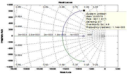
Figure 7 Root-locus map of the closed loop current control using pole-placement method.
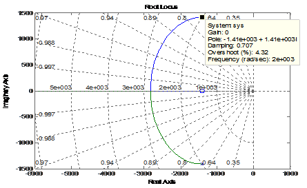
Figure 8 Root-locus map of the closed loop current control using Butterworth polynomial method.
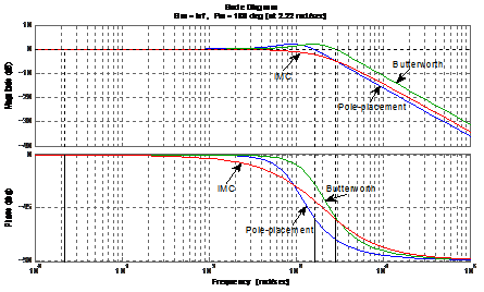
Figure 9 Bode plots for the three controllers’ parameters tuning methods for the inner current control.
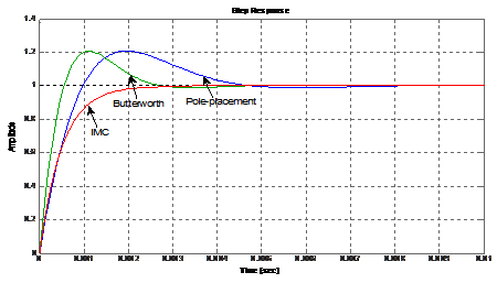
Figure 10 Step response plots for the three controllers’ parameters tuning methods for the inner current control.
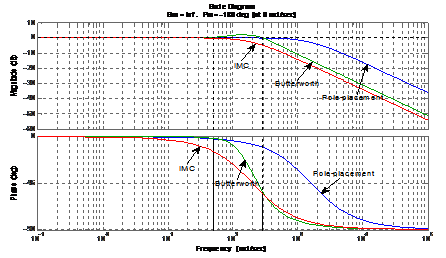
Figure 11 Bode plots for the three controllers’ parameters tuning methods for DC-link voltage control.
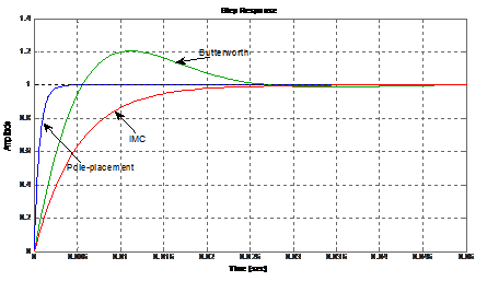
Figure 12 Step response plots for the three controllers’ parameters tuning methods for DC-link voltage control.

Discussion of results

Each of the three analytical tuning techniques for the controllers’ proportional gains, integral gains, and integration times can effectively be adopted to maintain stable system operation. The root-locus map of (Figure 7) confirms the assumed data for overshoot and damping ratio and calculated natural frequency of operation of the system for the pole-placement method. For same value of closed loop control bandwidth frequency chosen for the Butterworth polynomial and IMC methods, the Butterworth polynomial root-locus map of (Figure 8) share similar characteristics with that of (Figure 7). These similarities can easily be observed in Bode plots of Figure 9 and step response plots of (Figure 10). Considering the current control and the DC-link voltage control, it is observed however, that while the IMC method gives better performance for the current control, the pole-placement method gives better performance for the DC-link voltage control. The settling times (a measure of the dynamic response of system to transients) for the current control are 3x10⁻³s, 4.6x10⁻³s, and 8x10⁻³s for IMC, Butterworth polynomial, and pole-placement methods respectively. In the same order, their phase margins (a measure of the stability of feedback systems) are 180o, 127o, and 126o. Unlike the other two methods, the IMC method simulates a critical damping criterion as evidenced in Figure 10 with closed loop control negative real poles. For the DC-link voltage control, the pole-placement and IMC methods share some similarities. However, while the phase margin for the pole-placement method is 178o, the phase margin for IMC method is -180o. The negative phase margin is an indication that the use of IMC method for the DC-link voltage controller parameters results in instability of the controller system. This instability emanated from the existence of pole at the origin of the DC-link system plant. One solution for the instability is to add an inner feedback loop for active damping in the voltage control loop. The critical damping criterion of the IMC method exhibited in the current control is also extended in the DC-link voltage control. Of the three analytical tuning methods, the Butterworth polynomial method exhibits consistency in the phase margin, overshoot, and damping ratio for the current control and DC-link voltage control.

Conclusion

Detailed study of analytical tuning of controllers for grid-coupled voltage source converter has been carried out. It is concluded that any of the three methods under study can effectively be adopted for good performance operation for the control system. However, with the addition of minor loop in the DC-link voltage control loop, the IMC method presents the best option owing to its capability to simulate a critical damping criterion both for current control and voltage control. Here, the problem of controller parameter tuning is reduced to only the selection of appropriate bandwidth frequency of the closed loop control. The additional inner loop in the DC-link voltage control has been established to have the capacity to damp the DC-link current component disturbance iDC, with the same bandwidth as the DC-link voltage control loop. Due to the consistency in the phase margin, overshoot, and damping ratio for the current control and DC-link voltage control exhibited in the Butterworth polynomial analytical method, it becomes the second choice after the IMC method. Like the IMC approach, it only requires proper selection of bandwidth frequency of the closed loop control as against the initial specification of settling time and percentage overshoot prior to obtaining the damping ratio and natural frequency of system oscillation.

Acknowledgements

None.

Conflict of interest

The author declares no conflict of interest.

References

  1. Nazareno AG, Laurance WF. Brazil's drought: beware deforestation. Science. 2015;347(6229):1427.
  2. Escobar H. Water security. Drought triggers alarms in Brazil's biggest metropolis. Science. 2015;347(6224):812.
  3. Bellard C, Bertelsmeier C, Leadley P, et al. Impacts of climate change on the future of biodiversity. Ecology Letters. 2012;15(4):365−377.
  4. Keppel G, Van N, Kimberly P, et al. Refugia: identifying and understanding safe havens for biodiversity under climate change. Global Ecology and Biogeography. 2012;21(4):393−404.
  5. Franco AC, Davi RR, Lucas de CRS, et al. Cerrado vegetation and global change: the role of functional types, resource availability and disturbance in regulating plant community responses to rising CO2 levels and climate warming. Theor Exp Plant Physiol. 2014;26(1):19−38.
  6. Jung M, Markus R, Philippe C, et al. Recent decline in the global land evapotranspiration trend due to limited moisture supply. Nature. 2010;467:951−954.
  7. Gedney N, Cox PM, Betts RA, et al. Detection of a direct carbon dioxide effect in continental river runoff records. Nature. 2006;439(7078):835−838.
  8. Lammertsma EL, Friederike WC, David LD, et al. Climate forcing due to optimization of maximal leaf conductance in subtropical vegetation under rising CO2. PNAS. 2011;108(10):4041−4046.
  9. Arraut JM, Carlos N, Henrique, et al. Aerial Rivers and Lakes: Looking at Large-Scale Moisture Transport and Its Relation to Amazonia and to Subtropical Rainfall in South America. J Climate. 2012;25:1−14.
  10. Pan S, Hanqin T, Jia Y, et al. Responses of global terrestrial evapotranspiration to climate change and increasing atmospheric CO2 in the 21st century. Earth’s Future. 2015;3(1):15−35.
  11. Dai A. Increasing drought under global warming in observations and models. Nature Climate Change. 2013;3:52−58.
  12. Horta, Pablo R, Gilberto M, et al. Rhodoliths in Brazil: Current knowledge and potential impacts of climate change. Brazilian Journal of Oceanography. 2016;64:117.
  13. IPCC. Fifth Assessment Report of the Intergovernmental Panel on Climate Change. Cambridge Univ Press, UK; 2013. p. 1−20.
Creative Commons Attribution License

©2017 Nwosu, et al. This is an open access article distributed under the terms of the, which permits unrestricted use, distribution, and build upon your work non-commercially.