eISSN: 2576-4500


Research Article Volume 2 Issue 6
Department of Mechanical Engineering, Babol Noshirvani University of Technology, Iran
Correspondence: Pooya Azizian, Department of Mechanical Engineering, Babol Noshirvani University of Technology, Shariati St, Babol, Mazandaran, Iran
Received: August 14, 2018 | Published: November 19, 2018
Citation: Azizian P, Gorji-Bandpy M, Azarmanesh M. Unsteady simulation of axisymmetric plume expansion into vacuum and its interactions with a rigid body with hybrid particle-continuum approach. Aeron Aero Open Access J. 2018;2(6):326-332. DOI: 10.15406/aaoaj.2018.02.00067
An unsteady hybrid particle-continuum numerical method is proposed for simulation of axisymmetric plume expansion into vacuum and its interaction with the cross-section of a cylinder. In this problem, flow regime is changed from continuum to free molecular flow by expanding from nozzle into vacuum, which the former regime is addressed by finite volume method (FVM) as utilized continuum method and the latter is addressed by direct simulation Monte-Carlo (DSMC) as the particle method. In this paper, both the used continuum and particle methods are described and assessed separately. Then, we have presented the coupling method of these continuum and particle codes, that it provides the ability to simulate unsteady flow. The hybrid method has been assessed by the available steady state results that it displays adequate ability to simulate high density flow up to rarefied flow. The results of unsteady flow expansion from nozzle into vacuum is presented and analyzed. It indicates that the utilized method can handle unsteady simulation of axisymmetric plume expansion into vacuum. Also, the time evolutions of different variables are provided. Finally, the impacts of plume interaction on a cylinder surface are investigated during a period of time by studying temperature and pressure on the surface.
Keywords: hybrid method, DSMC, FVM, unsteady flow, axisymmetric nozzle, interaction
To control space objects in high altitude, a number of propulsive systems are frequently used. The thrust level of these engines is usually small. They may cause a number of harmful effects which reduce the operational lifetime of the spacecrafts significantly. Despite the fact that the firing times of these thrusters are usually a few seconds, they are fired repeatedly for many years. This may leads to the contamination from the plume on sensitive surfaces of spacecrafts.1 The assessment of the interaction between the plume and the spacecraft demands an accurate description of the expanding flowfield of plume flow and its interaction with different surfaces. Also, due to these repeated expansion of plume flows for a few seconds, understanding of the unsteady expansion of this flow regime is consequential.
The plume flow in high altitude expands into low density medium near to the vacuum condition. As the plume flow leaves the nozzle lip, it undergoes a rapid expansion, and when the plume expands the gas becomes rarefied. This phenomenon continues until it cannot be described by the continuum governing equations. As the flow is continuous it can be described by the Navier-Stokes equations or inviscid Euler equations, but when the continuity assumption is no longer true, it should be delineated by the Boltzmann equation, which is the fundamental equation of the gas kinetic theory. The Direct Simulation Monte Carlo (DSMC) is a direct particle simulation method based on this theory. The fundamental idea of this method is to track thousands or millions of randomly selected, statistically representative particles.2 The essential DSMC approximation is the uncoupling, over a small time step, of the molecular motion and the intermolecular collision.3 The numerical cost of DSMC calculations is proportional to the flow density, because the size of the computational cells must be scaled with the molecular mean-free-path, which scales inversely with the density. Hence, a high-density flowfield claims a large number of computational cells. This intends simulation of more particles and collisions. Notwithstanding the expansion of flow into vacuum, the conditions near the nozzle throat are those of a relatively high-density, continuum regime, and it leads to make the simulation of flow through nozzle quite expensive for the DSMC code. The invalidity of continuum methods in rarefied region and indomitable computational cost of particle methods in high-density region make the hybrid methods efficient. This study is based on a combination of the Finite Volume Method (FVM), as continuum method, and the Direct Simulation Monte-Carlo, as particle method. The hybrid method will have found the breakdown interface of continuum and particle methods before it applies DSMC and FVM in the corresponding regions.
In spite of considerable progress over the past decades, accurate and efficient simulation of plume flows at high altitude remains a considerable challenge.4 This is caused by numerical difficulties associated with the wide range of flow regimes faced in plume expansion into vacuum. The hybrid method takes into account due to these difficulties. The simplest hybrid particle-continuum method includes dividing domain and performing two decoupled simulations, which is used by Hash and Hassan for simulation of a hypersonic flow over a blunted cone.5 They visited this problem again by employing the coupling mechanism.6 Although they put to use the coupling mechanism, it was not strong coupling, in which the continuum domain does not affected by the particle domain. The approach of strong coupling for hybrid modeling of continuum-rarefied flow is investigated by Carlson et al.7 Latest, to unsteady simulation, Pantazis and Rusche utilized a hybrid continuum-particle solver for rarefied gas flow through a shock tube and an orifice.8 Our paper aims to apply this hybrid unsteady simulation on axisymmetric plume expansion into vacuum. Also, simulation of the interaction of this plume flow with a cross-section of a cylinder is desired. The steady state plume expansion into vacuum is simulated by hybrid method beforehand,9‒11 now this study is focused on unsteady expansion, which has not been studied significantly. Moreover, an initial assessment of plume interaction with surface of a cylinder’s cross-section in low density medium is provided.
The plume flow expanding from nozzle into vacuum is a three dimensional flow. However, due to the axisymmetric nozzle geometry and assuming zero rotational speed, it can be simulated as an axisymmetric flow. This assumption reduces the computational cost of hybrid simulation, significantly. The finite volume axisymmetric code based on inviscid Euler equation, which is written by authors,12 is coupled with the axisymmetric Direct Simulation Monte-Carlo code of Bird.13 All the codes are written in the FORTRAN programing language. In the following, we briefly describe governing equations and methods in two different continuum and particle regions and then describe applying the hybrid method in detail.
The continuum method
The governing equations for an axisymmetric inviscid flow can be written as follow:
(1)
(2)
(3)
(4)
where ρ, v and E denote the density, velocity components and the total energy per unit mass, respectively. Also, it is assumed that . The total energy per unit mass can be defined as:
(5)
that by using the equation of state for the perfect gas ( P=ρRT ), where R is the specific gas constant, the above equation leads to:
(6)
where γ is the ratio of the specific heats. Using this equation in energy equation (eq. 4) can reduces the number of variables. Consequently, there are four equations for the four independent variables vz, vr, P and ρ. Then numerical method as like as the finite volume method will be applied on the system of algebraic equations.
The particle method
DSMC is a direct particle simulation method based on kinetic theory. The basic idea is to track thousands or millions of randomly selected, statistically representative particles. Each particle is used to represent the large number of real gas molecules. In DSMC technique, the simulation region is broken up into cells, where includes particles. This method is based on unsteady computation, although steady flow may be reached as the large time state of the unsteady flow. In a time interval, particles move and collide with each other. After some time step, flow field properties will be achieved based on contribution of simulated particles. The essential DSMC approximation is the uncoupling, over a small time step, of the molecular motion and the intermolecular collision; refer to this approximation, by choosing a small time interval, that are less than the mean collision time of gas, intermolecular interactions may only occur if both of them are within the same cell.
The DSMC procedure commence by initializing molecules and boundaries. Then, molecules move within a time step and interact with the boundaries. Subsequently, molecules must be re-indexed. Later, the intermolecular collisions will be computed. The macroscopic flow properties are sampled after a large time interval. A creating geometry process is used to develop the axisymmetric Bird’s open source code by authors. This method is divided into four main sections. The solid and fluid cells are defined by the first part. The passing particles from the solid cells are detected by the second part, which is associated with the molecular motion section of the DSMC procedure. The third part finds the first crossed solid cell boundaries by the particles. The fourth section is a sub-program to reflect the detected particles from the solid boundaries, which was found in the previous section. In this section the Cercignani-Lampis-Lord (CLL) model is used to create the velocity components of the reflected particles.14,15 An axisymmetric DSMC is similar to the two-dimensional flow direct simulation in that it has two independent spatial variables, with the exception that instead of modeling unit width in two-dimensional flow, it models the full azimuth of 2π about the axis and the y-coordinate becomes the radius. Also, the three-dimensional character of the molecular paths must be considered as well.3
The hybrid particle-continuum method
In the hybrid simulation following issues must be managed: determining the breakdown interface based on the hybrid information, producing particles in the continuum domain before they enter to the DSMC domain, handling the particles which leave the DSMC domain and providing the boundary condition for the continuum method at the breakdown interface,16 which these issues will be addressed in follow.
The breakdown interface of methods: It is identified that a continuum method is invalid when the Knudsen number is large. This happens for flows with low density and/or small characteristic length scales. Indeed, a large Knudsen number means that there is not enough physical space to allow the gas to undergo a sufficient number of collisions to maintain equilibrium velocity distribution functions.17 The Knudsen number is the ratio of the mean free path λ to the characteristic length scale.
(7)
where for a hard sphere molecule with the diameter of d, the mean free path is as follow:
(8)
where n is the number density of gas. Using unified L to define a single overall Knudsen number can be misleading. Because of this limit, the local Knudsen number is defined with L as the scale length of the macroscopic gradients, and the gradient length local Knudsen number is as follow:
(9)
where Q is one of the macroscopic properties of the flow. The local Knudsen number is equal to the maximum of the gradient length local Knudsen number based on density, the magnitude of velocity and the transitional temperature. Previous works found that the local Knudsen number less than 0.05 is sufficient to maintain equilibrium assumption, however due to using inviscid equations and prevent the statistical error, a more conservative cutoff must be used.18 This study has utilized 0.01 as the breakdown criterion.
Coupling of the domains: After finding the interface, to produce and handle the particles for the DSMC domain and provide the boundary condition for the continuum domain, a domain coupling mechanism must be applied. To do domain coupling, the method of reference16 is used. To perform the coupling, the buffer and reservoir DSMC cells are expanded in the continuum domain neighboring to the interface, which the buffer cells are closer to the pure particle domain than the reservoir cells. The buffer cells work as extension of the particle domain in the continuum domain and the DSMC calculation in them is like the rest of the particle cells. However, the reservoir cells differ, in that for each time step, all particles will be deleted and then regenerated based on the macroscopic properties of the continuum domain outputs. Also, the DSMC cells adjacent to the interface work as the ghost cells to provide the boundary condition to the continuum method.
The hybrid algorithm: For each time step of the hybrid calculation, for a time step of t to t+1, first the DSMC method must be applied to provide the boundary condition at time t+1 to continuum method, which is based on an implicit method. For this purpose, the reference8 is pursued with the exception of some modifying, because of different domain coupling. The implemented hybrid algorithm is described as follow:
First, the benchmarking of the continuum and particle solvers are provided, separately. For validation of the finite volume code, the underexpanded circular jet, which containing Mach disk, is simulated. The jet exit Mach number and the exit static pressure ratio are 1.5 and 3.15, respectively. Figure 1 shows the comparison of the obtained Mach number distribution with reference,19 which indicates desirable agreement. It indicates that a Mach disk is placed at the location of about 4.5 times greater than the jet exit radius from the jet exit location. Also, the radius of the Mach disk is approximately 0.7 times smaller than the jet exit radius. The contour value shows that the Mach number upstream of the Mach disk has accelerated to values about 4.0, but the Mach number downstream of the Mach disk is reduced to values below 0.5.
For validation of the developed DSMC code, the low density supersonic flow around the cylinder is simulated, which the free stream Knudsen number and the speed ratio are equal to 0.3 and 5, respectively. The characteristic length (L) set to the cylinder diameter. Figure 2 shows comparison of the density ratio of our DSMC code with reference,20 which are non-dimensionalized by the free stream mean free path as the reference length. It illustrates that the result has good agreement.
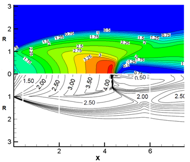
Figure 1 Comparison of the obtained Mach number of an underexpanded circular jet by FVM code with the output.19 The jet exit Mach number is 1.5, and =3.15.
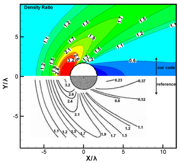
Figure 2 Comparison of the obtained density ratio by DSMC code with the output.20 The speed ratio is 5, and .
As we aimed, the hybrid particle-continuum axisymmetric simulation is performed for plume expansion into vacuum from a nozzle tested at the NASA Lewis Research center. The nozzle throat diameter is 3.18 mm and exit to throat area ratio is 100. Also, the divergent half angle is 20 degree. The studied gas is nitrogen and it considered as a perfect gas. The stagnation pressure and the stagnation temperature through the nozzle chamber are 6400 Pa and 699°K, respectively. The CLL model is implemented in DSMC region as the gas/surface interaction model. This model uses separate accommodation coefficients for the reflection of the normal and tangential velocity components. Also, the nozzle wall temperature is fixed at 550°K. The simulation region is divided to about 40000 uniform cells which are distributed between the continuum and non-continuum regions depend of time. Also, the total number of simulation particles will change depend on time; however in steady state situation, it is approximately half million. Furthermore, the time step is kept constant and equal to .
Steady state validation
Figure 3 compares part of the region of steady state Mach contour of this study with reference.21 It shows desired agreement to confirm validity of the hybrid particle-continuum method and the utilized simulation code. Flow in the convergent nozzle and at the beginning of the divergent nozzle is low Knudsen number flow and consequently it is continuum. However, in most of the divergent nozzle, the continuity assumption is not established. Figure 4 provides Knudsen number, stream lines, pressure and density contours clockwise from top left, respectively. The flow regimes vary from continuum, at the nozzle throat, to rarefied, in the plume. The Mach number contour reveals that the sonic line intersects the nozzle lip. Moreover, it is observed that the boundary layer along the nozzle wall is thick. The hybrid solution indicates a significant velocity slip at the nozzle lip. And, the rapid expansion is illustrated by the large turning of the streamlines at the nozzle lip.

Figure 3 Comparison of the steady state Mach contour of plume expansion into vacuum from a convergent-divergent nozzle, up: this study, down: adapted from reference.21 The stagnation pressure and temperature in chamber are 6400 Pa and 699°K.
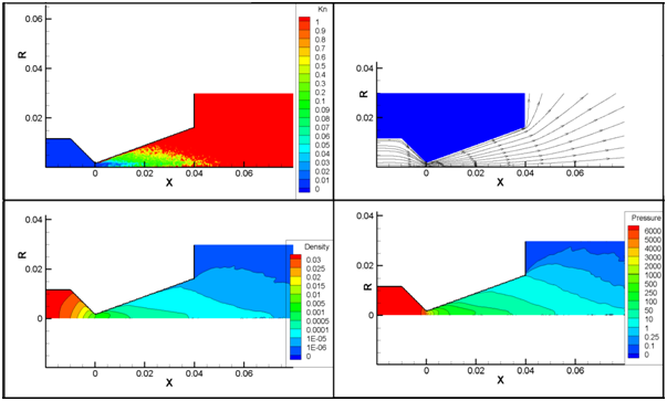
Figure 4 Obtained steady state results by Hybrid code. Knudsen number contour, stream lines, pressure contour and density contour clockwise from top left.
Obtained by the hybrid simulation, the stagnation pressure profiles at the nozzle exit plane were compared with the experimental results of the reference,1 which were measured by a pitot tube (Figure 5). The stagnation pressure, which is a function of static pressure and kinetic energy, is non-dimensionalized by stagnation pressure through the nozzle chamber. It shows errors near the center line and the nozzle wall due to reducing in the number of simulated particles and the gas/surface interaction model, respectively.
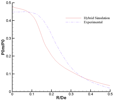
Figure 5 Comparison of the obtained non-dimensionalized stagnation pressure profiles with the output adapted from reference.1
Unsteady simulation
Unsteady expansion of the gas flow from the nozzle into vacuum is investigated. Initial condition is static gas with stagnation condition in the chamber before the nozzle throat and the absolute vacuum after the nozzle throat. No appropriate experimental data or previous simulations for unsteady expansion from nozzle into vacuum are available for comparison with this unsteady solution. However, the results provide an initial assessment of the unsteady expansion of the plume flow from nozzle into vacuum. Following, variations of two important dimensionless numbers of gas flows over time have been studied. Figure 6 displays Knudsen number changes over time. At first, due to the initial conditions, Knudsen number in the left side and the right side of the throat are close to zero and infinite, respectively. In the vicinity of the breakdown interface, because of the large gradient of the gas properties, the Knudsen number is large, which this range is the transition zone from continuum to free molecular flow. Gradually over time, due to the difference in pressure, the gas flow rapidly expands into vacuum. Then, effects of this expansion limit the progression of the continuum region into vacuum. If the Knudsen number 1 is considered as the boundary of the free molecular flow, this region of time of 50 microseconds to be fixed later. However, the flow is not steady yet because the flow variables will change. Also, the breakdown of continuum method can be found at the Knudsen number of 0.01, which is located on the right side of the nozzle throat inside the divergent nozzle.
Figure 7 shows Mach number changes over time. With starting gas expansion in divergent nozzle, the highest velocity occurs in the vicinity of vacuum, where there is not the intermolecular counterpoise. At the beginning of the expansion, due to the lack of continuity in dilute gas, high speed stream can be seen near the nozzle wall. However, Velocity decreases there with time, because gas penetration into the divergent nozzle increases the concentration of the gas molecules, gradually. At the Nozzle lips, at first the maximum turning angle is low, but over time in order to increasing ambient density it will increase. Finally, increasing number of gas particles leads to decreasing the effects of random movement of particles on macroscopic properties and the maximum Mach number will be reduced.
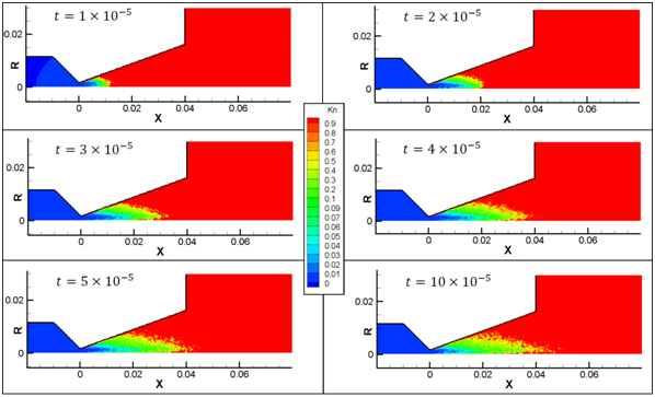
Figure 6 Knudsen number changes over time of unsteady expansion of the gas flow from the nozzle into vacuum.
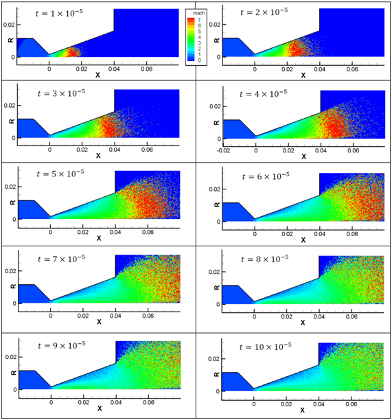
Figure 7 Mach number changes over time of unsteady expansion of the gas flow from the nozzle into vacuum.
Figure 8 indicates the Mach number contours at 0.5 microseconds with different ratios of real gas molecules to simulation particles . It is observed that the ratio of 1012, unlike the ratios of 1011 and 1010, cannot simulates this unsteady flow properly, because the presence of less than 20 simulation particles in each cell will result in high statistical error. Also, the statistical error near the symmetry axis is more than the rest of the domain, for the reason that the smaller cells near the symmetry axis lead to the existence of less particles there.
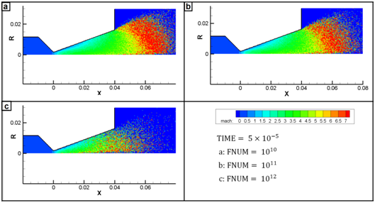
Figure 8 Effect of the ratio of real gas molecules to simulation particles on simulation results in a specific time.
Plume interactions with a rigid body
Finally, interaction of unsteady plume flow, which is in a situation as same as the previous section, with a rigid cross-section of cylinder is simulated. Figure 9 illustrates Mach number contours of the starting plume flow, which interacts with a cross-section of cylinder with a radius of 1 mm and at the distance of 1 mm from nozzle exit. It shows that the interaction begins at the time of . Also, in the further time steps, flow speed decreases in front of cylinder cross-section, and in a contrary manner, it increases at the cylinder lips. By comparing with the unsteady expansion without presence of cylinder, we can perceive that although there is not difference before than the time of in the flow patterns, the plume expansion is diminished in additional times.
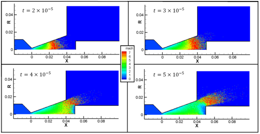
Figure 9 Mach number contours of the interaction of the starting plume flow with the cross-section of a cylinder.
Variation of temperature and pressure on the surface of cylinder’s cross-section are considered. Figure 10 indicates temperature of surface along the radius of cross-section for different time steps. At the time step of , temperature commence to fluctuate, because of arriving the gas molecules. In the following times, temperature drastically increased, up to more than 1000°K. Low temperature near the symmetry axis is due to lack of enough particles in the very small cells which are located there. This intense increase in temperature shows importance of the study of plume flows’ interaction with sensitive segments of spacecrafts and satellites.
Figure 11 depicts pressure on the surface of cross-section for different time steps. After the time step of , pressure on the surface is begun to increase by interaction of gas molecules. As it is expected, pressure values are not high, due to free molecular flow. Moreover, it shows that by marching from cylinder center to cylinder lips along the radius, the pressure value is decreased.
An unsteady hybrid particle-continuum method has been utilized for simulation of axisymmetric plume expansion from a nozzle into vacuum and its interaction with the cross-section of a cylinder. The validation has been performed with the steady state problem and the agreement is adequate. The unsteady results provide an initial assessment of the studied flows. Knudsen number is changed over time that it reveals the location of the continuum method breakdown. It is observed that when ratio of the simulated particle numbers to the real gas molecules is excessively low, the method cannot simulate it properly. Also, the statistical error near the symmetry axis is more than the rest of the domain. Finally, simulation of the plume flow interaction with the cross-section of a cylinder reveals that an intense increase in surface temperature will occur, which is crucial for predictions in space technologies.
None.
Authors declare that there is no conflict of interest.

©2018 Azizian, et al. This is an open access article distributed under the terms of the, which permits unrestricted use, distribution, and build upon your work non-commercially.