
Review Article Volume 2 Issue 4
Undercarriage heat power in aircraft landing
Weiji Wang
Regret for the inconvenience: we are taking measures to prevent fraudulent form submissions by extractors and page crawlers. Please type the correct Captcha word to see email ID.

University of Sussex, England
Correspondence: Weiji Wang, University of Sussex, Brighton BN1 9QT England
Received: June 06, 2018 | Published: July 17, 2018
Citation: Wang W. Undercarriage heat power in aircraft landing. Aeron Aero Open Access J. 2018;2(4):215-221. DOI: 10.15406/aaoaj.2018.02.00053
Download PDF
Abstract
This paper analyse the energy flow which generates heat and causes wear during the acceleration period of undercarriage wheels after aircraft touchdown on the runway. In this acceleration period, a sliding between the wheel tyre and runway surface takes place. The sliding friction causes high temperature which emits pollution smoke and produces excessive tyre wear. A model based on mechanical dynamics is established for analysing the high temperature, heat transfer rate to tyre and concrete runway. The effect of adopting a pre-rotation device is also analysed in order to lower the temperature and reduce the tyre wear. The width of tyre is shown also having significant effect on the raised temperature. A blackened runway is believed to have changed the heat conduction therefore affecting the landing quality.
Introduction
During aircraft landing, significant high tyre temperature rises when the undercarriage is just touching down the runway. The sudden acceleration of wheels is accompanied by smoke and excessive wear, not just emitting pollution particles to surrounding air but depositing carbonized rubber on the runway. The high temperature weakens the tyre strength, even melts the rubber and brings about more rubber losses. With the number of landing increases, the touchdown area on the runway is usually severely blackened with deteriorated surface friction and heat dissipation properties. Normal practice is to use torch to burn off the rubber in scheduled intervals, which incurs extra airport operating cost and reduces airport operating efficiency. On the other hand, the tyre life is reduced due to such intensive wear, bringing other additional costs from high frequency of changing tyres. A number of invented designs for pre-rotating aircraft landing wheels have been proposed since the 40s of 20th century, which promisingly solve such problem effectively.1‒15 The power source for spinning the wheel has been proposed from side wind turbines, electric motors, etc. However, the real application is generally lacking and has to be looked forward into the future. Some attention to the problem still exits mainly in aviation engineering research and environment quality areas.16‒18 Recently, the science and technology behind the pre-rotation have been systematically investigated and some solutions have been developed.19‒24
With current static wheel in landing, the ground friction has to spin the wheel to match the landing speed with the same tangential speed. The limited friction is always below the demand of instant acceleration which in theory needs an infinitely strong force, therefore a sliding inevitably takes place, which grinds rubber away from tyre surface softened and burnt by high temperature at the touch area. The reported research in the references19‒24 has covered finding the effectiveness of the technique of pre-spinning the wheel to reduce the tyre tread heat and wear, and choosing the initial wheel rotation speed that prevent the tread rubber from melting temperature. For achieving this, a coupled structural–thermal transient analysis in well-known software package ANSYS has been used to model a single wheel main landing gear as a mass-spring system. The model has been chosen to analyse the wheel’s dynamic behaviour and tyre tread temperature and wear during the short period from static to a matching free-rolling velocity in which the wheel is forced to accelerate by the friction between the tyre and ground. The tyre contact surface temperature and wear have been calculated for both the initially static and pre-spun wheels in order to compare the temperature and wear levels for different initial rotation speeds.
The required torque to spin the aircraft wheel to the required angular speed at approaching speed has been calculated using ANSYS CFX, which is used to determine the wheel aerodynamic forces developed by simulation of fluid flows in a virtual environment. Several types of side wind turbines have been simulated using ANSYS CFX in order to optimize with regard to the geometry, target rotation speed, and required acceleration. In one type of the wind turbines, air flow is being guided positively to increase the torque. Simulation and application of Savonius turbines25 have been taken example. This paper is addressing the effect of sliding displacement and mechanical work done by the ground friction. The heat due to wheel sliding is transferred to both tyre and concrete ground. Relatively higher heat conductivity and mass capacity of runway can actually ease the high temperature by taking a portion of the sliding energy. Both the wheel tyre and runway play the role in conducting and absorbing the heat during the acceleration period of undercarriage wheels. However, the energy intensity of the temperature rise which causes smoke and wear to the tyre is the main focus.
Total wheel tangential displacement and actual ground displacement during acceleration
For modern aircraft, instantly after the landing gear touches the runway, it is for the ground friction to provide a torque to accelerate the static wheel to match the landing speed within between a fraction of a second and a couple of seconds. The acceleration time is depending on the wheel inertia and geometry, ground friction and other resistance such as from its shaft, surrounded air viscosity and ground rolling resistance. The runway is normally a concrete rough surface. No matter how great the friction can be provided, the torque by the ground friction is always limited. It needs some time to accelerate the wheel from static to a tangential speed to match the required aircraft landing speed. During the acceleration, the tyre has to slide before reaching the landing speed.
Let
be the aircraft landing speed and
the angula0072 speed of the landing gear wheel. When acceleration is completed after touchdown, the tangential speed of wheel at touch point relative to shaft becomes also
. Assuming the friction provided by the runway ground
, where µ is the sliding friction coefficien t, depending on type of tyre, contact area and runway condition, and assumed to be constant for simplicity; W is the vertical force share on the wheel shaft due to weight of aircraft, which normally has multiple wheels, as shown in Figure 1. For a usual soft landing, W is much lighter during the wheel acceleration period than the full weight share of a wheel.
After the touch instant, using the classical Newton’s second law of motion for rotational circumstances, with a resistance torque Tr which includes those friction in shaft, air viscosity and ground tyre rolling resistances, the equation can be described as
(1)
where I is the moment of inertia of the whole wheel, r is the radius. This radius is regarded as the effective radius, having taken into account of tyre deflection. It is the friction between the concrete runway and rubber tyre that accelerates the wheel to a matching landing rotational speed within ts by limited torque
. During this acceleration time, sliding exists as at the beginning the wheel is accelerated from static. In the late stage of acceleration, sliding approaches 0 as the wheel’s tangential speed is matching the aircraft speed, which is also the speed of wheel shaft. The wheel needs a period of time to accelerate to
as the ground can only provide a limited, not unlimited, friction F. Although the ground friction is changing according to the sliding speed, usually the faster the smaller, for simplicity, a flat average constant can be assumed. The sliding time ts = 0 only if the ground could provide infinitive friction to generate an infinitive acceleration from static to
, which is impossible. Therefore, a sliding is inevitable. During this acceleration period with part wheel sliding can be assumed to be accelerated uniformly for simplicity. The resistance torque Tr also is regarded as being averaged to a constant. The wheel angular acceleration becomes:
(2)
The angular velocity of wheel can be calculated from the integration:
. Then the tangential velocity is
(3)
The sliding velocity is the difference relative to the required tangential velocity as
(4)
Let ts be the required acceleration time, also assumed the angular acceleration is uniform from static. Eventually the acceleration is completed, i.e. there is no sliding any more:
, the required acceleration time is:
(5)
Considering a pre-rotation is applied. Letting
(
) be the pre-rotation ratio, i.e., the percentage of landing speed
being pre-rotated by a whatsoever pre-rotation device, and ts will be the required acceleration time from 0 or a slow spinning speed, to the matching landing speed
. With the pre-rotation, the tangential velocity and the sliding velocity are, respectively,
(6)
(7)
Therefore, with pre-rotation, the required acceleration time is:
(8)
From the above equation, a shorter
can be expected if a pre-rotation as
is between
at t=0 and 0 at t=ts. The average sliding velocity over the acceleration time
is:
(9)
As described in the introduction section, several types of devices have been proposed for the pre-rotation. For example, a side Savonius wind turbine is suggested to fit on the wheel, on which an air dynamic torque is generated to accelerate the wheel to achieve a tangential speed reached or close to the landing speed before the touchdown. After the touchdown, no energy or just smaller energy (depending on the pre-rotation ratio) is required to accelerate the wheel to the matching speed
. Even partial pre-rotation is implemented; the temperature can be significantly reduced. The high temperature which causes rubber melting or burning off can be avoided. If the pre-rotation level
,
; it usually takes as long as a fraction of second for a real aircraft to accelerate. If
,
. i.e. no acceleration time is needed, no sliding exists nor heat and smoke will be generated. Certainly, pre-rotating the wheel will reduce the acceleration time
, during which there is a sliding. The total acceleration distance, or aircraft travelled distance with sliding is
(10)
The acceleration distance
contains sliding as the wheel is gradually increasing its tangential speed from
. Since the wheel is in the state of sliding, the actual tangential displacement of wheel at contact point pushed by ground friction,
, is less than the acceleration distance
. With the average speed during the acceleration
and acceleration time
, it can be obtained the tangential displacement of wheel relative to the wheel shaft, or the tangential displacement is:
(11)
It can be defined a follow up ratio to describe how much percent the rolling distance the wheel has caught up the acceleration distance:
(12)
Also a sliding ratio can be defined to describe the level of sliding as
(13)
It describes how much percent of acceleration distance the wheel has slid for. If without pre-rotation,
=0, it can be obtained
, and
, i.e. the wheel is 50% of followed-up and 50% of sliding. If
=0.5, it can be obtained
, and
, i.e. the wheel is 75% of followed-up and 25% of sliding. In the case of
=1 with full pre-rotation,
and
, the wheel is 100% of followed-up and 0 of sliding.
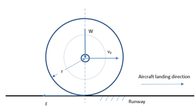
Figure 1 Aircraft undercarriage wheel at landing.
Kinetic work and sliding work
Only part of the friction is contributed to push the wheel to gain the angular rotation and stored as kinetic energy, that is
, named kinetic work, is
(14)
In the hypothetical cases of friction torque
, combining Eq.(2), the kinetic work is
, i.e. the kinetic energy gained by the wheel from the ground friction work. Without a full pre-rotation,
. The acceleration displacement caused by the forces acted on the touch point during the whole period (
) is
. Therefore, the total work done by the ground friction at any time
,
, is
(15)
At t=ts,
. The rate of work done by the ground friction,
, i.e. the power, becomes
(16)
At t=0,
, and at t=ts,
.
The instantaneous rate of sliding work, or the instantaneous sliding power, is
, i.e.
(17)
During the acceleration period (
), the aircraft displacement at time t is
, and the tangential displacement of wheel is the average speed multiplied by the time, i.e.
, where the average tangential velocity of wheel is
. Therefore, the sliding distance is
. The sliding velocity then is
. The average sliding power can be obtained as
(18)
The total sliding work is
, i.e.
(19)
Alternatively, using Eq. (10) and (11), the total sliding work at the touch point
is , Eq.(19) can also be obtained. Using the average sliding power
, Eq.(18) can also be obtained. This part of energy,
, generates heat and smoke, and causes tyre wear. During the acceleration period, the wheel has gained kinetic energy from the ground friction as
if Tr=0. In the case of zero pre-rotation,
,
. After the acceleration period, this energy will be eventually dissipated in the subsequent braking in the late stage of running after the acceleration period, which is outside this topic. The total work done by ground friction force in the wheel acceleration period is
(20)
Using Eq.(14) and (19), the total ground friction work is:
(21)
If without pre-rotation,
, the total energy will be
. In the case that Tr is small and can be ignored,
. i.e. in this case, the total work done by the ground friction is the twice of the kinetic energy gained by the wheel during the acceleration period. Only the second term in Eq.(20), i.e. the energy
, causes the high temperature, then smoke and wear problems.
Heat transfer at the contact area of tyre and runway
Sliding friction is a complicated subject. Two surfaces of bodies are interacting with physical and chemical processes. In the interfacial media, tribo-chemical reaction, such as smoke in the intensive cases like aircraft landing, takes place and tribo-particulates are also generated. In the adjacent solids of two contacted bodies, there exist deformation, fatigue and fracture.26 In aircraft landing cases, due to high speed, the sliding friction causes significant temperature rise, smoke and excessive tyre wear. The sliding friction originally causes substance losses but the high temperature intensifies such losses, partly burned off as smoke and partly torn off as particulate matter deposited on the runway surface. The rubber tyre is relatively thin, the heat is transferred to the whole depth of circumference but the runway is normally thick, it gives too short time to transfer heat to its whole depth. The heat generated by the sliding also dissipates to the runway, normally made of concrete with a higher heat transfer coefficient than the tyre rubber. Consequently, the heat affected depth is greater than the rubber tyre.
Assuming the width contact is b, which is regarded as the tyre width. The average sliding power is
, which is the heat generating rate by ground friction, contributing to the tyre and runway heat. This heat will give a significant temperature rise to both rubber tyre and runway concrete body. The heat transfers to the rubber and to runway of contact area are, respectively,27
(22a)
(22b)
where
and
are the heat conduction coefficients of rubber and concrete respectively,
and
are the higher and lower temperature sides, or hotter and colder sides, respectively.
is also the surrounding temperature.
and
are the contact area between tyre and runway surface,
are the thickness of tyre and affected concrete runway surface. Using Eq.(22a) and (22b) the heated depths for the rubber tyre and concrete runway are respectively,
(23a)
(23b)
If assuming
and
, it can be arrived
(24)
It is evident that the blackening of runway will reduce the heat conductivity of runway surface therefore may intensify the touchdown temperature. To find the contact side temperature of tyre, from Eq. (22a), the highest temperature of contact area is
(25)
Assuming
, the instantaneous temperature is
(26)
At t=0,
. At t=ts,
. i.e. There is no temperature rise. An average temperature rise can be obtained using average sliding power during ts. Thus
. Considering strong forced convection happens during the landing, the heat flow
is largely reduced, a factor, 0<φ<1, must be introduced, therefore, the hotter side temperature of tyre is
(27)
From outer surface to inner surface of tyre, the temperature ranges from Th to T0 linearly according to Newton’s conduction law. Figure 2 illustrates the temperature gradient of tyre and runway contact surfaces. The bottom layer of highest temperature easily reaches a smoke point. The thickness of lost rubber depends on Th and temperature gradient, i.e. the depth σ which has been softened or reached the smoke point. Since the thermal conductivity of concrete is about twice as much as the rubber and the contact area is larger, this tends to deepen the heated concrete surface. However, the heat on the runway can be spread to surroundings. And during the whole wheel acceleration period, the total contact area of runway is larger than that of tyre. Considering that the contact area is the whole circumference of tyre, the damaged rubber mass is
(28)
where
is the rubber density. All aircraft suffer from such losses for each landing except a pre-rotation is applied. A part of damaged mass is likely to be melt or burned off, and the other part may be torn off to print on the runway.
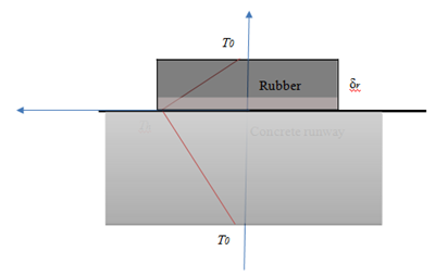
Figure 2 The temperature gradient in tyre and runway contact areas.
Landing interpretation of numerical example
The touchdown temperature against several parameters has been calculated based on meaningful Boeing passenger aircraft undercarriage data.28 The following figures are used in the following example: A soft landing friction force F=4.49×10⁴N and the landing speed v0=80.8m/s. The heat conduction coefficients for rubber and concrete
are . The moment of inertia of wheel is I=46.19kg-m2, the wheel with tyre radius r=0.622m. The density of tyre rubber is
. With 10% of resistance torque Tr applied, without a pre-rotation, it can be worked out the acceleration time
s, the angular acceleration is 163rad/s.
Figure 3 shows the tangential velocity and sliding velocity change with the time. The tangential velocity
is corresponding to the initial touch instant t=0. The sliding velocity
at t=0 is at the maximum of 80.8m/s, i.e. the aircraft landing speed, while at the end of the acceleration, the
=0, i.e. the sliding is finished, the wheel has reached a required velocity, exactly equal to the touchdown speed.
Figure 4 is the acceleration time against the pre-rotation ratio. This required acceleration time is decreasing linearly with the pre-rotation ratio from 0.8 seconds to 0 seconds. It can be seen that a 50% pre-rotation ratio can halve the acceleration time. To shorten this acceleration time ts, according to Eq. (8), the acceleration can be increased by a harder landing or a pre-rotation is applied. Since the friction coefficient between the rubber tyre and concrete runway is limited, a landing with harder suspension spring will generate more heat. Obviously, a pre-rotation will be ideal to reduce the acceleration time so as to reduce the heat.
Figure 5 displays the acceleration distance against the pre-rotation ratio ε. It decreases linearly with an increased pre-rotation ratio. The wheel tangential displacement is a half of the total acceleration distance without pre-rotation ε=0, which means a sliding exists. The follow-up ratio is 0.5 without a pre-rotation but reaches 1 with a full pre-rotation ε=1. A follow-up ratio of 0.5 indicates half of the distance is reached by rotating and half is by sliding. Since the wheel is in the state of sliding, the actual tangential displacement of wheel at contact point pushed by ground friction,
, is less than the acceleration distance
. The sliding ratio is 0.5 without a pre-rotation but reaches 0 with a full pre-rotation. Similarly, a sliding ratio of 0.5 means the distance is reached by half sliding and half rotating.
Figure 6 shows the kinetic work and sliding work done by the ground friction, respectively. The kinetic work is absorbed by the wheel as the form of kinetic energy, which will not generate heat during the acceleration stage. It is the sliding work that is the source of heat of raising temperature of the tyre and runway. They share a half each of the total friction energy at the pre-rotation ε=0, as high as 433kJ. The total work done by the ground friction force is 865KJ. The average sliding power at ε=0 is 545KW, which is a powerful source to generate high temperature. This is equivalent to the engine’s power of 2 large trucks. However, this high power generated by the ground friction is mitigated by strong wind blowing over the tyre, i.e. a strong forced convection is applied. Hence the actual power is much lower in heating up the tyre.
Figure 7 shows the highest temperature of tyre outer layer. But it reduces with an increased pre-rotation ratio ε. There will be no temperature rise at all if a full pre-rotation is applied. Obviously, a certain degree of pre-rotation is likely to drop the highest tyre temperature below smoke point. This has just demonstrated the significance of fitting a pre-rotation device, either a side-wind turbine, a pneumatic or electric motor. Of course, in latter cases, power sources and added weight must be considered.
Figure 8 tells the temperature rise is related to the tyre width. The temperature rise is reduced when tyre width is increased because the area of contact increases. This can be explained by Eq. (27). The actual contact area between tyre and runway surface,
, has been increased so that the ground friction generated heat has been shared by a wider area.
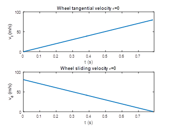
Figure 3 Wheel’s tangential velocity and sliding velocity.
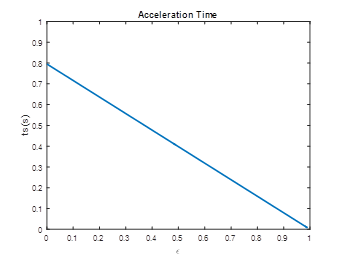
Figure 4 Wheel’s acceleration time against pre-rotation ratio.
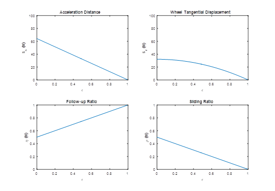
Figure 5 The acceleration distance, wheel tangential displacement against pre-rotation ratio, follow-up ratio and slip ratio against pre-rotation ratio.
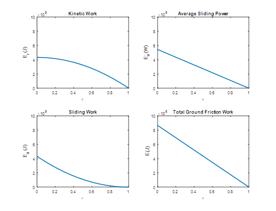
Figure 6 The kinetic work and sliding work done by the ground friction, the total ground friction work against pre-rotation ratio, and the average sliding power against pre-rotation ratio.
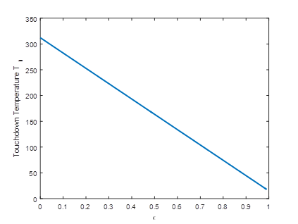
Figure 7 The touchdown highest temperature on tyre against pre-rotation ratio.
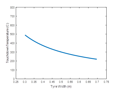
Figure 8 The touchdown highest temperature against tyre width.
Discussion
The depth of damaged tyre layer by intense heat during landing depends on the maximum temperature and its gradient, i.e. it depends on how deep the rubber molecules have reached the breaking down point. In the range of 250~400℃, tyre rubber will generate smoke and decompose oil. Higher than 400℃, more carbon particulate is formed. If in each landing, 0.2mm depth of rubber is lost, a total rubber loss is approximately, using
, 440grams. The runway ground normally is very thick and under it there is infinite layer of mud and rocks. The heat affected depth of concrete by a single landing will be limited to a certain depth. Even ordinary cement concrete can withstand as high as up to 1000oC, much stronger and heat resistant than tyre rubber. However, when the touchdown area of a runway is coated with large quantity of rubber particulate matter coming off from the tyre, both the heat conductivity and friction coefficient of runway surface will be reduced, leading to higher tyre temperature. The stiffness of suspension spring will determine the friction of touchdown instant. According to Eq. (17),
, a relatively small friction reduces the sliding power at t=0, i.e.
. The hottest instant power is reduced, so is the temperature. An initial softer non-linear spring in the suspension of landing gear may help to achieve this.
Conclusion
Dynamic modelling of acceleration period of undercarriage wheels after aircraft touchdown has been approached and developed, giving fundamental relationship between the forces and motion of aircraft undercarriage. The total acceleration distance, sliding displacement and sliding velocity have been derived. The sliding power has also been derived, which is generated during the wheel acceleration period, producing heat, smoke, and causing excessive tyre wear. The analysis shows the sliding work is a part of the work done by the ground friction. During the sliding period, the wheel has also gained kinetic energy from the ground friction in order to match the landing velocity. The maximum temperature rise formula is established based on thermodynamics. The heat transfer to both tyre and runway has been analysed. Ideally, the touchdown temperature will decrease with the increase of the pre-rotation ratio linearly as effective solution for landing smoke, tyre wear and blackening of runway. The tyre width will also affect the touchdown temperature. Increase of the tyre width will reduce the temperature. Relative to tyre, the heat transferred to runway is spread wider and deeper, therefore the damage is less serious apart from caused by rubber removal activities. The knowledge in this research unveils the mechanism of landing smoke and tyre particulate emission hopefully can be used as a new attempt to find the solution for the large-scale and world-wide landing smoke problem. Further desirable move should be in finding out the required torque by side-wind turbine or other auxiliary power source, electrical or pneumatical, to drive the undercarriage wheels in laboratory and operating conditions. On-board experiment is most desirable, which will involve large scale of funding and regulatory issues, leading to significant future improvement of aircraft landing and airport operation.
Acknowledgements
Conflicts of Interest
The author declares that there is no conflict of interest.
References
- Beazley RH. Aircraft wheel spinner and control. Washington, DC: U.S. Patent and Trademark Office; 1947.
- Khal S, Khal A. Apparatus for pre-rotating aircraft tires. Washington, DC: U.S. Patent and Trademark Office; 2013.
- Sweet RM, Gilleran N, Edelson JS, et al. Integrated electric motor and gear in an aircraft wheel. Washington, DC: U.S. Patent and Trademark Office; 2014.
- Didey A. Landing gear drive systems. Washington, DC: U.S. Patent and Trademark Office; 2014.
- Karl W. Free Spinning Wheel for Airplanes. Washington, DC: U.S. Patent and Trademark Office; 2014.
- Khal S, Khal A. Apparatus for Pre-Rotating Aircraft Tires. Washington, DC: U.S. Patent and Trademark Office; 2013.
- Ushiyama I, Tawara A. Driving device for wheel of airplane. Washington, DC: U.S. Patent and Trademark Office; 2013.
- Schmitz RH. Method and System to Accelerate Aircraft Wheels Before Touch-Down. Washington, DC: U.S. Patent and Trademark Office; 2009.
- Zha G. Landing Gear Wheels with Side-Mounted Air Foils. Washington, DC: U.S. Patent and Trademark Office; 2007.
- Horvath V, Szoke B. Airplane tire saver by protrusion airfoils. Washington, DC: U.S. Patent and Trademark Office; 2006.
- Suzuki T. Airplane Wheel Unit. Washington, DC: U.S. Patent and Trademark Office; 2002.
- Lyons DE. Method of Rotating Aircraft Wheels. Washington, DC: U.S. Patent and Trademark Office; 2002.
- John M Opitz. Airplane Wheel Rotator. Washington, DC: U.S. Patent and Trademark Office; 1975.
- Almen Michael D. Wheel Rotation Device. Washington, DC: U.S. Patent and Trademark Office; 2002.
- Gannatal JP. Space Shuttle Wheel Acceleration System. Washington, DC: U.S. Patent and Trademark Office; 1993.
- Gooding D, Singh K, Wilson S. Development of a Windmill Machine Pre-Rotation Device for an Aircraft Nose wheel. The Journal of the Association of Professional Engineers of Trinidad and Tobago. 2011;40(2):49–56.
- Bennett M, Christie SM, Graham A, et al., Composition of Smoke Generated by Landing Aircraft. Environ Sci Technol. 2011;45(8):3533–3538.
- Broitzman T. Self-Rotating Aircraft Tire that Spins up Prior to Landing; 2009.
- Alroqi AA, Wang WJ. The prevention of aircraft tires overheating by pre-rotating the wheels. London: 7th International Conference on Mechanical and Aerospace Engineering; 2016. 443–447 p.
- Alroqi AA, Wang WJ. Reduction of Aircraft Tyre Wear by Pre-Rotating Wheel Using ANSYS Mechanical Transient. Advanced Engineering Forum. 2016;17:89–100.
- WJ Wang. Dynamics and Energy Conversion of Aircraft Landing Gears at Touchdown. UK: 3rd International Conference on Mechanics and Mechatronics Research; 2016. 4 p.
- Abdurrhman AA, Weiji Wang. Comparison of Aircraft Tire Wear with Initial Wheel Rotational Speed. International Journal of Aviation, Aeronautics, and Aerospace. 2015;2(1).
- Alroqi AA, Wang WJ. Pre-Rotation Wind Turbine Design and Optimization for Aircraft Landing Gear. Advanced Engineering Forum. 2017;23:88–103.
- Abdurrhman AA, Weiji Wang, Yong Zhao. Aircraft Tire Temperature at Touchdown with Wheel Pre-rotation. Journal of Aircraft. 2017;54(3):926–938.
- Altan BD, Atilgan M. A study on increasing the performance of Savonius wind rotors. J Mech Sci Technol. 2012;26(5):1493–1499.
- Peter J Blau. Friction Science and Technology: From Concepts to Applications. 2nd ed. Florida: CRC Press; 2008. 432 p.
- Yunus AC, Michael AB. Thermodynamics: An Engineering Approach. 7th ed. New York: McGraw-Hill Higher Education; 2014. 1024 p.
- Approach speeds for Boeing airplanes. Chicago: Boeing Commercial Airplane Co; 2011. 4 p.

©2018 Wang. This is an open access article distributed under the terms of the,
which
permits unrestricted use, distribution, and build upon your work non-commercially.


