eISSN: 2576-4500


Research Article Volume 6 Issue 3
Director, DEDALOS Ltd, Greece
Correspondence: Konstantinos Katsonis, Director, DEDALOS Ltd, Thessaloniki, Greece
Received: July 13, 2022 | Published: July 27, 2022
Citation: Katsonis K. Support of Solar system study by using ISRU based electric propulsion. Aeron Aero Open Access J. 2022;6(3):97-99. DOI: 10.15406/aaoaj.2022.06.00146
Support of the exploration and study of our Solar system obtained by electric propulsion using available in situ resources for harvesting of the necessary propellants is addressed. This technology should contribute to related R&D development, allowing also for exploitation of the available resources. Specifically, dedicated global models of interest and concomitant diagnostics are shortly described and discussed.
Keywords: Solar system, detailed global model, optical emission spectroscopy, electric propulsion
ISRU-EP is an In Situ Resource Utilization (ISRU) based space Electric Propulsion (EP) disruptive technology able to support ambitious space missions already in the forthcoming years. As expected, air breathing Electric Thrusters (ET) using as propellant the Earth atmospheric remnants which are composed mainly by O / N2 mixtures in varying percentages depending on the altitude,1,2 were naturally included among the first studies3 and realization projects. In this domain, the European projects AETHER4 and DISCOVERER5 have already obtained significant results.
Among ISRU-EP key technologies meant for future missions CO2 propellant, which is the main component of the Mars and Venus atmospheres, has been also early addressed.6 Importance of the CO2 propellant for ISRU was recently investigated and assessed elsewhere.7 The more remote is the harvesting region in case of ISRU the better, because in this case avoiding of a longer propellant transport is obtained. Consequently, missions involving gas giants as Jupiter but also notably Neptune, an ice giant, could obtain outstanding achievements by using ISRU technology. A mission using the ISRU-EP technology has been proposed recently in relation with the study of Neptune and of its vicinity (including notably its moon Triton).8 The necessary modeling and diagnostics support have been described in detail in9 Pluto, previously considered as a planet and other stellar bodies nearby could also benefit from this technology.
An essential tool for ISRU-EP is the Detailed Global Model (DGM) in its various forms, each one of them dedicated to a selected propellant to be collected. DGMs describe various types of plasma on the basis of a statistical equations system, as is also the case with the Collisional-Radiative (C-R) models, but the former is implemented by an energy equation. This important equation allows for the description of the energy budget corresponding to the various plasma processes and takes into consideration globally the plasma properties. Thus, the plasma sheath plays an important role in the global plasma modeling and the energy budget is coupled with the absorbed and emitted radiation. DGMs are meant to ease the EP technology by means of their main assets,7 consisting in:
In the following, an example of ISRU-EP technology as applied in the case of the giant planets exploration is presented and discussed in Section I. The basis of the concomitant optical emission diagnostics is illustrated in Section II. Common conditions encountered in propellant harvesting from the Solar system stellar bodies are briefly described in Section III. Conclusions and perspectives are given in Section IV.
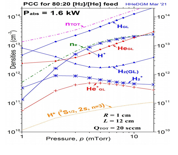
The giant planets of our Solar system have atmospheres constituted approximately by mixtures of around 80 % H2 and 20 % He. The typical case of the Neptune atmosphere is chosen here as an example. It is addressed by means of a DGM type model dedicated to hydrogen / helium mixtures. This model, HHeDGM, is developed by DEDALOS Ltd. A typical PCC diagram obtained by HHeDGM, illustrating the situation of the ET plasma when fueled by a propellant constituted by a mixture of 80 % H2 and 20 % He which is approximately the consistence of the Neptune atmosphere, is given in Figure 1 for a cylindrical form factor of radius R= 1 cm and length of L = 12 cm. Our HHeDGM model, meant for any initial mixture of hydrogen with helium (see9 and references therein), is used in this case with the hydrogen being initially in molecular state. Densities of the main constituents are given for various pressure p values for hydrogen- and helium-related components. Note that the sole excited state appearing in the figure is the first hydrogen atom metastable one. Electron densities are also shown.

Figure 1 PCC diagram for a thruster of form factor R = 1 cm and L = 12 cm fueled by 20 sccm from the Neptune atmosphere. Densities of the main constituents are given for various pressure p values for hydrogen- and helium-related components by blue and red curves correspondingly. Densities of metastable excited hydrogen are given in orange. Also, total densities are shown by a magenta curve and electron densities by a green curve.
We observe in Figure 1 that the most present species is H in its ground state, except in the 1 mTorr region, a region where the molecules are still not quite dissociated. Besides H2 dissociation, the quite high absorbed power of Pabs = 1.6 kW is mostly spent to ionize the created atomic hydrogen than the existing He, especially for increasing pressure values. Then, the most important processes are dissociation of the H2 and ionization of the hydrogen, with the bulk of the obtained H2 and He ionization being quite lower.
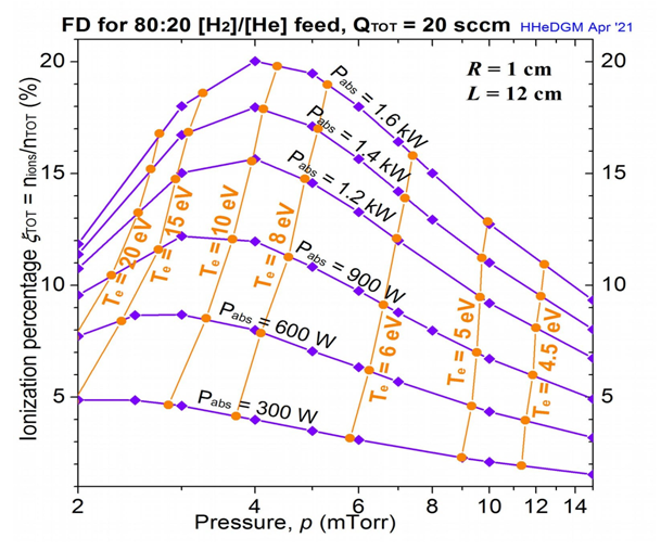
Data from PCC diagrams corresponding to various Pabs and Te values lead to the condensed FD diagram of Figure 2. It presents the total ionization percentage of the plasma for a flow rate of 20 sccm (standard cubic centimeter per minute) fueling under various conditions of Pabs and of Te , for pressure values going from p = 2 mTorr to p = 15 mTorr, essentially the same as those addressed in Figure 1.
Figure 2 illustrates results for absorbed power values spanning a region from 0.3 kW to 1.6 kW. Notice that the corresponding electron temperatures vary in a quite large domain, from Te = 4.5 eV to Te = 20 eV. It can be seen that for low Pabs values the provided power is insufficient to result in satisfactory plasma ionization when the pressure p increases, as Pabs is mostly spent to various chemical reactions, with the ionization remaining low. Note also that once the propellant feed is selected, the ionization level depends on the total pressure and on the absorbed power.

Figure 2 FD diagram for a thruster fueled by 20 sccm from the Neptune atmosphere. Absorbed powers Pabs are given by blue iso-power curves with diamonds. Electron temperatures Te are given by orange iso-thermal curves with full circles.
DGMs provide notably support for OES of the ETs plasma as they calculate, the line intensities of the theoretical spectra which belong to the main plasma components simultaneously with the plasma composition. This allows for a permanent monitoring of the thruster from the mission basis through a simple spectroscopic device resulting to evaluation of the obtained thrust. Note that the erosion affecting the ET can also be evaluated by inspection of the radiation emitted by the plasma and comparison with results from the DGM expanded to contain the impurities.
As an example, a theoretical spectrum is shown in Figure 3, giving the intensities of the main spectral lines of H I, He I and He II. These were obtained by HHeDGM for 1.6 kW absorbed power, when the thruster is fed by the same Neptune atmosphere constituents which have been used in the case of Figure 1. A pressure of 4 mTorr is selected which, according to Figure 2, gives the optimum ionization results. In order to obtain OES diagnostics of the thruster plasma, the calculated theoretical spectra must be compared with measured experimental ones.

Figure 3 Theoretical spectra containing the intensities of the main spectral lines of H I (red lines) and of He I and He II (green lines for both) for 1.6 kW absorbed power, for a thruster fueled by the Neptune atmosphere constituents as is the case in Figure 1.
In general, the obtained hydrogen density is orders of magnitude higher than these of the H ions and of the He ions, see Figure 1, resulting to much smaller values for the helium spectral line intensities. Intensities shown in Figure 3 have been multiplied by 10 in the case of the He II resonant lines, in order to be easily appreciated. Inversely, the intensities of the VUV resonant lines of He I and H I are shown divided by 100.
The right part of Figure 3 shows the region of higher wavelength spectral lines, containing transitory spectral lines for both neutral species, which have quite lower values than the resonant ones. Moreover, according to Figure 1 H I lines refer to a species presenting densities of about one order of magnitude higher than those of He I. This is one reason for obtaining higher intensities for former than for the latter, as in the right part of Figure 3.
Two typical ISRU cases for ET propellants from Solar system bodies atmospheres are often encountered:
Unlike to the chemical propulsion, where the propellants contain the necessary chemical energy, additional electric energy must be provided in the EP case. It must be noted that for regions quite distant from the Sun, e.g. for missions to ice giants systems and moreover for propellants which could spend significant part of the provided electric power in chemical reactions (as is the case with the mixture of 80 % H2 and 20 % He of our example), energy resources other than the captured Solar energy must be sought. In this context, it is worth to be mentioned that in the recent successful mission to Mars an additional nuclear electric energy source has been foreseen and included.
The advantages obtained when using DGMs for modeling and diagnosing of ETs functioning with propellants harvested in ISRU technology are described. A typical example of results obtained by the HHeDGM model in the case of Neptune has been shortly described and discussed, illustrating the advantages of using DGMs in ISRU-EP. Moreover, the first non-human INPPS (International Nuclear Power and Propulsion System) flagship flight with orbits Earth-Mars-Earth-Jupiter/Europa (after 2025), see e.g.10 meant to constitute the most maximal space qualification test of INPPS flagship to carry out the second INPPS flagship flight to Mars with humans (in the years 2030), could take advantage of ISRU technology by harvesting from the Jupiter atmosphere the necessary H2 / He mixture as propellant for electric propulsion.
None.
The Authors declares that there is no Conflict of interest.

©2022 Katsonis. This is an open access article distributed under the terms of the, which permits unrestricted use, distribution, and build upon your work non-commercially.