Submit manuscript...
eISSN: 2576-4500

Aeronautics and Aerospace Open Access Journal

Research Article Volume 3 Issue 4

Stability of spacecraft’s partially invariant system

Nickolay Zosimovych

Intelligent Manufacturing Key Laboratory of Ministry of Education, Shantou University, Shantou, China

Correspondence: Nickolay Zosimovych, Intelligent Manufacturing Key Laboratory of Ministry of Education, Shantou University, B8-302, Da Xue Road, Shantou, 515056, China, Tel +8613794104463

Received: September 02, 2019 | Published: October 14, 2019

Citation: Zosimovych N. Stability of spacecraft’s partially invariant system. Aeron Aero Open Access J. 2019;3(4):145-153. DOI: 10.15406/aaoaj.2019.03.00093

Download PDF

Abstract

A method for improving the spacecraft center of mass movement stabilization accuracy in the active phases of trajectory correction is proposed. This method is used during interplanetary and transfer flights, which in some cases provides high navigational accuracy, when rigid trajectory control methods are used. The required stability conditions obtained are consistent with the known criteria in the invariant theory. Computer modeling shows that a partially invariant stabilization system exhibits significant advantages in terms of accuracy when compared to known stabilization systems.

Keywords: operating device (OD), space vehicle (SV), propulsion system (PS), control actuator (CA), control system (CS), angular stabilization (AS), centre of mass (CM)

Introduction

Thriving space technology is characterized by an increasing complexity of the tasks that must be solved by modern space vehicles (SV).1 Aside from improving the navigational accuracy, the spacecraft stabilization cross errors in the active phase must be reduced, which will also result in lower total characteristic velocities of the corrective impulses and, consequently, a reduction in the fuel required for the correction. When the correction speed impulse reaches 30, a reduction in the gross error during the corrective maneuver results in a proportional reduction in the required characteristic velocity during the next correction. Previous reports2,3 showed an improvement in the accuracy of roll stabilization in the active phase by one order results in a reduction in the total characteristic correction velocity for the Mars HX-1 spacecraft from about 20 to 2m/s, which corresponds to fuel savings of approximately 30 kg or an increase in the payload mass. Due to the relatively low weights of modern scientific instruments (about 3–8), even such a seemingly small increase in the payload weight can significantly extend the research and experimental program of the spacecraft.1

Objectives: The objective is to significantly increase the stabilization accuracy of the center of mass tangential velocities during the trajectory correction phases when using the “rigid” trajectory control principle. The time of the active phase in the corrective maneuvers, which is to be determined by the required velocity impulse, is not clearly determined in advance and is quite limited. Furthermore, a guaranteed approach to enable the estimation of the accuracy is always used in practice to solve targeting tasks. Thus, we seek to understand the maximum dynamic error of the transition process in terms of the drift velocity of the spacecraft to achieve accuracy of the spacecraft center of mass movement stabilization.4

Subject of research: The subject of this research was a center of mass movement stabilization system in the transverse plane during trajectory correction phases. The control actions could be created during the spacecraft trajectory correction phase using a high-thrust service propulsion system with tilting or by moving the combustion chamber in a linear direction. The spacecraft’s movement stabilization channel in the transverse plane is based on the feedback principle, which forms a closed deviation control system with the spacecraft.1

The angular stabilization channel facilitates angular positioning of the spacecraft when exposed to disturbing moments. The purpose of the center of mass movement stabilization channel is to ensure that the normal and lateral velocities of the spacecraft under the influence of disturbing moments and forces are near zero. In most of the known spacecraft stabilization systems,5-7 the control signal in the center of mass movement stabilization channel is generated based on proportional plus integral control laws based on the measurements of the tangential velocity of the center of mass y ˙ ( z ˙ ) MathType@MTEF@5@5@+= feaagKart1ev2aaatCvAUfeBSjuyZL2yd9gzLbvyNv2CaerbuLwBLn hiov2DGi1BTfMBaeXatLxBI9gBaerbd9wDYLwzYbItLDharqqtubsr 4rNCHbGeaGqkY=wjYJH8sqFD0xXdHaVhbbf9v8qqaqFr0xc9pk0xbb a9q8WqFfeaY=biLkVcLq=JHqpepeea0=as0Fb9pgeaYRXxe9vr0=vr 0=vqpWqaaeaabiGaciaacaqabeaadaqaaqaaaOqaaiqadMhagaGaam aabmaabaGabmOEayaacaaacaGLOaGaayzkaaaaaa@3BC2@ and its integral-linear drift y( z ) MathType@MTEF@5@5@+= feaagKart1ev2aaatCvAUfeBSjuyZL2yd9gzLbvyNv2CaerbuLwBLn hiov2DGi1BTfMBaeXatLxBI9gBaerbd9wDYLwzYbItLDharqqtubsr 4rNCHbGeaGqkY=wjYJH8sqFD0xXdHaVhbbf9v8qqaqFr0xc9pk0xbb a9q8WqFfeaY=biLkVcLq=JHqpepeea0=as0Fb9pgeaYRXxe9vr0=vr 0=vqpWqaaeaabiGaciaacaqabeaadaqaaqaaaOqaaiaadMhadaqada qaaiaadQhaaiaawIcacaGLPaaaaaa@3BB0@ ;. In the angular stabilization channel, the control signal is generated proportionally to the spacecraft deviation angle in the transverse plane ϑ( ψ ) MathType@MTEF@5@5@+= feaagKart1ev2aaatCvAUfeBSjuyZL2yd9gzLbvyNv2CaerbuLwBLn hiov2DGi1BTfMBaeXatLxBI9gBaerbd9wDYLwzYbItLDharqqtubsr 4rNCHbGeaGqkY=wjYJH8sqFD0xXdHaVhbbf9v8qqaqFr0xc9pk0xbb a9q8WqFfeaY=biLkVcLq=JHqpepeea0=as0Fb9pgeaYRXxe9vr0=vr 0=vqpWqaaeaabiGaciaacaqabeaadaqaaqaaaOqaaiabeg9aknaabm aabaGaeqiYdKhacaGLOaGaayzkaaaaaa@3D29@ and the angular velocity of the spacecraft rotation in this plane ϑ( ψ ˙ ) MathType@MTEF@5@5@+= feaagKart1ev2aaatCvAUfeBSjuyZL2yd9gzLbvyNv2CaerbuLwBLn hiov2DGi1BTfMBaeXatLxBI9gBaerbd9wDYLwzYbItLDharqqtubsr 4rNCHbGeaGqkY=wjYJH8sqFD0xXdHaVhbbf9v8qqaqFr0xc9pk0xbb a9q8WqFfeaY=biLkVcLq=JHqpepeea0=as0Fb9pgeaYRXxe9vr0=vr 0=vqpWqaaeaabiGaciaacaqabeaadaqaaqaaaOqaaiabeg9aknaabm aabaGafqiYdKNbaiaaaiaawIcacaGLPaaaaaa@3D32@ .

As we think, the required dynamic accuracy of the stabilization of tangential velocities in this system is achieved through the choice of the gains in the stabilization controller k y , k y ˙ , k ϑ , k ϑ ˙ MathType@MTEF@5@5@+= feaagKart1ev2aaatCvAUfeBSjuyZL2yd9gzLbvyNv2CaerbuLwBLn hiov2DGi1BTfMBaeXatLxBI9gBaerbd9wDYLwzYbItLDharqqtubsr 4rNCHbGeaGqkY=wjYJH8sqFD0xXdHaVhbbf9v8qqaqFr0xc9pk0xbb a9q8WqFfeaY=biLkVcLq=JHqpepeea0=as0Fb9pgeaYRXxe9vr0=vr 0=vqpWqaaeaabiGaciaacaqabeaadaqaaqaaaOqaaiaadUgadaWgaa WcbaGaamyEaaqabaGccaGGSaGaam4AamaaBaaaleaaceWG5bGbaiaa aeqaaOGaaiilaiaadUgadaWgaaWcbaGaeqy0dOeabeaakiaacYcaca WGRbWaaSbaaSqaaiqbeg9akzaacaaabeaaaaa@4426@ . If the requirements of the accuracy of the center of mass movement stabilization are stiff, the coefficients k y MathType@MTEF@5@5@+= feaagKart1ev2aaatCvAUfeBSjuyZL2yd9gzLbvyNv2CaerbuLwBLn hiov2DGi1BTfMBaeXatLxBI9gBaerbd9wDYLwzYbItLDharqqtubsr 4rNCHbGeaGqkY=wjYJH8sqFD0xXdHaVhbbf9v8qqaqFr0xc9pk0xbb a9q8WqFfeaY=biLkVcLq=JHqpepeea0=as0Fb9pgeaYRXxe9vr0=vr 0=vqpWqaaeaabiGaciaacaqabeaadaqaaqaaaOqaaiaadUgadaWgaa WcbaGaamyEaaqabaaaaa@3A44@ and k y ˙ MathType@MTEF@5@5@+= feaagKart1ev2aaatCvAUfeBSjuyZL2yd9gzLbvyNv2CaerbuLwBLn hiov2DGi1BTfMBaeXatLxBI9gBaerbd9wDYLwzYbItLDharqqtubsr 4rNCHbGeaGqkY=wjYJH8sqFD0xXdHaVhbbf9v8qqaqFr0xc9pk0xbb a9q8WqFfeaY=biLkVcLq=JHqpepeea0=as0Fb9pgeaYRXxe9vr0=vr 0=vqpWqaaeaabiGaciaacaqabeaadaqaaqaaaOqaaiaadUgadaWgaa WcbaGabmyEayaacaaabeaaaaa@3A4D@ must be significantly increased.5 However, if these coefficients are increased up to the desired saturation, the system loses its motion stability. Further improvements to the accuracy of the spacecraft center of mass movement stabilization are impossible when this method of control is applied. This occurs because the increase in the gain values in the center of mass movement stabilization channel results in improved performance of the channel, and the frequencies of the processes occurring in it become close to the frequencies of the angular stabilization channel.1

To improve the correction accuracy, the following additional algorithm is used in practice. The improvement of accuracy in this case is achieved by partial compensation of the main disturbing factors:1 eccentricity and thrust misalignment in the propulsion system already present in the initial moment of operation of the propulsion system. This algorithm is based on the assumption that eccentricity and thrust misalignment in the propulsion system (PS) change slightly toward the end of the active phase during the previous correction, and setting the PS before a new active phase sets in progress ensures that the thrust vector goes approximately through the center of mass of the spacecraft, thereby considerably off-setting the disturbing moment. A similar algorithm was applied in the stabilization system of the Apollo spacecraft.7

The stabilization systems of the Titan IIIC, Kosmos-3M launchers also used subsystems that tracked the center of mass positional history and directed the thrust vector through the center of mass.8 The process of implementation of the described algorithm faces several challenges:9

  1. Differences in the disturbing factors (moments and forces) during the previous and subsequent corrections result in additional errors in the stabilization of the tangential velocities of the spacecraft center of mass.
  2. Due to the limited time of the active phase, deactivation of the PS during the previous correction may occur even before the completion of the transition processes in the stabilization system. As a result, the system will remember the deviation of the steering control, which was not final.

In addition to the introduction of additional control algorithms, there are other ways to increase the accuracy of the center of mass movement stabilization. It is well known that one way to achieve high accuracy in automatic control systems is to use the so-called invariant theory.10–12 The theory was developed by Shchipanov (1939), a Soviet scientist, who formulated the task based on “compensation of external disturbances.” At present, due to research conducted by the Soviet scientists Shchipanov, Petrov, Kulebakin, Kukhtenko, and others, the invariant theory represents a developed approach in the general theory of automatic control.9 One of the problems inherent in the synthesis of invariant control systems is the ability to implement such systems in most cases by the deviation control principle, which is the simplest and most widely used method in practice. Previous researchers13–15 considered the possibility of constructing an invariant deviation control system with one adjustable parameter that included an inertial element and a servo control with feedback. The general provisions of the invariant theory proved that no absolutely invariant system can be implemented in this case because this requires the circuit with feedback to have an infinitely large gain.

As a rule, most invariant control systems are based on the use of the information about external influences. Such control systems belong to the class of combined regulatory systems. In particular, the combined systems constitute most invariant systems.16-22 There is another method for enforcing the implementation of the invariance conditions without application of combined regulatory techniques.23 This method is based on the dual-channel principle, which means that to ensure the absolute invariance of some adjustable value toward external influences, invariance with respect to the above influence should be ensured between the point of the applied influence and the measuring point. To implement such a system, it is necessary that two influence distribution channels be present in the controlled element. Meeting the conditions of partial invariance significantly reduces the interactions between the angular stabilization channels and the center of mass movement stabilization channel, which is applied in stabilization systems.7,22,24–29 and does not allow significant improvements of the stabilization accuracy of the spacecraft’s drift velocity.

To improve the accuracy of the synthesized algorithms, we propose the application of self-configuring elements, which turn the operating device and X-axis of the spacecraft at angles recorded at the end of the previous active phase before a new active phase begins. Moreover, using of self-configuring elements in the synthesized invariant algorithms produces the maxi-mum effect for increasing the dynamic accuracy of the tangential velocity stabilization as compared to similar techniques in existing systems. This is because the dynamic errors of the drift velocity in the synthesized algorithms are largely deter-mined by the initial conditions of the transition process due to the partial invariance of the algorithms proposed, which can approach the values corresponding to the established model as closely as possible with the aid of the mentioned self-configuring elements. As was mentioned before, stability analysis of the synthesized control algorithms was provided, and the availability of stability margins in partially invariant systems was proven to be enough for practical implementation.16

In some spacecraft, an operating device with linear movement of the PS can be used (Figure 1). In such activation devices, the PS chamber moves linearly in the normal (side) plane relative to the X-axis of the spacecraft. The advantage of such an operating device is that linear acceleration is absent during the linear movement of the PS chamber perpendicular to the X-axis of the spacecraft, which can significantly improve the accuracy of the tangential velocities. The proposed study surveyed the possibility of using invariant algorithms for spacecraft stabilization using an operating device with linear movement of the PS.
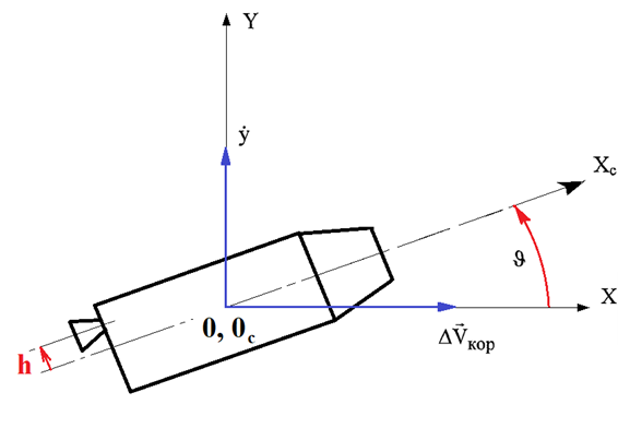
Figure 1 Spacecraft with linear movement of the PS in the inertial coordinate system.

Synthesis of spacecraft’s partially invariant stabilization system using an operating device with a linearly moving combustion chamber

Like the case of the stabilization system with the rotation of the operating device (OD), the conditions for the partial invariance of the center of mass tangential velocity relative to the disturbing moment and the disturbing force are the lack of feedback from the control actuator and the absence of an angular deviation error signal for the object.

We analyzed the physical reliability of the stabilization system, which was partially invariant with respect to the disturbing moment and force, for a spacecraft with linear movement of the PS. For the spacecraft type being considered, a system of equations describing the behavior of the closed-loop stabilization system is as follows:

{ s y ˙ C yϑ ϑ0h=F, 0 y ˙ + s 2 ϑ+ C ϑh h=M, W CM y ˙ + W yc ϑ+( K OC s K OD ). MathType@MTEF@5@5@+= feaagKart1ev2aaatCvAUfeBSjuyZL2yd9gzLbvyNv2CaerbuLwBLn hiov2DGi1BTfMBaeXatLxBI9gBaerbd9wDYLwzYbItLDharqqtubsr 4rNCHbGeaGqkY=wjYJH8sqFD0xXdHaVhbbf9v8qqaqFr0xc9pk0xbb a9q8WqFfeaY=biLkVcLq=JHqpepeea0=as0Fb9pgeaYRXxe9vr0=vr 0=vqpWqaaeaabiGaciaacaqabeaadaqaaqaaaOqaamaaceaabaqbae qabmqaaaqaaiaadohaceWG5bGbaiaacqGHsislcaWGdbWaaSbaaSqa aiaadMhacqaHrpGsaeqaaOGaeqy0dOKaeyOeI0IaaGimaiaadIgacq GH9aqpcaWGgbGaaiilaaqaaiaaicdaceWG5bGbaiaacqGHRaWkcaWG ZbWaaWbaaSqabeaacaaIYaaaaOGaeqy0dOKaey4kaSIaam4qamaaBa aaleaacqaHrpGscaWGObaabeaakiaadIgacqGH9aqpcaWGnbGaaiil aaqaaiaadEfadaWgaaWcbaGaam4qaiaad2eaaeqaaOGabmyEayaaca Gaey4kaSIaam4vamaaBaaaleaacaWG5bGaam4yaaqabaGccqaHrpGs cqGHRaWkdaqadaqaaiabgkHiTiaadUeadaWgaaWcbaGaam4taiaado eaaeqaaOGaeyOeI0YaaSaaaeaacaWGZbaabaGaam4samaaBaaaleaa caWGpbGaamiraaqabaaaaaGccaGLOaGaayzkaaGaaiOlaaaaaiaawU haaaaa@6939@ (1)

We used the same variable designations as in previous reports.31,33–35 We used a new type of OD in this system of equations, and thus, we introduced the linear displacement h of the operating device instead of the deviation angle δ. Instead of using coefficient С ϑh , MathType@MTEF@5@5@+= feaagKart1ev2aaatCvAUfeBSjuyZL2yd9gzLbvyNv2CaerbuLwBLn hiov2DGi1BTfMBaeXatLxBI9gBaerbd9wDYLwzYbItLDharqqr1ngB PrgifHhDYfgasaacH8YjY=vipgYlh9vqqj=hEeeu0xXdbba9frFj0= OqFfea0dXdd9vqai=hGuQ8kuc9pgc9q8qqaq=dir=f0=yqaiVgFr0x fr=xfr=xb9adbaqaaeGaciGaaiaabeqaamaabaabaaGcbaGaamyiem aaBaaaleaacqaHrpGscaWGObaabeaakiaacYcaaaa@3BC5@ the angular acceleration of the spacecraft was determined based on the linear movement of the OD. Instead of using coefficient, the angular acceleration of the spacecraft was determined based on the linear movement of the OD. Since the linear movement of the OD does not cause linear acceleration perpendicular to the X-axis of the spacecraft, the equation lacks a term proportional to the OD movement. The block diagram for the stabilization system under study is presented in Figure 2.

Figure 2 Block diagram of the spacecraft centre of the mass stabilization system with linear movement of PS (Nomenclature:   C_y_delta, С yδ ; MathType@MTEF@5@5@+= feaagKart1ev2aaatCvAUfeBSjuyZL2yd9gzLbvyNv2CaerbuLwBLn hiov2DGi1BTfMBaeXatLxBI9gBaerbd9wDYLwzYbItLDharqqr1ngB PrgifHhDYfgasaacH8YjY=vipgYlh9vqqj=hEeeu0xXdbba9frFj0= OqFfea0dXdd9vqai=hGuQ8kuc9pgc9q8qqaq=dir=f0=yqaiVgFr0x fr=xfr=xb9adbaqaaeGaciGaaiaabeqaamaabaabaaGcbaqcLbsaca WGHqWcdaWgaaqaaKqzadGaamyEaiabes7aKbWcbeaajugibiaacUda aaa@3E2F@ C_y_upsilon, С yϑ ; MathType@MTEF@5@5@+= feaagKart1ev2aaatCvAUfeBSjuyZL2yd9gzLbvyNv2CaerbuLwBLn hiov2DGi1BTfMBaeXatLxBI9gBaerbd9wDYLwzYbItLDharqqr1ngB PrgifHhDYfgasaacH8YjY=vipgYlh9vqqj=hEeeu0xXdbba9frFj0= OqFfea0dXdd9vqai=hGuQ8kuc9pgc9q8qqaq=dir=f0=yqaiVgFr0x fr=xfr=xb9adbaqaaeGaciGaaiaabeqaamaabaabaaGcbaqcLbsaca WGHqGcdaWgaaWcbaqcLbmacaWG5bGaeqy0dOealeqaaKqzGeGaai4o aaaa@3E3C@ C_upsilon_delta, С ϑh ; MathType@MTEF@5@5@+= feaagKart1ev2aaatCvAUfeBSjuyZL2yd9gzLbvyNv2CaerbuLwBLn hiov2DGi1BTfMBaeXatLxBI9gBaerbd9wDYLwzYbItLDharqqr1ngB PrgifHhDYfgasaacH8YjY=vipgYlh9vqqj=hEeeu0xXdbba9frFj0= OqFfea0dXdd9vqai=hGuQ8kuc9pgc9q8qqaq=dir=f0=yqaiVgFr0x fr=xfr=xb9adbaqaaeGaciGaaiaabeqaamaabaabaaGcbaqcLbsaca WGHqGcdaWgaaWcbaqcLbmacqaHrpGscaWGObaaleqaaKqzGeGaai4o aaaa@3E2B@ W_AS, W AS ; MathType@MTEF@5@5@+= feaagKart1ev2aaatCvAUfeBSjuyZL2yd9gzLbvyNv2CaerbuLwBLn hiov2DGi1BTfMBaeXatLxBI9gBaerbd9wDYLwzYbItLDharqqr1ngB PrgifHhDYfgasaacH8YjY=vipgYlh9vqqj=hEeeu0xXdbba9frFj0= OqFfea0dXdd9vqai=hGuQ8kuc9pgc9q8qqaq=dir=f0=yqaiVgFr0x fr=xfr=xb9adbaqaaeGaciGaaiaabeqaamaabaabaaGcbaqcLbsaca WGxbWcdaWgaaqaaKqzadGaamyqaiaadofaaSqabaqcLbsacaGG7aaa aa@3D5C@ W_CM, W CM ; MathType@MTEF@5@5@+= feaagKart1ev2aaatCvAUfeBSjuyZL2yd9gzLbvyNv2CaerbuLwBLn hiov2DGi1BTfMBaeXatLxBI9gBaerbd9wDYLwzYbItLDharqqr1ngB PrgifHhDYfgasaacH8YjY=vipgYlh9vqqj=hEeeu0xXdbba9frFj0= OqFfea0dXdd9vqai=hGuQ8kuc9pgc9q8qqaq=dir=f0=yqaiVgFr0x fr=xfr=xb9adbaqaaeGaciGaaiaabeqaamaabaabaaGcbaqcLbsaca WGxbqcfa4aaSbaaSqaaKqzadGaam4qaiaad2eaaSqabaqcLbsacaGG 7aaaaa@3DE6@ k_CA, k CA ; MathType@MTEF@5@5@+= feaagKart1ev2aaatCvAUfeBSjuyZL2yd9gzLbvyNv2CaerbuLwBLn hiov2DGi1BTfMBaeXatLxBI9gBaerbd9wDYLwzYbItLDharqqr1ngB PrgifHhDYfgasaacH8YjY=vipgYlh9vqqj=hEeeu0xXdbba9frFj0= OqFfea0dXdd9vqai=hGuQ8kuc9pgc9q8qqaq=dir=f0=yqaiVgFr0x fr=xfr=xb9adbaqaaeGaciGaaiaabeqaamaabaabaaGcbaqcLbsaca WGRbqcfa4aaSbaaSqaaKqzadGaam4qaiaadgeaaSqabaqcLbsacaGG 7aaaaa@3DEE@ k_FB, k FB ; MathType@MTEF@5@5@+= feaagKart1ev2aaatCvAUfeBSjuyZL2yd9gzLbvyNv2CaerbuLwBLn hiov2DGi1BTfMBaeXatLxBI9gBaerbd9wDYLwzYbItLDharqqr1ngB PrgifHhDYfgasaacH8YjY=vipgYlh9vqqj=hEeeu0xXdbba9frFj0= OqFfea0dXdd9vqai=hGuQ8kuc9pgc9q8qqaq=dir=f0=yqaiVgFr0x fr=xfr=xb9adbaqaaeGaciGaaiaabeqaamaabaabaaGcbaqcLbsaca WGRbqcfa4aaSbaaSqaaKqzadGaamOraiaadkeaaSqabaqcLbsacaGG 7aaaaa@3DF2@ y_dot, y ˙ ; MathType@MTEF@5@5@+= feaagKart1ev2aaatCvAUfeBSjuyZL2yd9gzLbvyNv2CaerbuLwBLn hiov2DGi1BTfMBaeXatLxBI9gBaerbd9wDYLwzYbItLDharqqr1ngB PrgifHhDYfgasaacH8YjY=vipgYlh9vqqj=hEeeu0xXdbba9frFj0= OqFfea0dXdd9vqai=hGuQ8kuc9pgc9q8qqaq=dir=f0=yqaiVgFr0x fr=xfr=xb9adbaqaaeGaciGaaiaabeqaamaabaabaaGcbaqcLbsace WG5bGbaiaacaGG7aaaaa@39F5@ Upsilon1, ϑ 1 ; MathType@MTEF@5@5@+= feaagKart1ev2aaatCvAUfeBSjuyZL2yd9gzLbvyNv2CaerbuLwBLn hiov2DGi1BTfMBaeXatLxBI9gBaerbd9wDYLwzYbItLDharqqr1ngB PrgifHhDYfgasaacH8YjY=vipgYlh9vqqj=hEeeu0xXdbba9frFj0= OqFfea0dXdd9vqai=hGuQ8kuc9pgc9q8qqaq=dir=f0=yqaiVgFr0x fr=xfr=xb9adbaqaaeGaciGaaiaabeqaamaabaabaaGcbaqcLbsacq aHrpGsjuaGdaWgaaqaaKqzadGaaGymaaqcfayabaqcLbsacaGG7aaa aa@3E4B@ Upsilon, ϑ MathType@MTEF@5@5@+= feaagKart1ev2aaatCvAUfeBSjuyZL2yd9gzLbvyNv2CaerbuLwBLn hiov2DGi1BTfMBaeXatLxBI9gBaerbd9wDYLwzYbItLDharqqr1ngB PrgifHhDYfgasaacH8YjY=vipgYlh9vqqj=hEeeu0xXdbba9frFj0= OqFfea0dXdd9vqai=hGuQ8kuc9pgc9q8qqaq=dir=f0=yqaiVgFr0x fr=xfr=xb9adbaqaaeGaciGaaiaabeqaamaabaabaaGcbaqcLbsacq aHrpGsaaa@39D7@ )

Invariance conditions with respect to disturbing influences are expressed as follows:

C yϑ ( K CA + 1 K OD s )=0, MathType@MTEF@5@5@+= feaagKart1ev2aaatCvAUfeBSjuyZL2yd9gzLbvyNv2CaerbuLwBLn hiov2DGi1BTfMBaeXatLxBI9gBaerbd9wDYLwzYbItLDharqqtubsr 4rNCHbGeaGqkY=wjYJH8sqFD0xXdHaVhbbf9v8qqaqFr0xc9pk0xbb a9q8WqFfeaY=biLkVcLq=JHqpepeea0=as0Fb9pgeaYRXxe9vr0=vr 0=vqpWqaaeaabiGaciaacaqabeaadaqaaqaaaOqaaiaadoeadaWgaa WcbaGaamyEaiabeg9akbqabaGcdaqadaqaaiaadUeadaWgaaWcbaGa am4qaiaadgeaaeqaaOGaey4kaSYaaSaaaeaacaaIXaaabaGaam4sam aaBaaaleaacaWGpbGaamiraaqabaaaaOGaam4CaaGaayjkaiaawMca aiabg2da9iaaicdacaGGSaaaaa@47A3@ (2)

s 2 ( K CA + 1 K CA s )+ C ϑh W OD =0. MathType@MTEF@5@5@+= feaagKart1ev2aaatCvAUfeBSjuyZL2yd9gzLbvyNv2CaerbuLwBLn hiov2DGi1BTfMBaeXatLxBI9gBaerbd9wDYLwzYbItLDharqqtubsr 4rNCHbGeaGqkY=wjYJH8sqFD0xXdHaVhbbf9v8qqaqFr0xc9pk0xbb a9q8WqFfeaY=biLkVcLq=JHqpepeea0=as0Fb9pgeaYRXxe9vr0=vr 0=vqpWqaaeaabiGaciaacaqabeaadaqaaqaaaOqaaiaacohadaahaa WcbeqaaiaaikdaaaGcdaqadaqaaiaadUeadaWgaaWcbaGaam4qaiaa dgeaaeqaaOGaey4kaSYaaSaaaeaacaaIXaaabaGaam4samaaBaaale aacaWGdbGaamyqaaqabaaaaOGaam4CaaGaayjkaiaawMcaaiabgUca RiaadoeadaWgaaWcbaGaeqy0dOKaamiAaaqabaGccaWGxbWaaSbaaS qaaiaad+eacaWGebaabeaakiabg2da9iaaicdacaGGUaaaaa@4D00@ (3)

From these equations, we obtain the following:

W OD =0, K CA = s K CA . MathType@MTEF@5@5@+= feaagKart1ev2aaatCvAUfeBSjuyZL2yd9gzLbvyNv2CaerbuLwBLn hiov2DGi1BTfMBaeXatLxBI9gBaerbd9wDYLwzYbItLDharqqtubsr 4rNCHbGeaGqkY=wjYJH8sqFD0xXdHaVhbbf9v8qqaqFr0xc9pk0xbb a9q8WqFfeaY=biLkVcLq=JHqpepeea0=as0Fb9pgeaYRXxe9vr0=vr 0=vqpWqaaeaabiGaciaacaqabeaadaqaaqaaaOqaaiaadEfadaWgaa WcbaGaam4taiaadseaaeqaaOGaeyypa0JaaGimaiaacYcacaWGlbWa aSbaaSqaaiaadoeacaWGbbaabeaakiabg2da9iabgkHiTmaalaaaba Gaam4CaaqaaiaadUeadaWgaaWcbaGaam4qaiaadgeaaeqaaaaakiaa c6caaaa@461E@ (4)

To physically realize an invariant system, the following condition must be met:30

Δ openloop 0, MathType@MTEF@5@5@+= feaagKart1ev2aaatCvAUfeBSjuyZL2yd9gzLbvyNv2CaerbuLwBLn hiov2DGi1BTfMBaeXatLxBI9gBaerbd9wDYLwzYbItLDharqqtubsr 4rNCHbGeaGqkY=wjYJH8sqFD0xXdHaVhbbf9v8qqaqFr0xc9pk0xbb a9q8WqFfeaY=biLkVcLq=JHqpepeea0=as0Fb9pgeaYRXxe9vr0=vr 0=vqpWqaaeaabiGaciaacaqabeaadaqaaqaaaOqaaiabfs5aenaaBa aaleaacaGGVbGaaiiCaiaacwgacaGGUbGaeyOeI0IaamiBaiaad+ga caWGVbGaamiCaaqabaGccqGHGjsUcaaIWaGaaiilaaaa@4574@ (5)

where Δ openloop MathType@MTEF@5@5@+= feaagKart1ev2aaatCvAUfeBSjuyZL2yd9gzLbvyNv2CaerbuLwBLn hiov2DGi1BTfMBaeXatLxBI9gBaerbd9wDYLwzYbItLDharqqtubsr 4rNCHbGeaGqkY=wjYJH8sqFD0xXdHaVhbbf9v8qqaqFr0xc9pk0xbb a9q8WqFfeaY=biLkVcLq=JHqpepeea0=as0Fb9pgeaYRXxe9vr0=vr 0=vqpWqaaeaabiGaciaacaqabeaadaqaaqaaaOqaaiabfs5aenaaBa aaleaacaGGVbGaaiiCaiaacwgacaGGUbGaeyOeI0IaamiBaiaad+ga caWGVbGaamiCaaqabaaaaa@4239@ -  the open system determinant.

Using Equation (1), Δ openloop MathType@MTEF@5@5@+= feaagKart1ev2aaatCvAUfeBSjuyZL2yd9gzLbvyNv2CaerbuLwBLn hiov2DGi1BTfMBaeXatLxBI9gBaerbd9wDYLwzYbItLDharqqtubsr 4rNCHbGeaGqkY=wjYJH8sqFD0xXdHaVhbbf9v8qqaqFr0xc9pk0xbb a9q8WqFfeaY=biLkVcLq=JHqpepeea0=as0Fb9pgeaYRXxe9vr0=vr 0=vqpWqaaeaabiGaciaacaqabeaadaqaaqaaaOqaaiabfs5aenaaBa aaleaacaGGVbGaaiiCaiaacwgacaGGUbGaeyOeI0IaamiBaiaad+ga caWGVbGaamiCaaqabaaaaa@4239@ can be expressed as follows:

Δ openloop =s[ s 2 ( K CA + 1 K CA s )+ C ϑh W OD ]. MathType@MTEF@5@5@+= feaagKart1ev2aaatCvAUfeBSjuyZL2yd9gzLbvyNv2CaerbuLwBLn hiov2DGi1BTfMBaeXatLxBI9gBaerbd9wDYLwzYbItLDharqqtubsr 4rNCHbGeaGqkY=wjYJH8sqFD0xXdHaVhbbf9v8qqaqFr0xc9pk0xbb a9q8WqFfeaY=biLkVcLq=JHqpepeea0=as0Fb9pgeaYRXxe9vr0=vr 0=vqpWqaaeaabiGaciaacaqabeaadaqaaqaaaOqaaiabfs5aenaaBa aaleaacaGGVbGaaiiCaiaacwgacaGGUbGaeyOeI0IaamiBaiaad+ga caWGVbGaamiCaaqabaGccqGH9aqpcaWGZbWaamWaaeaacaGGZbWaaW baaSqabeaacaaIYaaaaOWaaeWaaeaacaWGlbWaaSbaaSqaaiaadoea caWGbbaabeaakiabgUcaRmaalaaabaGaaGymaaqaaiaadUeadaWgaa WcbaGaam4qaiaadgeaaeqaaaaakiaadohaaiaawIcacaGLPaaacqGH RaWkcaWGdbWaaSbaaSqaaiabeg9akjaadIgaaeqaaOGaam4vamaaBa aaleaacaWGpbGaamiraaqabaaakiaawUfacaGLDbaacaGGUaaaaa@5949@ (6)

When conditions (2) and (3) are met, Equation (6) is identically zero. From this it follows that in this stabilization system, the absolute invariance is not simultaneously feasible for the moment M and force F. The physical explanation of the impossibility of the synthesis of an absolutely invariant system in the case under consideration can be understood from the analysis of the block diagram (Figure 2). It follows from this diagram that in contrast to the system with rotation of the OD,32,33–35 some distribution channels are absent even for one disturbing effect in a system with linear movement of the operating device. This is due to the lack of a link C yδ s MathType@MTEF@5@5@+= feaagKart1ev2aaatCvAUfeBSjuyZL2yd9gzLbvyNv2CaerbuLwBLn hiov2DGi1BTfMBaeXatLxBI9gBaerbd9wDYLwzYbItLDharqqtubsr 4rNCHbGeaGqkY=wjYJH8sqFD0xXdHaVhbbf9v8qqaqFr0xc9pk0xbb a9q8WqFfeaY=biLkVcLq=JHqpepeea0=as0Fb9pgeaYRXxe9vr0=vr 0=vqpWqaaeaabiGaciaacaqabeaadaqaaqaaaOqaamaalaaabaGaam 4qamaaBaaaleaacaWG5bGaeqiTdqgabeaaaOqaaiaadohaaaaaaa@3CD3@ .

We investigated whether it was possible to synthesize a system that is partially invariant with respect to the disturbing moment and force using an approach proposed previously.35 In this approach, the conditions of absolute invariance are replaced with the conditions of partial invariance to determine the physical feasibility of the system. Thus, we considered the fulfillment of conditions (2) and (3) with respect to the disturbances themselves and not their derivatives. In this case, the invariance conditions (2) and (3) are as follows: C yϑ K CA ; C ϑh W OD MathType@MTEF@5@5@+= feaagKart1ev2aaatCvAUfeBSjuyZL2yd9gzLbvyNv2CaerbuLwBLn hiov2DGi1BTfMBaeXatLxBI9gBaerbd9wDYLwzYbItLDharqqtubsr 4rNCHbGeaGqkY=wjYJH8sqFD0xXdHaVhbbf9v8qqaqFr0xc9pk0xbb a9q8WqFfeaY=biLkVcLq=JHqpepeea0=as0Fb9pgeaYRXxe9vr0=vr 0=vqpWqaaeaabiGaciaacaqabeaadaqaaqaaaOqaaiaadoeadaWgaa WcbaGaamyEaiabeg9akbqabaGccaWGlbWaaSbaaSqaaiaadoeacaWG bbaabeaakiaacUdacaWGdbWaaSbaaSqaaiabeg9akjaadIgaaeqaaO Gaam4vamaaBaaaleaacaWGpbGaamiraaqabaaaaa@4559@ .

Thus, the partial invariance conditions are as follows:

K CA =0, MathType@MTEF@5@5@+= feaagKart1ev2aaatCvAUfeBSjuyZL2yd9gzLbvyNv2CaerbuLwBLn hiov2DGi1BTfMBaeXatLxBI9gBaerbd9wDYLwzYbItLDharqqtubsr 4rNCHbGeaGqkY=wjYJH8sqFD0xXdHaVhbbf9v8qqaqFr0xc9pk0xbb a9q8WqFfeaY=biLkVcLq=JHqpepeea0=as0Fb9pgeaYRXxe9vr0=vr 0=vqpWqaaeaabiGaciaacaqabeaadaqaaqaaaOqaaiaadUeadaWgaa WcbaGaam4qaiaadgeaaeqaaOGaeyypa0JaaGimaiaacYcaaaa@3D2E@ (7)

W OD| s0 = k ϑ =0. MathType@MTEF@5@5@+= feaagKart1ev2aaatCvAUfeBSjuyZL2yd9gzLbvyNv2CaerbuLwBLn hiov2DGi1BTfMBaeXatLxBI9gBaerbd9wDYLwzYbItLDharqqtubsr 4rNCHbGeaGqkY=wjYJH8sqFD0xXdHaVhbbf9v8qqaqFr0xc9pk0xbb a9q8WqFfeaY=biLkVcLq=JHqpepeea0=as0Fb9pgeaYRXxe9vr0=vr 0=vqpWqaaeaabiGaciaacaqabeaadaqaaqaaaOqaaiaadEfadaWgaa WcbaGaam4taiaadseadaabbaqaaiaadohacqGHsgIRcaaIWaaacaGL hWoaaeqaaOGaeyypa0Jaam4AamaaBaaaleaacqaHrpGsaeqaaOGaey ypa0JaaGimaiaac6caaaa@4652@ (8)

As in the case of the stabilization system with rotation of the OD, the conditions for partial invariance of the centre of mass tangential velocity relative to the disturbing moment and force are the lack of feedback from the control actuator and the absence of an angular deviation error signal for the object.

The stability of such a system is studied in more detail. The characteristic equation of the system accounting for the invariance conditions (7) and (8) is as follows (excluding dynamic delay of the stabilization controller):

1 K CA s 4 +0 s 3 + C ϑh k ϑ ˙ s 2 +0s+ C yh C ϑh k y ˙ =0. MathType@MTEF@5@5@+= feaagKart1ev2aaatCvAUfeBSjuyZL2yd9gzLbvyNv2CaerbuLwBLn hiov2DGi1BTfMBaeXatLxBI9gBaerbd9wDYLwzYbItLDharqqtubsr 4rNCHbGeaGqkY=wjYJH8sqFD0xXdHaVhbbf9v8qqaqFr0xc9pk0xbb a9q8WqFfeaY=biLkVcLq=JHqpepeea0=as0Fb9pgeaYRXxe9vr0=vr 0=vqpWqaaeaabiGaciaacaqabeaadaqaaqaaaOqaamaalaaabaGaaG ymaaqaaiaadUeadaWgaaWcbaGaam4qaiaadgeaaeqaaaaakiaadoha daahaaWcbeqaaiaaisdaaaGccqGHRaWkcaaIWaGaam4CamaaCaaale qabaGaaG4maaaakiabgUcaRiaadoeadaWgaaWcbaGaeqy0dOKaamiA aaqabaGccaWGRbWaaSbaaSqaaiqbeg9akzaacaaabeaakiaadohada ahaaWcbeqaaiaaikdaaaGccqGHRaWkcaaIWaGaam4CaiabgUcaRiaa doeadaWgaaWcbaGaamyEaiaadIgaaeqaaOGaam4qamaaBaaaleaacq aHrpGscaWGObaabeaakiaadUgadaWgaaWcbaGabmyEayaacaaabeaa kiabg2da9iaaicdacaGGUaaaaa@58C6@ (9)

It follows from this characteristic equation that this stabilization system is unstable because there are zero coefficients in the 3rd and the 1st degrees s. To provide stability, it is necessary to introduce second derivatives of the object deviation angle k ϑ ¨ s 2 MathType@MTEF@5@5@+= feaagKart1ev2aaatCvAUfeBSjuyZL2yd9gzLbvyNv2CaerbuLwBLn hiov2DGi1BTfMBaeXatLxBI9gBaerbd9wDYLwzYbItLDharqqtubsr 4rNCHbGeaGqkY=wjYJH8sqFD0xXdHaVhbbf9v8qqaqFr0xc9pk0xbb a9q8WqFfeaY=biLkVcLq=JHqpepeea0=as0Fb9pgeaYRXxe9vr0=vr 0=vqpWqaaeaabiGaciaacaqabeaadaqaaqaaaOqaaiaadUgadaWgaa WcbaGafqy0dOKbamaaaeqaaOGaam4CamaaCaaaleqabaGaaGOmaaaa aaa@3CE3@ and the centre of mass drift velocity derivative k y ¨ s MathType@MTEF@5@5@+= feaagKart1ev2aaatCvAUfeBSjuyZL2yd9gzLbvyNv2CaerbuLwBLn hiov2DGi1BTfMBaeXatLxBI9gBaerbd9wDYLwzYbItLDharqqtubsr 4rNCHbGeaGqkY=wjYJH8sqFD0xXdHaVhbbf9v8qqaqFr0xc9pk0xbb a9q8WqFfeaY=biLkVcLq=JHqpepeea0=as0Fb9pgeaYRXxe9vr0=vr 0=vqpWqaaeaabiGaciaacaqabeaadaqaaqaaaOqaaiaadUgadaWgaa WcbaGabmyEayaadaaabeaakiaadohaaaa@3B50@ into the control system. In this case, the characteristic equation is as follows:

1 K CA s 4 + C ϑh k ϑ ¨ s 3 + C ϑh k ϑ ˙ s 2 + C yh C ϑh k y ¨ s+ C yh C ϑh k y ˙ =0. MathType@MTEF@5@5@+= feaagKart1ev2aaatCvAUfeBSjuyZL2yd9gzLbvyNv2CaerbuLwBLn hiov2DGi1BTfMBaeXatLxBI9gBaerbd9wDYLwzYbItLDharqqtubsr 4rNCHbGeaGqkY=wjYJH8sqFD0xXdHaVhbbf9v8qqaqFr0xc9pk0xbb a9q8WqFfeaY=biLkVcLq=JHqpepeea0=as0Fb9pgeaYRXxe9vr0=vr 0=vqpWqaaeaabiGaciaacaqabeaadaqaaqaaaOqaamaalaaabaGaaG ymaaqaaiaadUeadaWgaaWcbaGaam4qaiaadgeaaeqaaaaakiaadoha daahaaWcbeqaaiaaisdaaaGccqGHRaWkcaWGdbWaaSbaaSqaaiabeg 9akjaadIgaaeqaaOGaam4AamaaBaaaleaacuaHrpGsgaWaaaqabaGc caWGZbWaaWbaaSqabeaacaaIZaaaaOGaey4kaSIaam4qamaaBaaale aacqaHrpGscaWGObaabeaakiaadUgadaWgaaWcbaGafqy0dOKbaiaa aeqaaOGaam4CamaaCaaaleqabaGaaGOmaaaakiabgUcaRiaadoeada WgaaWcbaGaamyEaiaadIgaaeqaaOGaam4qamaaBaaaleaacqaHrpGs caWGObaabeaakiaadUgadaWgaaWcbaGabmyEayaadaaabeaakiaado hacqGHRaWkcaWGdbWaaSbaaSqaaiaadMhacaWGObaabeaakiaadoea daWgaaWcbaGaeqy0dOKaamiAaaqabaGccaWGRbWaaSbaaSqaaiqadM hagaGaaaqabaGccqGH9aqpcaaIWaGaaiOlaaaa@6667@ (10)

As in the case of an invariant stabilization system, this system is “rough”,32,35 since the fulfillment of the invariance conditions ( K CA =0; k ϑ =0 ) MathType@MTEF@5@5@+= feaagKart1ev2aaatCvAUfeBSjuyZL2yd9gzLbvyNv2CaerbuLwBLn hiov2DGi1BTfMBaeXatLxBI9gBaerbd9wDYLwzYbItLDharqqtubsr 4rNCHbGeaGqkY=wjYJH8sqFD0xXdHaVhbbf9v8qqaqFr0xc9pk0xbb a9q8WqFfeaY=biLkVcLq=JHqpepeea0=as0Fb9pgeaYRXxe9vr0=vr 0=vqpWqaaeaabiGaciaacaqabeaadaqaaqaaaOqaamaabmaabaGaam 4samaaBaaaleaacaWGdbGaamyqaaqabaGccqGH9aqpcaaIWaGaai4o aiaadUgadaWgaaWcbaGaeqy0dOeabeaakiabg2da9iaaicdaaiaawI cacaGLPaaaaaa@4354@ does not lead to a decrease in the order of the characteristic equation. Consequently, enough degree of stability of the system can be provided by selecting the parameters for the control action. The block diagram of the stabilization system with linear movement of the OD corresponding to Equation (10) is presented in Figure 3.
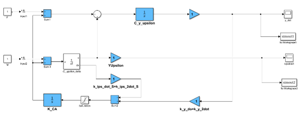
Figure 3 Block diagram of a partially invariant spacecraft centre of the mass stabilization system with linear movement of OD (Nomenclature:   C_y_delta, С yδ ; MathType@MTEF@5@5@+= feaagKart1ev2aaatCvAUfeBSjuyZL2yd9gzLbvyNv2CaerbuLwBLn hiov2DGi1BTfMBaeXatLxBI9gBaerbd9wDYLwzYbItLDharqqr1ngB PrgifHhDYfgasaacH8YjY=vipgYlh9vqqj=hEeeu0xXdbba9frFj0= OqFfea0dXdd9vqai=hGuQ8kuc9pgc9q8qqaq=dir=f0=yqaiVgFr0x fr=xfr=xb9adbaqaaeGaciGaaiaabeqaamaabaabaaGcbaqcLbsaca WGHqGcdaWgaaWcbaqcLbmacaWG5bGaeqiTdqgaleqaaKqzGeGaai4o aaaa@3E39@ C_y_upsilon, С yϑ ; MathType@MTEF@5@5@+= feaagKart1ev2aaatCvAUfeBSjuyZL2yd9gzLbvyNv2CaerbuLwBLn hiov2DGi1BTfMBaeXatLxBI9gBaerbd9wDYLwzYbItLDharqqr1ngB PrgifHhDYfgasaacH8YjY=vipgYlh9vqqj=hEeeu0xXdbba9frFj0= OqFfea0dXdd9vqai=hGuQ8kuc9pgc9q8qqaq=dir=f0=yqaiVgFr0x fr=xfr=xb9adbaqaaeGaciGaaiaabeqaamaabaabaaGcbaqcLbsaca WGHqGcdaWgaaWcbaqcLbmacaWG5bGaeqy0dOealeqaaKqzGeGaai4o aaaa@3E3C@ C_upsilon_delta, С ϑh ; MathType@MTEF@5@5@+= feaagKart1ev2aaatCvAUfeBSjuyZL2yd9gzLbvyNv2CaerbuLwBLn hiov2DGi1BTfMBaeXatLxBI9gBaerbd9wDYLwzYbItLDharqqr1ngB PrgifHhDYfgasaacH8YjY=vipgYlh9vqqj=hEeeu0xXdbba9frFj0= OqFfea0dXdd9vqai=hGuQ8kuc9pgc9q8qqaq=dir=f0=yqaiVgFr0x fr=xfr=xb9adbaqaaeGaciGaaiaabeqaamaabaabaaGcbaqcLbsaca WGHqGcdaWgaaWcbaqcLbmacqaHrpGscaWGObaaleqaaKqzGeGaai4o aaaa@3E2B@ k_ips_dot_S+k_ips_2dot_S, k ϑ ˙ / S+ k ϑ ¨ ; MathType@MTEF@5@5@+= feaagKart1ev2aaatCvAUfeBSjuyZL2yd9gzLbvyNv2CaerbuLwBLn hiov2DGi1BTfMBaeXatLxBI9gBaerbd9wDYLwzYbItLDharqqr1ngB PrgifHhDYfgasaacH8YjY=vipgYlh9vqqj=hEeeu0xXdbba9frFj0= OqFfea0dXdd9vqai=hGuQ8kuc9pgc9q8qqaq=dir=f0=yqaiVgFr0x fr=xfr=xb9adbaqaaeGaciGaaiaabeqaamaabaabaaGcbaqcLbsaca WGRbqcfa4aaSbaaSqaamaalyaabaqcLbmacuaHrpGsgaGaaaWcbaqc LbmacaWGtbGaey4kaSIaam4AaSWaaSbaaWqaaKqzadGafqy0dOKbam aaaWqabaaaaaWcbeaajugibiaacUdaaaa@452E@ k_y_dot+k_y_2dot, k y ˙ + k y ¨ ; MathType@MTEF@5@5@+= feaagKart1ev2aaatCvAUfeBSjuyZL2yd9gzLbvyNv2CaerbuLwBLn hiov2DGi1BTfMBaeXatLxBI9gBaerbd9wDYLwzYbItLDharqqr1ngB PrgifHhDYfgasaacH8YjY=vipgYlh9vqqj=hEeeu0xXdbba9frFj0= OqFfea0dXdd9vqai=hGuQ8kuc9pgc9q8qqaq=dir=f0=yqaiVgFr0x fr=xfr=xb9adbaqaaeGaciGaaiaabeqaamaabaabaaGcbaqcLbsaca WGRbqcfa4aaSbaaSqaaKqzadGabmyEayaacaaaleqaaKqzGeGaey4k aSIaam4AaKqbaoaaBaaaleaajugWaiqadMhagaWaaaWcbeaajugibi aacUdaaaa@42C3@ k_CA, k CA ; MathType@MTEF@5@5@+= feaagKart1ev2aaatCvAUfeBSjuyZL2yd9gzLbvyNv2CaerbuLwBLn hiov2DGi1BTfMBaeXatLxBI9gBaerbd9wDYLwzYbItLDharqqr1ngB PrgifHhDYfgasaacH8YjY=vipgYlh9vqqj=hEeeu0xXdbba9frFj0= OqFfea0dXdd9vqai=hGuQ8kuc9pgc9q8qqaq=dir=f0=yqaiVgFr0x fr=xfr=xb9adbaqaaeGaciGaaiaabeqaamaabaabaaGcbaqcLbsaca WGRbqcfa4aaSbaaSqaaKqzadGaam4qaiaadgeaaSqabaqcLbsacaGG 7aaaaa@3DEE@ k_FB, k FB ; MathType@MTEF@5@5@+= feaagKart1ev2aaatCvAUfeBSjuyZL2yd9gzLbvyNv2CaerbuLwBLn hiov2DGi1BTfMBaeXatLxBI9gBaerbd9wDYLwzYbItLDharqqr1ngB PrgifHhDYfgasaacH8YjY=vipgYlh9vqqj=hEeeu0xXdbba9frFj0= OqFfea0dXdd9vqai=hGuQ8kuc9pgc9q8qqaq=dir=f0=yqaiVgFr0x fr=xfr=xb9adbaqaaeGaciGaaiaabeqaamaabaabaaGcbaqcLbsaca WGRbqcfa4aaSbaaSqaaKqzadGaamOraiaadkeaaSqabaqcLbsacaGG 7aaaaa@3DF2@ y_dot, y ˙ ; MathType@MTEF@5@5@+= feaagKart1ev2aaatCvAUfeBSjuyZL2yd9gzLbvyNv2CaerbuLwBLn hiov2DGi1BTfMBaeXatLxBI9gBaerbd9wDYLwzYbItLDharqqr1ngB PrgifHhDYfgasaacH8YjY=vipgYlh9vqqj=hEeeu0xXdbba9frFj0= OqFfea0dXdd9vqai=hGuQ8kuc9pgc9q8qqaq=dir=f0=yqaiVgFr0x fr=xfr=xb9adbaqaaeGaciGaaiaabeqaamaabaabaaGcbaqcLbsace WG5bGbaiaacaGG7aaaaa@39F5@ Upsilon1, ϑ 1 ; MathType@MTEF@5@5@+= feaagKart1ev2aaatCvAUfeBSjuyZL2yd9gzLbvyNv2CaerbuLwBLn hiov2DGi1BTfMBaeXatLxBI9gBaerbd9wDYLwzYbItLDharqqr1ngB PrgifHhDYfgasaacH8YjY=vipgYlh9vqqj=hEeeu0xXdbba9frFj0= OqFfea0dXdd9vqai=hGuQ8kuc9pgc9q8qqaq=dir=f0=yqaiVgFr0x fr=xfr=xb9adbaqaaeGaciGaaiaabeqaamaabaabaaGcbaqcLbsacq aHrpGsjuaGdaWgaaqaaKqzadGaaGymaaqcfayabaqcLbsacaGG7aaa aa@3E4B@ Upsilon, ϑ MathType@MTEF@5@5@+= feaagKart1ev2aaatCvAUfeBSjuyZL2yd9gzLbvyNv2CaerbuLwBLn hiov2DGi1BTfMBaeXatLxBI9gBaerbd9wDYLwzYbItLDharqqr1ngB PrgifHhDYfgasaacH8YjY=vipgYlh9vqqj=hEeeu0xXdbba9frFj0= OqFfea0dXdd9vqai=hGuQ8kuc9pgc9q8qqaq=dir=f0=yqaiVgFr0x fr=xfr=xb9adbaqaaeGaciGaaiaabeqaamaabaabaaGcbaqcLbsacq aHrpGsaaa@39D7@ ).

Modeling transition processes in partially invariant spacecraft center of the mass motion stabilization system with linear movement of the operating device

To compare the accuracy of the spacecraft’s transverse velocity stabilization from the standard and invariant control algorithms in the stabilization system with linear movement of the PS, we constructed a mathematical model. The modeling was performed in a similar manner to the modeling of the stabilization system with the rotation of PS.31-35 Accounting for the above changes, the structural schemes of the partially invariant and typical stabilization systems used in the mathematical modeling31,35 are subject to corresponding transformations. In these diagrams, the disturbing moment is provided by the equivalent linear movement of the h M MathType@MTEF@5@5@+= feaagKart1ev2aaatCvAUfeBSjuyZL2yd9gzLbvyNv2CaerbuLwBLn hiov2DGi1BTfMBaeXatLxBI9gBaerbd9wDYLwzYbItLDharqqtubsr 4rNCHbGeaGqkY=wjYJH8sqFD0xXdHaVhbbf9v8qqaqFr0xc9pk0xbb a9q8WqFfeaY=biLkVcLq=JHqpepeea0=as0Fb9pgeaYRXxe9vr0=vr 0=vqpWqaaeaabiGaciaacaqabeaadaqaaqaaaOqaaiaadIgadaWgaa WcbaGaamytaaqabaaaaa@3A15@ , and the disturbing force by the equivalent angle of deviation of spacecraft’s X-axis ϑ F MathType@MTEF@5@5@+= feaagKart1ev2aaatCvAUfeBSjuyZL2yd9gzLbvyNv2CaerbuLwBLn hiov2DGi1BTfMBaeXatLxBI9gBaerbd9wDYLwzYbItLDharqqtubsr 4rNCHbGeaGqkY=wjYJH8sqFD0xXdHaVhbbf9v8qqaqFr0xc9pk0xbb a9q8WqFfeaY=biLkVcLq=JHqpepeea0=as0Fb9pgeaYRXxe9vr0=vr 0=vqpWqaaeaabiGaciaacaqabeaadaqaaqaaaOqaaiabeg9aknaaBa aaleaacaWGgbaabeaaaaa@3AC9@ .

For the modeling, we used real parameters of the stabilization system of the simulated automatic interplanetary station discussed previously36 corresponding to the third and final correction section (Table 1) as parameters for the control object, servo controller, and disturbance and stabilization controller (for a standard system). The parameters for the stabilization controller for the invariant system (Table 2) were chosen based on the method described previously.36 The selection of these parameters for the spacecraft under consideration is described elsewhere.37 The values of these parameters for the invariant and standard stabilization systems obtained during the modeling are presented in Table 3 (Figures 4-6).

Controlled object

C ϑh =0.246 grad mm s 2 MathType@MTEF@5@5@+= feaagKart1ev2aaatCvAUfeBSjuyZL2yd9gzLbvyNv2CaerbuLwBLn hiov2DGi1BTfMBaeXatLxBI9gBaerbd9wDYLwzYbItLDharqqtubsr 4rNCHbGeaGqkY=wjYJH8sqFD0xXdHaVhbbf9v8qqaqFr0xc9pk0xbb a9q8WqFfeaY=biLkVcLq=JHqpepeea0=as0Fb9pgeaYRXxe9vr0=vr 0=vqpWqaaeaabiGaciaacaqabeaadaqaaqaaaOqaaiaadoeadaWgaa WcbaGaeqy0dOKaamiAaaqabaGccqGH9aqpcaaIWaGaaiOlaiaaikda caaI0aGaaGOnamaalaaabaGaam4zaiaadkhacaWGHbGaamizaaqaai aad2gacaWGTbGaeyyXICTaam4CamaaCaaaleqabaGaaGOmaaaaaaaa aa@4A3A@
C yϑ =0.072 m grad s 2 MathType@MTEF@5@5@+= feaagKart1ev2aaatCvAUfeBSjuyZL2yd9gzLbvyNv2CaerbuLwBLn hiov2DGi1BTfMBaeXatLxBI9gBaerbd9wDYLwzYbItLDharqqtubsr 4rNCHbGeaGqkY=wjYJH8sqFD0xXdHaVhbbf9v8qqaqFr0xc9pk0xbb a9q8WqFfeaY=biLkVcLq=JHqpepeea0=as0Fb9pgeaYRXxe9vr0=vr 0=vqpWqaaeaabiGaciaacaqabeaadaqaaqaaaOqaaiaadoeadaWgaa WcbaGaamyEaiabeg9akbqabaGccqGH9aqpcaaIWaGaaiOlaiaaicda caaI3aGaaGOmamaalaaabaGaamyBaaqaaiaadEgacaWGYbGaamyyai aadsgacqGHflY1caWGZbWaaWbaaSqabeaacaaIYaaaaaaaaaa@4956@

Servo control

K CA =5 mm smA , K OD =5 V mm , K C =5 mA V MathType@MTEF@5@5@+= feaagKart1ev2aaatCvAUfeBSjuyZL2yd9gzLbvyNv2CaerbuLwBLn hiov2DGi1BTfMBaeXatLxBI9gBaerbd9wDYLwzYbItLDharqqtubsr 4rNCHbGeaGqkY=wjYJH8sqFD0xXdHaVhbbf9v8qqaqFr0xc9pk0xbb a9q8WqFfeaY=biLkVcLq=JHqpepeea0=as0Fb9pgeaYRXxe9vr0=vr 0=vqpWqaaeaabiGaciaacaqabeaadaqaaqaaaOqaaiaadUeadaWgaa WcbaGaam4qaiaadgeaaeqaaOGaeyypa0JaaGynamaalaaabaGaamyB aiaad2gaaeaacaWGZbGaeyyXICTaamyBaiaadgeaaaGaaiilaiaadU eadaWgaaWcbaGaam4taiaadseaaeqaaOGaeyypa0JaaGynamaalaaa baGaamOvaaqaaiaad2gacaWGTbaaaiaacYcacaWGlbWaaSbaaSqaai aadoeaaeqaaOGaeyypa0JaaGynamaalaaabaGaamyBaiaadgeaaeaa caWGwbaaaaaa@523E@
T C =0.01s, I H =25mA, I 0 =3mA, h max MathType@MTEF@5@5@+= feaagKart1ev2aaatCvAUfeBSjuyZL2yd9gzLbvyNv2CaerbuLwBLn hiov2DGi1BTfMBaeXatLxBI9gBaerbd9wDYLwzYbItLDharqqtubsr 4rNCHbGeaGqkY=wjYJH8sqFD0xXdHaVhbbf9v8qqaqFr0xc9pk0xbb a9q8WqFfeaY=biLkVcLq=JHqpepeea0=as0Fb9pgeaYRXxe9vr0=vr 0=vqpWqaaeaabiGaciaacaqabeaadaqaaqaaaOqaaiaadsfadaWgaa WcbaGaam4qaaqabaGccqGH9aqpcaaIWaGaaiOlaiaaicdacaaIXaGa am4CaiaacYcacaWGjbWaaSbaaSqaaiaadIeaaeqaaOGaeyypa0JaaG OmaiaaiwdacaWGTbGaamyqaiaacYcacaWGjbWaaSbaaSqaaiaaicda aeqaaOGaeyypa0JaaG4maiaad2gacaWGbbGaaiilaiaadIgadaWgaa WcbaGaciyBaiaacggacaGG4baabeaaaaa@5020@

Stabilization controller

Disturbing effects

  k ϑ ˙ =10, k ϑ =5 V grad MathType@MTEF@5@5@+= feaagKart1ev2aaatCvAUfeBSjuyZL2yd9gzLbvyNv2CaerbuLwBLn hiov2DGi1BTfMBaeXatLxBI9gBaerbd9wDYLwzYbItLDharqqtubsr 4rNCHbGeaGqkY=wjYJH8sqFD0xXdHaVhbbf9v8qqaqFr0xc9pk0xbb a9q8WqFfeaY=biLkVcLq=JHqpepeea0=as0Fb9pgeaYRXxe9vr0=vr 0=vqpWqaaeaabiGaciaacaqabeaadaqaaqaaaOqaaiaadUgadaWgaa WcbaGafqy0dOKbaiaaaeqaaOGaeyypa0JaaGymaiaaicdacaGGSaGa am4AamaaBaaaleaacqaHrpGsaeqaaOGaeyypa0JaaGynamaalaaaba GaamOvaaqaaiaadEgacaWGYbGaamyyaiaadsgaaaaaaa@475C@
k y =3 V m , k y ˙ =60 V.s m MathType@MTEF@5@5@+= feaagKart1ev2aaatCvAUfeBSjuyZL2yd9gzLbvyNv2CaerbuLwBLn hiov2DGi1BTfMBaeXatLxBI9gBaerbd9wDYLwzYbItLDharqqtubsr 4rNCHbGeaGqkY=wjYJH8sqFD0xXdHaVhbbf9v8qqaqFr0xc9pk0xbb a9q8WqFfeaY=biLkVcLq=JHqpepeea0=as0Fb9pgeaYRXxe9vr0=vr 0=vqpWqaaeaabiGaciaacaqabeaadaqaaqaaaOqaaiaadUgadaWgaa WcbaGaamyEaaqabaGccqGH9aqpcaaIZaWaaSaaaeaacaWGwbaabaGa amyBaaaacaGGSaGaam4AamaaBaaaleaaceWG5bGbaiaaaeqaaOGaey ypa0JaaGOnaiaaicdadaWcaaqaaiaadAfacaGGUaGaam4Caaqaaiaa d2gaaaaaaa@46D2@

m h M H =13mm, m ϑ F H =0.2grad MathType@MTEF@5@5@+= feaagKart1ev2aaatCvAUfeBSjuyZL2yd9gzLbvyNv2CaerbuLwBLn hiov2DGi1BTfMBaeXatLxBI9gBaerbd9wDYLwzYbItLDharqqtubsr 4rNCHbGeaGqkY=MjYJH8sqFD0xXdHaVhbbf9v8qqaqFr0xc9pk0xbb a9q8WqFfeaY=biLkVcLq=JHqpepeea0=as0Fb9pgeaYRXxe9vr0=vr 0=vqpWqaaeaabiGaciaacaqabeaadaqaaqaaaOqaaiaad2gadaqhaa WcbaGaamiAamaaBaaameaacaWGnbaabeaaaSqaaiaadIeaaaGccqGH 9aqpcaaIXaGaaG4maiaad2gacaWGTbGaaiilaiaad2gadaqhaaWcba Gaeqy0dO0aaSbaaWqaaiaadAeaaeqaaaWcbaGaamisaaaakiabg2da 9iaaicdacaGGUaGaaGOmaiaadEgacaWGYbGaamyyaiaadsgaaaa@4CAB@
σ h M =1mm, σ ϑ F =0.1grad MathType@MTEF@5@5@+= feaagKart1ev2aaatCvAUfeBSjuyZL2yd9gzLbvyNv2CaerbuLwBLn hiov2DGi1BTfMBaeXatLxBI9gBaerbd9wDYLwzYbItLDharqqtubsr 4rNCHbGeaGqkY=wjYJH8sqFD0xXdHaVhbbf9v8qqaqFr0xc9pk0xbb a9q8WqFfeaY=biLkVcLq=JHqpepeea0=as0Fb9pgeaYRXxe9vr0=vr 0=vqpWqaaeaabiGaciaacaqabeaadaqaaqaaaOqaaiabeo8aZnaaBa aaleaacaWGObWaaSbaaWqaaiaad2eaaeqaaaWcbeaakiabg2da9iaa igdacaWGTbGaamyBaiaacYcacqaHdpWCdaWgaaWcbaGaeqy0dO0aaS baaWqaaiaadAeaaeqaaaWcbeaakiabg2da9iaaicdacaGGUaGaaGym aiaadEgacaWGYbGaamyyaiaadsgaaaa@4BF2@

Table 1 Parameters of the stabilization system for the modeled spacecraft36

Stabilization controller

k ϑ ˙ =4.1, k ϑ ¨ =0.7s, k y ˙ =40 Vs m , k y ¨ = V s 2 m MathType@MTEF@5@5@+= feaagKart1ev2aaatCvAUfeBSjuyZL2yd9gzLbvyNv2CaerbuLwBLn hiov2DGi1BTfMBaeXatLxBI9gBaerbd9wDYLwzYbItLDharqqtubsr 4rNCHbGeaGqkY=wjYJH8sqFD0xXdHaVhbbf9v8qqaqFr0xc9pk0xbb a9q8WqFfeaY=biLkVcLq=JHqpepeea0=as0Fb9pgeaYRXxe9vr0=vr 0=vqpWqaaeaabiGaciaacaqabeaadaqaaqaaaOqaaiaadUgadaWgaa WcbaGafqy0dOKbaiaaaeqaaOGaeyypa0JaaGinaiaac6cacaaIXaGa aiilaiaadUgadaWgaaWcbaGafqy0dOKbamaaaeqaaOGaeyypa0JaaG imaiaac6cacaaI3aGaam4CaiaacYcacaWGRbWaaSbaaSqaaiqadMha gaGaaaqabaGccqGH9aqpcaaI0aGaaGimamaalaaabaGaamOvaiabgw SixlaadohaaeaacaWGTbaaaiaacYcacaWGRbWaaSbaaSqaaiqadMha gaWaaaqabaGccqGH9aqpdaWcaaqaaiaadAfacqGHflY1caWGZbWaaW baaSqabeaacaaIYaaaaaGcbaGaamyBaaaaaaa@5A55@

Table 2 Parameters of the stabilization controller of a partially invariant system


m m s y ˙ max MathType@MTEF@5@5@+= feaagKart1ev2aaatCvAUfeBSjuyZL2yd9gzLbvyNv2CaerbuLwBLn hiov2DGi1BTfMBaeXatLxBI9gBaerbd9wDYLwzYbItLDharqqtubsr 4rNCHbGeaGqkY=wjYJH8sqFD0xXdHaVhbbf9v8qqaqFr0xc9pk0xbb a9q8WqFfeaY=biLkVcLq=JHqpepeea0=as0Fb9pgeaYRXxe9vr0=vr 0=vqpWqaaeaabiGaciaacaqabeaadaqaaqaaaOqaaiaad2gadaWcaa qaaiaad2gaaeaacaWGZbWaaSbaaSqaaiqadMhagaGaamaaBaaameaa ciGGTbGaaiyyaiaacIhaaeqaaaWcbeaaaaaaaa@3F55@

σ m s y ˙ max MathType@MTEF@5@5@+= feaagKart1ev2aaatCvAUfeBSjuyZL2yd9gzLbvyNv2CaerbuLwBLn hiov2DGi1BTfMBaeXatLxBI9gBaerbd9wDYLwzYbItLDharqqtubsr 4rNCHbGeaGqkY=wjYJH8sqFD0xXdHaVhbbf9v8qqaqFr0xc9pk0xbb a9q8WqFfeaY=biLkVcLq=JHqpepeea0=as0Fb9pgeaYRXxe9vr0=vr 0=vqpWqaaeaabiGaciaacaqabeaadaqaaqaaaOqaaiabeo8aZnaala aabaGaamyBaaqaaiaadohadaWgaaWcbaGabmyEayaacaWaaSbaaWqa aiGac2gacaGGHbGaaiiEaaqabaaaleqaaaaaaaa@4026@

y m s max MathType@MTEF@5@5@+= feaagKart1ev2aaatCvAUfeBSjuyZL2yd9gzLbvyNv2CaerbuLwBLn hiov2DGi1BTfMBaeXatLxBI9gBaerbd9wDYLwzYbItLDharqqtubsr 4rNCHbGeaGqkY=wjYJH8sqFD0xXdHaVhbbf9v8qqaqFr0xc9pk0xbb a9q8WqFfeaY=biLkVcLq=JHqpepeea0=as0Fb9pgeaYRXxe9vr0=vr 0=vqpWqaaeaabiGaciaacaqabeaadaqaaqaaaOqaaiaadMhadaWcaa qaaiaad2gaaeaacaWGZbWaaSbaaSqaaiGac2gacaGGHbGaaiiEaaqa baaaaaaa@3E22@

T,s MathType@MTEF@5@5@+= feaagKart1ev2aaatCvAUfeBSjuyZL2yd9gzLbvyNv2CaerbuLwBLn hiov2DGi1BTfMBaeXatLxBI9gBaerbd9wDYLwzYbItLDharqqtubsr 4rNCHbGeaGqkY=wjYJH8sqFD0xXdHaVhbbf9v8qqaqFr0xc9pk0xbb a9q8WqFfeaY=biLkVcLq=JHqpepeea0=as0Fb9pgeaYRXxe9vr0=vr 0=vqpWqaaeaabiGaciaacaqabeaadaqaaqaaaOqaaiaadsfacaGGSa Gaam4Caaaa@3AAB@

ζ MathType@MTEF@5@5@+= feaagKart1ev2aaatCvAUfeBSjuyZL2yd9gzLbvyNv2CaerbuLwBLn hiov2DGi1BTfMBaeXatLxBI9gBaerbd9wDYLwzYbItLDharqqtubsr 4rNCHbGeaGqkY=wjYJH8sqFD0xXdHaVhbbf9v8qqaqFr0xc9pk0xbb a9q8WqFfeaY=biLkVcLq=JHqpepeea0=as0Fb9pgeaYRXxe9vr0=vr 0=vqpWqaaeaabiGaciaacaqabeaadaqaaqaaaOqaaiabeA7a6baa@39E7@

Invariant system:

0.013

0.002

0.013

5.3

0.94

Standard system:

0.324

0.012

0.315

38.4

0.51

Table 3 Results of mathematical modeling for the invariant and standard systems for stabilization of Mars Orbital Sensing spacecraft
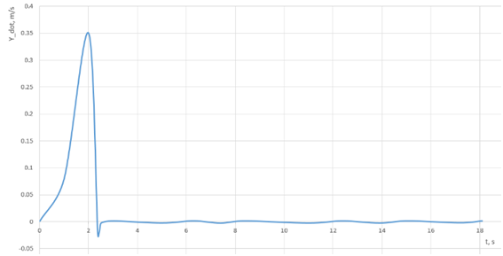
Figure 4 Spacecraft drift velocity transition processes in the normal plane in an invariant stabilization system (deterministic model).

Figure 5 Spacecraft operating device linear movement transition process in an invariant stabilization system (deterministic model).
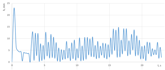
Figure 6 Spacecraft operating device linear movement transition process in a stabilization system (stochastic model).

Stability of spacecraft’s partially invariant center of the mass motion stabilization system with linear movement of the operating device

Next, we are studied the stability of a spacecraft’s partially invariant center of the mass motion stabilization system with linear movement of the operating device in more detail. After that we subsequently select the parameters for the stabilization controller that provides enough stability margins in the system and the required characteristics of the quality of the transition process. First, we considered the stability of the stabilization system without accounting for the nonlinearity of the control actuator. To do this, we write the characteristic equation, Equation (9), in canonical form:

α 0 λ 4 + α 1 λ 3 + α 2 λ 2 + α 3 MathType@MTEF@5@5@+= feaagKart1ev2aaatCvAUfeBSjuyZL2yd9gzLbvyNv2CaerbuLwBLn hiov2DGi1BTfMBaeXatLxBI9gBaerbd9wDYLwzYbItLDharqqtubsr 4rNCHbGeaGqkY=wjYJH8sqFD0xXdHaVhbbf9v8qqaqFr0xc9pk0xbb a9q8WqFfeaY=biLkVcLq=JHqpepeea0=as0Fb9pgeaYRXxe9vr0=vr 0=vqpWqaaeaabiGaciaacaqabeaadaqaaqaaaOqaaiabeg7aHnaaBa aaleaacaaIWaaabeaakiabeU7aSnaaCaaaleqabaGaaGinaaaakiab gUcaRiabeg7aHnaaBaaaleaacaaIXaaabeaakiabeU7aSnaaCaaale qabaGaaG4maaaakiabgUcaRiabeg7aHnaaBaaaleaacaaIYaaabeaa kiabeU7aSnaaCaaaleqabaGaaGOmaaaakiabgUcaRiabeg7aHnaaBa aaleaacaaIZaaabeaaaaa@4D00@

where the coefficients of the characteristic equation of a closed-loop system are as follows:

α 0 = 1 K CA ; α 1 = C ϑh k ϑ ¨ ; α 2 = C ϑh k ϑ ˙ ; α 3 = C yϑ C ϑh k y ¨ ; α 4 = C yϑ C ϑh k y ˙ . MathType@MTEF@5@5@+= feaagKart1ev2aaatCvAUfeBSjuyZL2yd9gzLbvyNv2CaerbuLwBLn hiov2DGi1BTfMBaeXatLxBI9gBaerbd9wDYLwzYbItLDharqqtubsr 4rNCHbGeaGqkY=wjYJH8sqFD0xXdHaVhbbf9v8qqaqFr0xc9pk0xbb a9q8WqFfeaY=biLkVcLq=JHqpepeea0=as0Fb9pgeaYRXxe9vr0=vr 0=vqpWqaaeaabiGaciaacaqabeaadaqaaqaaaOqaaiabeg7aHnaaBa aaleaacaaIWaaabeaakiabg2da9maalaaabaGaaGymaaqaaiaadUea daWgaaWcbaGaam4qaiaadgeaaeqaaaaakiaacUdacqaHXoqydaWgaa WcbaGaaGymaaqabaGccqGH9aqpcaWGdbWaaSbaaSqaaiabeg9akjaa dIgaaeqaaOGaam4AamaaBaaaleaacuaHrpGsgaWaaaqabaGccaGG7a GaeqySde2aaSbaaSqaaiaaikdaaeqaaOGaeyypa0Jaam4qamaaBaaa leaacqaHrpGscaWGObaabeaakiaadUgadaWgaaWcbaGafqy0dOKbai aaaeqaaOGaai4oaiabeg7aHnaaBaaaleaacaaIZaaabeaakiabg2da 9iaadoeadaWgaaWcbaGaamyEaiabeg9akbqabaGccaWGdbWaaSbaaS qaaiabeg9akjaadIgaaeqaaOGaam4AamaaBaaaleaaceWG5bGbamaa aeqaaOGaai4oaiabeg7aHnaaBaaaleaacaaI0aaabeaakiabg2da9i aadoeadaWgaaWcbaGaamyEaiabeg9akbqabaGccaWGdbWaaSbaaSqa aiabeg9akjaadIgaaeqaaOGaam4AamaaBaaaleaaceWG5bGbaiaaae qaaOGaaiOlaaaa@70C8@

According to the Hurwitz criterion, the necessary stability conditions for the system under consideration are as follows:

{ k ϑ ˙ , k ϑ ¨ , k y ˙ , k y ¨ >0 k ϑ ˙ > 1 K CA C yϑ k y ¨ C ϑh k ϑ ¨ + k y ˙ k y ¨ k ϑ ¨ . MathType@MTEF@5@5@+= feaagKart1ev2aaatCvAUfeBSjuyZL2yd9gzLbvyNv2CaerbuLwBLn hiov2DGi1BTfMBaeXatLxBI9gBaerbd9wDYLwzYbItLDharqqtubsr 4rNCHbGeaGqkY=wjYJH8sqFD0xXdHaVhbbf9v8qqaqFr0xc9pk0xbb a9q8WqFfeaY=biLkVcLq=JHqpepeea0=as0Fb9pgeaYRXxe9vr0=vr 0=vqpWqaaeaabiGaciaacaqabeaadaqaaqaaaOqaamaaceaabaqbae qabiqaaaqaaiaadUgadaWgaaWcbaGafqy0dOKbaiaaaeqaaOGaaiil aiaadUgadaWgaaWcbaGafqy0dOKbamaaaeqaaOGaaiilaiaadUgada WgaaWcbaGabmyEayaacaaabeaakiaacYcacaWGRbWaaSbaaSqaaiqa dMhagaWaaaqabaGccqGH+aGpcaaIWaaabaGaam4AamaaBaaaleaacu aHrpGsgaGaaaqabaGccqGH+aGpdaWcaaqaaiaaigdaaeaacaWGlbWa aSbaaSqaaiaadoeacaWGbbaabeaaaaGcdaWcaaqaaiaadoeadaWgaa WcbaGaamyEaiabeg9akbqabaGccaWGRbWaaSbaaSqaaiqadMhagaWa aaqabaaakeaacaWGdbWaaSbaaSqaaiabeg9akjaadIgaaeqaaOGaam 4AamaaBaaaleaacuaHrpGsgaWaaaqabaaaaOGaey4kaSYaaSaaaeaa caWGRbWaaSbaaSqaaiqadMhagaGaaaqabaaakeaacaWGRbWaaSbaaS qaaiqadMhagaWaaaqabaaaaOGaam4AamaaBaaaleaacuaHrpGsgaWa aaqabaGccaGGUaaaaaGaay5Eaaaaaa@638F@ (11)

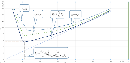
By analogy with the report,20 we constructed the stability boundaries of the stabilization system in a two-parameter plane:    the gain of the angular velocity, and k ϑ ¨ MathType@MTEF@5@5@+= feaagKart1ev2aaatCvAUfeBSjuyZL2yd9gzLbvyNv2CaerbuLwBLn hiov2DGi1BTfMBaeXatLxBI9gBaerbd9wDYLwzYbItLDharqqtubsr 4rNCHbGeaGqkY=wjYJH8sqFD0xXdHaVhbbf9v8qqaqFr0xc9pk0xbb a9q8WqFfeaY=biLkVcLq=JHqpepeea0=as0Fb9pgeaYRXxe9vr0=vr 0=vqpWqaaeaabiGaciaacaqabeaadaqaaqaaaOqaaiaadUgadaWgaa WcbaGafqy0dOKbamaaaeqaaaaa@3AF8@ - the gain in angular acceleration. The boundary of the stability region in this two-parameter plane is determined by inequality (11). If we consider the boundary to be a function of k ϑ ¨ MathType@MTEF@5@5@+= feaagKart1ev2aaatCvAUfeBSjuyZL2yd9gzLbvyNv2CaerbuLwBLn hiov2DGi1BTfMBaeXatLxBI9gBaerbd9wDYLwzYbItLDharqqtubsr 4rNCHbGeaGqkY=wjYJH8sqFD0xXdHaVhbbf9v8qqaqFr0xc9pk0xbb a9q8WqFfeaY=biLkVcLq=JHqpepeea0=as0Fb9pgeaYRXxe9vr0=vr 0=vqpWqaaeaabiGaciaacaqabeaadaqaaqaaaOqaaiaadUgadaWgaa WcbaGafqy0dOKbamaaaeqaaaaa@3AF8@ , then

F( k ϑ ¨ )= 1 K CA C yϑ C ϑh k y ¨ k ϑ ¨ + k y ˙ k y ¨ k ϑ ¨ . MathType@MTEF@5@5@+= feaagKart1ev2aaatCvAUfeBSjuyZL2yd9gzLbvyNv2CaerbuLwBLn hiov2DGi1BTfMBaeXatLxBI9gBaerbd9wDYLwzYbItLDharqqtubsr 4rNCHbGeaGqkY=wjYJH8sqFD0xXdHaVhbbf9v8qqaqFr0xc9pk0xbb a9q8WqFfeaY=biLkVcLq=JHqpepeea0=as0Fb9pgeaYRXxe9vr0=vr 0=vqpWqaaeaabiGaciaacaqabeaadaqaaqaaaOqaaiaadAeadaqada qaaiaadUgadaWgaaWcbaGafqy0dOKbamaaaeqaaaGccaGLOaGaayzk aaGaeyypa0ZaaSaaaeaacaaIXaaabaGaam4samaaBaaaleaacaWGdb GaamyqaaqabaaaaOWaaSaaaeaacaWGdbWaaSbaaSqaaiaadMhacqaH rpGsaeqaaaGcbaGaam4qamaaBaaaleaacqaHrpGscaWGObaabeaaaa GcdaWcaaqaaiaadUgadaWgaaWcbaGabmyEayaadaaabeaaaOqaaiaa dUgadaWgaaWcbaGafqy0dOKbamaaaeqaaaaakiabgUcaRmaalaaaba Gaam4AamaaBaaaleaaceWG5bGbaiaaaeqaaaGcbaGaam4AamaaBaaa leaaceWG5bGbamaaaeqaaaaakiaadUgadaWgaaWcbaGafqy0dOKbam aaaeqaaOGaaiOlaaaa@56EF@

When k ϑ ¨ MathType@MTEF@5@5@+= feaagKart1ev2aaatCvAUfeBSjuyZL2yd9gzLbvyNv2CaerbuLwBLn hiov2DGi1BTfMBaeXatLxBI9gBaerbd9wDYLwzYbItLDharqqtubsr 4rNCHbGeaGqkY=wjYJH8sqFD0xXdHaVhbbf9v8qqaqFr0xc9pk0xbb a9q8WqFfeaY=biLkVcLq=JHqpepeea0=as0Fb9pgeaYRXxe9vr0=vr 0=vqpWqaaeaabiGaciaacaqabeaadaqaaqaaaOqaaiaadUgadaWgaa WcbaGafqy0dOKbamaaaeqaaaaa@3AF8@ increases to +∞, the function F also increases to +∞, and the straight line is k ϑ ˙ = k y ˙ k y ¨ k ϑ ¨ MathType@MTEF@5@5@+= feaagKart1ev2aaatCvAUfeBSjuyZL2yd9gzLbvyNv2CaerbuLwBLn hiov2DGi1BTfMBaeXatLxBI9gBaerbd9wDYLwzYbItLDharqqtubsr 4rNCHbGeaGqkY=wjYJH8sqFD0xXdHaVhbbf9v8qqaqFr0xc9pk0xbb a9q8WqFfeaY=biLkVcLq=JHqpepeea0=as0Fb9pgeaYRXxe9vr0=vr 0=vqpWqaaeaabiGaciaacaqabeaadaqaaqaaaOqaaiaadUgadaWgaa WcbaGafqy0dOKbaiaaaeqaaOGaeyypa0ZaaSaaaeaacaWGRbWaaSba aSqaaiqadMhagaGaaaqabaaakeaacaWGRbWaaSbaaSqaaiqadMhaga WaaaqabaaaaOGaam4AamaaBaaaleaacuaHrpGsgaWaaaqabaaaaa@4340@ the asymptote. The function has a minimum at the point

F C yϑ k y ˙ K CA C ϑh min MathType@MTEF@5@5@+= feaagKart1ev2aaatCvAUfeBSjuyZL2yd9gzLbvyNv2CaerbuLwBLn hiov2DGi1BTfMBaeXatLxBI9gBaerbd9wDYLwzYbItLDharqqtubsr 4rNCHbGeaGqkY=wjYJH8sqFD0xXdHaVhbbf9v8qqaqFr0xc9pk0xbb a9q8WqFfeaY=biLkVcLq=JHqpepeea0=as0Fb9pgeaYRXxe9vr0=vr 0=vqpWqaaeaabiGaciaacaqabeaadaqaaqaaaOqaaiaadAeadaGcaa qaamaalaaabaGaam4qamaaBaaaleaacaWG5bGaeqy0dOeabeaakiaa dUgadaWgaaWcbaGabmyEayaacaaabeaaaOqaaiaadUeadaWgaaWcba Gaam4qaiaadgeaaeqaaOGaam4qamaaBaaaleaacqaHrpGscaWGObaa beaakmaaBaaaleaadaWgaaadbaGaciyBaiaacMgacaGGUbaabeaaaS qabaaaaaqabaaaaa@4843@

Thus, the stability region is presented in Figure 7 for a nearly invariant stabilization system with a linearly moving operating device.

We can determine a stable region in the parameter plane k y ˙ MathType@MTEF@5@5@+= feaagKart1ev2aaatCvAUfeBSjuyZL2yd9gzLbvyNv2CaerbuLwBLn hiov2DGi1BTfMBaeXatLxBI9gBaerbd9wDYLwzYbItLDharqqtubsr 4rNCHbGeaGqkY=wjYJH8sqFD0xXdHaVhbbf9v8qqaqFr0xc9pk0xbb a9q8WqFfeaY=biLkVcLq=JHqpepeea0=as0Fb9pgeaYRXxe9vr0=vr 0=vqpWqaaeaabiGaciaacaqabeaadaqaaqaaaOqaaiaadUgadaWgaa WcbaGabmyEayaacaaabeaaaaa@3A4D@ , k y ¨ MathType@MTEF@5@5@+= feaagKart1ev2aaatCvAUfeBSjuyZL2yd9gzLbvyNv2CaerbuLwBLn hiov2DGi1BTfMBaeXatLxBI9gBaerbd9wDYLwzYbItLDharqqtubsr 4rNCHbGeaGqkY=wjYJH8sqFD0xXdHaVhbbf9v8qqaqFr0xc9pk0xbb a9q8WqFfeaY=biLkVcLq=JHqpepeea0=as0Fb9pgeaYRXxe9vr0=vr 0=vqpWqaaeaabiGaciaacaqabeaadaqaaqaaaOqaaiaadUgadaWgaa WcbaGabmyEayaadaaabeaaaaa@3A4E@ using the function

F( k y ¨ )= k ϑ ¨ k ϑ ¨ k y ¨ C yϑ k y ¨ 2 K CA C ϑh k ϑ ¨ 2 MathType@MTEF@5@5@+= feaagKart1ev2aaatCvAUfeBSjuyZL2yd9gzLbvyNv2CaerbuLwBLn hiov2DGi1BTfMBaeXatLxBI9gBaerbd9wDYLwzYbItLDharqqtubsr 4rNCHbGeaGqkY=MjYJH8sqFD0xXdHaVhbbf9v8qqaqFr0xc9pk0xbb a9q8WqFfeaY=biLkVcLq=JHqpepeea0=as0Fb9pgeaYRXxe9vr0=vr 0=vqpWqaaeaabiGaciaacaqabeaadaqaaqaaaOqaaiaadAeadaqada qaaiaadUgadaWgaaWcbaGabmyEayaadaaabeaaaOGaayjkaiaawMca aiabg2da9maalaaabaGaam4AamaaBaaaleaacuaHrpGsgaWaaaqaba aakeaacaWGRbWaaSbaaSqaaiqbeg9akzaadaaabeaaaaGccaWGRbWa aSbaaSqaaiqadMhagaWaaaqabaGccqGHsisldaWcaaqaaiaadoeada WgaaWcbaGaamyEaiabeg9akbqabaGccaWGRbWaa0baaSqaaiqadMha gaWaaaqaaiaaikdaaaaakeaacaWGlbWaaSbaaSqaaiaadoeacaWGbb aabeaakiaadoeadaWgaaWcbaGaeqy0dOKaamiAaaqabaGccaWGRbWa a0baaSqaaiqbeg9akzaadaaabaGaaGOmaaaaaaaaaa@56DF@

This function decreases to 0 at points k y ¨ =0, k y ¨ = K CA C ϑh C yϑ k ϑ ˙ k ϑ ¨ . MathType@MTEF@5@5@+= feaagKart1ev2aaatCvAUfeBSjuyZL2yd9gzLbvyNv2CaerbuLwBLn hiov2DGi1BTfMBaeXatLxBI9gBaerbd9wDYLwzYbItLDharqqtubsr 4rNCHbGeaGqkY=wjYJH8sqFD0xXdHaVhbbf9v8qqaqFr0xc9pk0xbb a9q8WqFfeaY=biLkVcLq=JHqpepeea0=as0Fb9pgeaYRXxe9vr0=vr 0=vqpWqaaeaabiGaciaacaqabeaadaqaaqaaaOqaaiaadUgadaWgaa WcbaGabmyEayaadaaabeaakiabg2da9iaaicdacaGGSaGaam4Aamaa BaaaleaaceWG5bGbamaaaeqaaOGaeyypa0Jaam4samaaBaaaleaaca WGdbGaamyqaaqabaGcdaWcaaqaaiaadoeadaWgaaWcbaGaeqy0dOKa amiAaaqabaaakeaacaWGdbWaaSbaaSqaaiaadMhacqaHrpGsaeqaaa aakiaadUgadaWgaaWcbaGafqy0dOKbaiaaaeqaaOGaam4AamaaBaaa leaacuaHrpGsgaWaaaqabaGccaGGUaaaaa@5038@

 The function reaches the maximum value F 1 2 K CA C ϑh 2 C yϑ ϑ ˙ max MathType@MTEF@5@5@+= feaagKart1ev2aaatCvAUfeBSjuyZL2yd9gzLbvyNv2CaerbuLwBLn hiov2DGi1BTfMBaeXatLxBI9gBaerbd9wDYLwzYbItLDharqqtubsr 4rNCHbGeaGqkY=wjYJH8sqFD0xXdHaVhbbf9v8qqaqFr0xc9pk0xbb a9q8WqFfeaY=biLkVcLq=JHqpepeea0=as0Fb9pgeaYRXxe9vr0=vr 0=vqpWqaaeaabiGaciaacaqabeaadaqaaqaaaOqaaiaacAeadaWcaa qaaiaaigdaaeaacaaIYaaaamaalaaabaGaam4samaaBaaaleaacaWG dbGaamyqaaqabaGccaWGdbWaaSbaaSqaaiabeg9akjaadIgaaeqaaO WaaWbaaSqabeaacaaIYaaaaaGcbaGaam4qamaaBaaaleaacaWG5bGa eqy0dOeabeaakiqbeg9akzaacaWaaSbaaSqaaiGac2gacaGGHbGaai iEaaqabaaaaaaa@49FA@ at the point k y ¨ = K CA C ϑh 2 C yϑ k ϑ ˙ k ϑ ¨ . MathType@MTEF@5@5@+= feaagKart1ev2aaatCvAUfeBSjuyZL2yd9gzLbvyNv2CaerbuLwBLn hiov2DGi1BTfMBaeXatLxBI9gBaerbd9wDYLwzYbItLDharqqtubsr 4rNCHbGeaGqkY=wjYJH8sqFD0xXdHaVhbbf9v8qqaqFr0xc9pk0xbb a9q8WqFfeaY=biLkVcLq=JHqpepeea0=as0Fb9pgeaYRXxe9vr0=vr 0=vqpWqaaeaabiGaciaacaqabeaadaqaaqaaaOqaaiaadUgadaWgaa WcbaGabmyEayaadaaabeaakiabg2da9iaadUeadaWgaaWcbaGaam4q aiaadgeaaeqaaOWaaSaaaeaacaWGdbWaaSbaaSqaaiabeg9akjaadI gaaeqaaaGcbaGaaGOmaiaadoeadaWgaaWcbaGaamyEaiabeg9akbqa baaaaOGaam4AamaaBaaaleaacuaHrpGsgaGaaaqabaGccaWGRbWaaS baaSqaaiqbeg9akzaadaaabeaakiaac6caaaa@4C56@

The stability region of the system in the parameter plane is presented in Figure 8 ( i max I H ) MathType@MTEF@5@5@+= feaagKart1ev2aaatCvAUfeBSjuyZL2yd9gzLbvyNv2CaerbuLwBLn hiov2DGi1BTfMBaeXatLxBI9gBaerbd9wDYLwzYbItLDharqqtubsr 4rNCHbGeaGqkY=wjYJH8sqFD0xXdHaVhbbf9v8qqaqFr0xc9pk0xbb a9q8WqFfeaY=biLkVcLq=JHqpepeea0=as0Fb9pgeaYRXxe9vr0=vr 0=vqpWqaaeaabiGaciaacaqabeaadaqaaqaaaOqaamaabmaabaGaam yAamaaBaaaleaaciGGTbGaaiyyaiaacIhaaeqaaOGaeyizImQaamys amaaBaaaleaacaWGibaabeaaaOGaayjkaiaawMcaaaaa@4131@

According to the equation (6), the response function of the linear part of the system shall be as follows:

W L ( jω )= K CA ω 4 [ j ω 3 C ϑh k ϑ ¨ + ω 2 C ϑh k ϑ ˙ jω C ϑh C yϑ k y ¨ C ϑh C yϑ k y ˙ ]. MathType@MTEF@5@5@+= feaagKart1ev2aaatCvAUfeBSjuyZL2yd9gzLbvyNv2CaerbuLwBLn hiov2DGi1BTfMBaeXatLxBI9gBaerbd9wDYLwzYbItLDharqqtubsr 4rNCHbGeaGqkY=wjYJH8sqFD0xXdHaVhbbf9v8qqaqFr0xc9pk0xbb a9q8WqFfeaY=biLkVcLq=JHqpepeea0=as0Fb9pgeaYRXxe9vr0=vr 0=vqpWqaaeaabiGaciaacaqabeaadaqaaqaaaOqaaiaadEfadaWgaa WcbaGaamitaaqabaGcdaqadaqaaiaadQgacqaHjpWDaiaawIcacaGL PaaacqGH9aqpdaWcaaqaaiaadUeadaWgaaWcbaGaam4qaiaadgeaae qaaaGcbaGaeqyYdC3aaWbaaSqabeaacaaI0aaaaaaakmaadmaabaGa amOAaiabeM8a3naaCaaaleqabaGaaG4maaaakiaadoeadaWgaaWcba Gaeqy0dOKaamiAaaqabaGccaWGRbWaaSbaaSqaaiqbeg9akzaadaaa beaakiabgUcaRiabeM8a3naaCaaaleqabaGaaGOmaaaakiaadoeada WgaaWcbaGaeqy0dOKaamiAaaqabaGccaWGRbWaaSbaaSqaaiqbeg9a kzaacaaabeaakiabgkHiTiaadQgacqaHjpWDcaWGdbWaaSbaaSqaai abeg9akjaadIgaaeqaaOGaam4qamaaBaaaleaacaWG5bGaeqy0dOea beaakiaadUgadaWgaaWcbaGabmyEayaadaaabeaakiabgkHiTiabgk HiTiaadoeadaWgaaWcbaGaeqy0dOKaamiAaaqabaGccaWGdbWaaSba aSqaaiaadMhacqaHrpGsaeqaaOGaam4AamaaBaaaleaaceWG5bGbai aaaeqaaaGccaGLBbGaayzxaaGaaiOlaaaa@73D5@ (12)

We introduce the following notations:
β 1 = C ϑh k ϑ ¨ ; β 2 = C ϑh k ϑ ˙ ; β 3 = C yϑ C ϑh k y ¨ ; β 4 == C yϑ C ϑh k y ˙ . MathType@MTEF@5@5@+= feaagKart1ev2aaatCvAUfeBSjuyZL2yd9gzLbvyNv2CaerbuLwBLn hiov2DGi1BTfMBaeXatLxBI9gBaerbd9wDYLwzYbItLDharqqtubsr 4rNCHbGeaGqkY=wjYJH8sqFD0xXdHaVhbbf9v8qqaqFr0xc9pk0xbb a9q8WqFfeaY=biLkVcLq=JHqpepeea0=as0Fb9pgeaYRXxe9vr0=vr 0=vqpWqaaeaabiGaciaacaqabeaadaqaaqaaaOqaaiabek7aInaaBa aaleaacaaIXaaabeaakiabg2da9iaadoeadaWgaaWcbaGaeqy0dOKa amiAaaqabaGccaWGRbWaaSbaaSqaaiqbeg9akzaadaaabeaakiaacU dacqaHYoGydaWgaaWcbaGaaGOmaaqabaGccqGH9aqpcaWGdbWaaSba aSqaaiabeg9akjaadIgaaeqaaOGaam4AamaaBaaaleaacuaHrpGsga GaaaqabaGccaGG7aGaeqOSdi2aaSbaaSqaaiaaiodaaeqaaOGaeyyp a0Jaam4qamaaBaaaleaacaWG5bGaeqy0dOeabeaakiaadoeadaWgaa WcbaGaeqy0dOKaamiAaaqabaGccaWGRbWaaSbaaSqaaiqadMhagaWa aaqabaGccaGG7aGaeqOSdi2aaSbaaSqaaiaaisdaaeqaaOGaeyypa0 Jaeyypa0Jaam4qamaaBaaaleaacaWG5bGaeqy0dOeabeaakiaadoea daWgaaWcbaGaeqy0dOKaamiAaaqabaGccaWGRbWaaSbaaSqaaiqadM hagaGaaaqabaGccaGGUaaaaa@6A23@

Figure 7 General view of the stability region within the stabilization system with linear movement of the operating device in the k_y ̇ ,k_y ̈  parameter plane. 
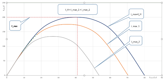
Figure 8 Completed structure design.

Based on Equation (12) and using the notation defined above, the expressions for the real and imaginary parts of the response function of the linear part of the system are as follows:

Re( W L )= K CA ω 4 ( ω 2 β 2 β 4 ), MathType@MTEF@5@5@+= feaagKart1ev2aaatCvAUfeBSjuyZL2yd9gzLbvyNv2CaerbuLwBLn hiov2DGi1BTfMBaeXatLxBI9gBaerbd9wDYLwzYbItLDharqqtubsr 4rNCHbGeaGqkY=wjYJH8sqFD0xXdHaVhbbf9v8qqaqFr0xc9pk0xbb a9q8WqFfeaY=biLkVcLq=JHqpepeea0=as0Fb9pgeaYRXxe9vr0=vr 0=vqpWqaaeaabiGaciaacaqabeaadaqaaqaaaOqaaiaackfacaGGLb WaaeWaaeaacaWGxbWaaSbaaSqaaiaadYeaaeqaaaGccaGLOaGaayzk aaGaeyypa0ZaaSaaaeaacaWGlbWaaSbaaSqaaiaadoeacaWGbbaabe aaaOqaaiabeM8a3naaCaaaleqabaGaaGinaaaaaaGcdaqadaqaaiab eM8a3naaCaaaleqabaGaaGOmaaaakiabek7aInaaBaaaleaacaaIYa aabeaakiabgkHiTiabek7aInaaBaaaleaacaaI0aaabeaaaOGaayjk aiaawMcaaiaacYcaaaa@4ECF@ (13)

Im( W L )=j K CA ω 4 ( ω 3 β 1 ω β 3 ). MathType@MTEF@5@5@+= feaagKart1ev2aaatCvAUfeBSjuyZL2yd9gzLbvyNv2CaerbuLwBLn hiov2DGi1BTfMBaeXatLxBI9gBaerbd9wDYLwzYbItLDharqqtubsr 4rNCHbGeaGqkY=wjYJH8sqFD0xXdHaVhbbf9v8qqaqFr0xc9pk0xbb a9q8WqFfeaY=biLkVcLq=JHqpepeea0=as0Fb9pgeaYRXxe9vr0=vr 0=vqpWqaaeaabiGaciaacaqabeaadaqaaqaaaOqaaiaacMeacaGGTb WaaeWaaeaacaWGxbWaaSbaaSqaaiaadYeaaeqaaaGccaGLOaGaayzk aaGaeyypa0JaamOAamaalaaabaGaam4samaaBaaaleaacaWGdbGaam yqaaqabaaakeaacqaHjpWDdaahaaWcbeqaaiaaisdaaaaaaOWaaeWa aeaacqaHjpWDdaahaaWcbeqaaiaaiodaaaGccqaHYoGydaWgaaWcba GaaGymaaqabaGccqGHsislcqaHjpWDcqaHYoGydaWgaaWcbaGaaG4m aaqabaaakiaawIcacaGLPaaacaGGUaaaaa@518B@ (14)

Equations (13) and (14) coincide up to the coefficients β with the expressions for the stabilization system with the rotation of the OD.32,35 Also, the same are nonlinear characteristic and the expression for the harmonic linearization coefficient. Thus, for a system with linear movement of the PS, the following were determined.

  1. There is an unstable limit cycle in the system. The frequency of this limit cycle is

W Lim ( jω )= β 3 β 1 = C yϑ k y ¨ k ϑ ¨ , MathType@MTEF@5@5@+= feaagKart1ev2aaatCvAUfeBSjuyZL2yd9gzLbvyNv2CaerbuLwBLn hiov2DGi1BTfMBaeXatLxBI9gBaerbd9wDYLwzYbItLDharqqtubsr 4rNCHbGeaGqkY=wjYJH8sqFD0xXdHaVhbbf9v8qqaqFr0xc9pk0xbb a9q8WqFfeaY=biLkVcLq=JHqpepeea0=as0Fb9pgeaYRXxe9vr0=vr 0=vqpWqaaeaabiGaciaacaqabeaadaqaaqaaaOqaaiaacEfadaWgaa WcbaGaaiitaiaacMgacaGGTbaabeaakmaabmaabaGaamOAaiabeM8a 3bGaayjkaiaawMcaaiabg2da9maakaaabaWaaSaaaeaacqaHYoGyda WgaaWcbaGaaG4maaqabaaakeaacqaHYoGydaWgaaWcbaGaaGymaaqa baaaaaqabaGccqGH9aqpdaGcaaqaamaalaaabaGaam4qamaaBaaale aacaWG5bGaeqy0dOeabeaakiaadUgadaWgaaWcbaGabmyEayaadaaa beaaaOqaaiaadUgadaWgaaWcbaGafqy0dOKbamaaaeqaaaaaaeqaaO Gaaiilaaaa@50FA@

2 π ( arcsin I H i max I H i max 1 I H 2 i max 2 ω 4 K CA ( ω Lim 2 C ϑh k ϑ ˙ C ϑh C yϑ k y ˙ ) ) MathType@MTEF@5@5@+= feaagKart1ev2aaatCvAUfeBSjuyZL2yd9gzLbvyNv2CaerbuLwBLn hiov2DGi1BTfMBaeXatLxBI9gBaerbd9wDYLwzYbItLDharqqtubsr 4rNCHbGeaGqkY=wjYJH8sqFD0xXdHaVhbbf9v8qqaqFr0xc9pk0xbb a9q8WqFfeaY=biLkVcLq=JHqpepeea0=as0Fb9pgeaYRXxe9vr0=vr 0=vqpWqaaeaabiGaciaacaqabeaadaqaaqaaaOqaamaalaaabaGaaG Omaaqaaiabec8aWbaadaqadaqaaiGacggacaGGYbGaai4yaiaacoha caGGPbGaaiOBamaalaaabaGaamysamaaBaaaleaacaWGibaabeaaaO qaaiaadMgadaWgaaWcbaGaciyBaiaacggacaGG4baabeaakmaalaaa baGaamysamaaBaaaleaacaWGibaabeaaaOqaaiaadMgadaWgaaWcba GaciyBaiaacggacaGG4baabeaakmaakaaabaGaaGymaiabgkHiTmaa laaabaGaamysamaaDaaaleaacaWGibaabaGaaGOmaaaaaOqaaiaadM gadaqhaaWcbaGaciyBaiaacggacaGG4baabaGaaGOmaaaaaaaabeaa aaGcdaWcaaqaaiabeM8a3naaCaaaleqabaGaaGinaaaaaOqaaiaadU eadaWgaaWcbaGaam4qaiaadgeaaeqaaOWaaeWaaeaacqaHjpWDdaqh aaWcbaGaamitaiaadMgacaWGTbaabaGaaGOmaaaakiaadoeadaWgaa WcbaGaeqy0dOKaamiAaaqabaGccaWGRbWaaSbaaSqaaiqbeg9akzaa caaabeaakiabgkHiTiaadoeadaWgaaWcbaGaeqy0dOKaamiAaaqaba GccaWGdbWaaSbaaSqaaiaadMhacqaHrpGsaeqaaOGaam4AamaaBaaa leaaceWG5bGbaiaaaeqaaaGccaGLOaGaayzkaaaaaaaaaiaawIcaca GLPaaaaaa@73AE@

where I H MathType@MTEF@5@5@+= feaagKart1ev2aaatCvAUfeBSjuyZL2yd9gzLbvyNv2CaerbuLwBLn hiov2DGi1BTfMBaeXatLxBI9gBaerbd9wDYLwzYbItLDharqqtubsr 4rNCHbGeaGqkY=wjYJH8sqFD0xXdHaVhbbf9v8qqaqFr0xc9pk0xbb a9q8WqFfeaY=biLkVcLq=JHqpepeea0=as0Fb9pgeaYRXxe9vr0=vr 0=vqpWqaaeaabiGaciaacaqabeaadaqaaqaaaOqaaiaadMeadaWgaa WcbaGaamisaaqabaaaaa@39F1@ - is the value of the saturation current in the control actuator, and i max MathType@MTEF@5@5@+= feaagKart1ev2aaatCvAUfeBSjuyZL2yd9gzLbvyNv2CaerbuLwBLn hiov2DGi1BTfMBaeXatLxBI9gBaerbd9wDYLwzYbItLDharqqtubsr 4rNCHbGeaGqkY=wjYJH8sqFD0xXdHaVhbbf9v8qqaqFr0xc9pk0xbb a9q8WqFfeaY=biLkVcLq=JHqpepeea0=as0Fb9pgeaYRXxe9vr0=vr 0=vqpWqaaeaabiGaciaacaqabeaadaqaaqaaaOqaaiaadMgadaWgaa WcbaGaciyBaiaacggacaGG4baabeaaaaa@3C18@ -  is the amplitude of the nonlinear element input signal. The stability condition for the system is determined by the initial conditions of the transition process, at which the amplitude at the input of the nonlinear element is less than the value i max MathType@MTEF@5@5@+= feaagKart1ev2aaatCvAUfeBSjuyZL2yd9gzLbvyNv2CaerbuLwBLn hiov2DGi1BTfMBaeXatLxBI9gBaerbd9wDYLwzYbItLDharqqtubsr 4rNCHbGeaGqkY=wjYJH8sqFD0xXdHaVhbbf9v8qqaqFr0xc9pk0xbb a9q8WqFfeaY=biLkVcLq=JHqpepeea0=as0Fb9pgeaYRXxe9vr0=vr 0=vqpWqaaeaabiGaciaacaqabeaadaqaaqaaaOqaaiaadMgadaWgaa WcbaGaciyBaiaacggacaGG4baabeaaaaa@3C18@ .

  1. The stability conditions of this system determined by the stabilization controller coefficients are as follows:

form:

k ϑ ˙ > 1 K CA q( i max C yϑ k y ¨ k y ˙ C ϑh k ϑ ¨ k y ¨ ϑ ¨ , MathType@MTEF@5@5@+= feaagKart1ev2aaatCvAUfeBSjuyZL2yd9gzLbvyNv2CaerbuLwBLn hiov2DGi1BTfMBaeXatLxBI9gBaerbd9wDYLwzYbItLDharqqtubsr 4rNCHbGeaGqkY=wjYJH8sqFD0xXdHaVhbbf9v8qqaqFr0xc9pk0xbb a9q8WqFfeaY=biLkVcLq=JHqpepeea0=as0Fb9pgeaYRXxe9vr0=vr 0=vqpWqaaeaabiGaciaacaqabeaadaqaaqaaaOqaaiaadUgadaWgaa WcbaGafqy0dOKbaiaaaeqaaOGaeyOpa4ZaaSaaaeaacaaIXaaabaGa am4samaaBaaaleaacaWGdbGaamyqaaqabaGccaWGXbWaaeqaaeaaca WGPbWaaSbaaSqaaiGac2gacaGGHbGaaiiEaaqabaGcdaWcaaqaaiaa doeadaWgaaWcbaGaamyEaiabeg9akbqabaGccaWGRbWaaSbaaSqaai qadMhagaWaaaqabaGccaWGRbWaaSbaaSqaaiqadMhagaGaaaqabaaa keaacaWGdbWaaSbaaSqaaiabeg9akjaadIgaaeqaaOGaam4AamaaBa aaleaacuaHrpGsgaWaaaqabaGccaWGRbWaaSbaaSqaaiqadMhagaWa aaqabaGcdaWgaaWcbaWaaSbaaWqaaiqbeg9akzaadaaabeaaaSqaba aaaaGccaGLOaaaaaGaaiilaaaa@5894@

or

k y ˙ < k ϑ ˙ k ϑ ¨ k y ¨ 1 K CA q( i max C yϑ k y ¨ 2 C ϑh k ϑ ¨ k ϑ ¨ 2 MathType@MTEF@5@5@+= feaagKart1ev2aaatCvAUfeBSjuyZL2yd9gzLbvyNv2CaerbuLwBLn hiov2DGi1BTfMBaeXatLxBI9gBaerbd9wDYLwzYbItLDharqqtubsr 4rNCHbGeaGqkY=wjYJH8sqFD0xXdHaVhbbf9v8qqaqFr0xc9pk0xbb a9q8WqFfeaY=biLkVcLq=JHqpepeea0=as0Fb9pgeaYRXxe9vr0=vr 0=vqpWqaaeaabiGaciaacaqabeaadaqaaqaaaOqaaiaadUgadaWgaa WcbaGabmyEayaacaaabeaakiabgYda8maalaaabaGaam4AamaaBaaa leaacuaHrpGsgaGaaaqabaaakeaacaWGRbWaaSbaaSqaaiqbeg9akz aadaaabeaaaaGccaWGRbWaaSbaaSqaaiqadMhagaWaaaqabaGccqGH sisldaWcaaqaaiaaigdaaeaacaWGlbWaaSbaaSqaaiaadoeacaWGbb aabeaakiaadghadaqabaqaaiaadMgadaWgaaWcbaGaciyBaiaacgga caGG4baabeaakmaalaaabaGaam4qamaaBaaaleaacaWG5bGaeqy0dO eabeaakiaadUgadaqhaaWcbaGabmyEayaadaaabaGaaGOmaaaaaOqa aiaadoeadaWgaaWcbaGaeqy0dOKaamiAaaqabaGccaWGRbWaaSbaaS qaaiqbeg9akzaadaaabeaakiaadUgadaqhaaWcbaGafqy0dOKbamaa aeaacaaIYaaaaaaaaOGaayjkaaaaaaaa@5DE7@

Accordingly, the stability regions in the k ϑ ˙ MathType@MTEF@5@5@+= feaagKart1ev2aaatCvAUfeBSjuyZL2yd9gzLbvyNv2CaerbuLwBLn hiov2DGi1BTfMBaeXatLxBI9gBaerbd9wDYLwzYbItLDharqqtubsr 4rNCHbGeaGqkY=wjYJH8sqFD0xXdHaVhbbf9v8qqaqFr0xc9pk0xbb a9q8WqFfeaY=biLkVcLq=JHqpepeea0=as0Fb9pgeaYRXxe9vr0=vr 0=vqpWqaaeaabiGaciaacaqabeaadaqaaqaaaOqaaiaadUgadaWgaa WcbaGafqy0dOKbaiaaaeqaaaaa@3AF7@ , k ϑ ¨ MathType@MTEF@5@5@+= feaagKart1ev2aaatCvAUfeBSjuyZL2yd9gzLbvyNv2CaerbuLwBLn hiov2DGi1BTfMBaeXatLxBI9gBaerbd9wDYLwzYbItLDharqqtubsr 4rNCHbGeaGqkY=wjYJH8sqFD0xXdHaVhbbf9v8qqaqFr0xc9pk0xbb a9q8WqFfeaY=biLkVcLq=JHqpepeea0=as0Fb9pgeaYRXxe9vr0=vr 0=vqpWqaaeaabiGaciaacaqabeaadaqaaqaaaOqaaiaadUgadaWgaa WcbaGafqy0dOKbamaaaeqaaaaa@3AF8@ and k y ˙ MathType@MTEF@5@5@+= feaagKart1ev2aaatCvAUfeBSjuyZL2yd9gzLbvyNv2CaerbuLwBLn hiov2DGi1BTfMBaeXatLxBI9gBaerbd9wDYLwzYbItLDharqqtubsr 4rNCHbGeaGqkY=wjYJH8sqFD0xXdHaVhbbf9v8qqaqFr0xc9pk0xbb a9q8WqFfeaY=biLkVcLq=JHqpepeea0=as0Fb9pgeaYRXxe9vr0=vr 0=vqpWqaaeaabiGaciaacaqabeaadaqaaqaaaOqaaiaadUgadaWgaa WcbaGabmyEayaacaaabeaaaaa@3A4D@ , k y ¨ MathType@MTEF@5@5@+= feaagKart1ev2aaatCvAUfeBSjuyZL2yd9gzLbvyNv2CaerbuLwBLn hiov2DGi1BTfMBaeXatLxBI9gBaerbd9wDYLwzYbItLDharqqtubsr 4rNCHbGeaGqkY=wjYJH8sqFD0xXdHaVhbbf9v8qqaqFr0xc9pk0xbb a9q8WqFfeaY=biLkVcLq=JHqpepeea0=as0Fb9pgeaYRXxe9vr0=vr 0=vqpWqaaeaabiGaciaacaqabeaadaqaaqaaaOqaaiaadUgadaWgaa WcbaGabmyEayaadaaabeaaaaa@3A4E@ parameter planes for different values of the inputs of the nonlinear elements have similar forms to the corresponding stability regions for the systems reported previously.34,35

  1. The system is missing an absolute stability area. The stability of the system will be determined by the choice of parameters for the stabilization controller and the initial conditions of the transition process, i.e., by the disturbances.

We next examine the parameter selection for the stabilization controller to minimize the maximum dynamic error of the drift velocity under the requirements of enough stability margins.19 The general view of the stability region for the stabilization system with linear movement of the PS coincides with the general view of the stability region for the stabilization system with a rotating PS. Thus, we can apply the algorithm described previously1,4 to select stabilization controller parameters. An application of the specified algorithm with stable solutions for the partially invariant center of mass motion stabilization system for China’s HX-1 Mars Mission Spacecraft31 was examined.

The stability analysis approximately at the selected operating point k ϑ ˙ =4.1; k ϑ ¨ =0.7s MathType@MTEF@5@5@+= feaagKart1ev2aaatCvAUfeBSjuyZL2yd9gzLbvyNv2CaerbuLwBLn hiov2DGi1BTfMBaeXatLxBI9gBaerbd9wDYLwzYbItLDharqqtubsr 4rNCHbGeaGqkY=wjYJH8sqFD0xXdHaVhbbf9v8qqaqFr0xc9pk0xbb a9q8WqFfeaY=biLkVcLq=JHqpepeea0=as0Fb9pgeaYRXxe9vr0=vr 0=vqpWqaaeaabiGaciaacaqabeaadaqaaqaaaOqaaiaadUgadaWgaa WcbaGafqy0dOKbaiaaaeqaaOGaeyypa0JaaGinaiaac6cacaaIXaGa ai4oaiaadUgadaWgaaWcbaGafqy0dOKbamaaaeqaaOGaeyypa0JaaG imaiaac6cacaaI3aGaam4Caaaa@45F4@ for the angular stabilization channel (Step 9 of the parameter selection algorithm)34 also confirmed the presence of enough stability margins. The position of the selected parameters for the stabilization controller with respect to the stability boundary of the system is shown in Figures 9 & 10.
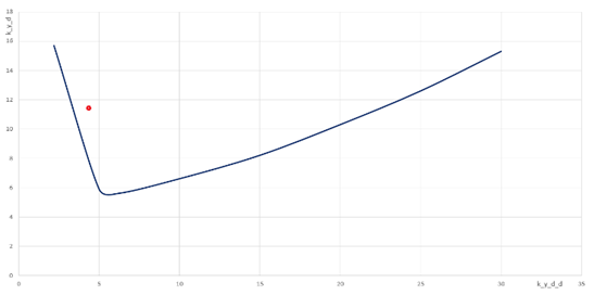
Figure 9 Position of the selected parameters for angular stabilization channel with respect to the stability boundary of the system.
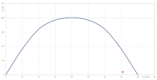
Figure 10 Position of the selected parameters for the center of mass movement stabilization channel with respect to the stability boundary of the system.

Estimation of fuel economy during corrections and reduction of spacecraft mission due to the use of invariant algorithms for stabilization

We evaluated the efficiency of the invariant stabilization algorithms for China’s HX-1 Mars Mission Spacecraft.31 We used the mass of fuel, which can be conserved by increasing the accuracy of stabilization tangential velocities in the correction phases, as an efficiency criterion. For subsequent modifications of this type of spacecraft, we proposed the following scheme for corrective maneuvers in the interplanetary portion of the flight. The first correction of the trajectory was carried out 7-9 days after the launch, and it was designed to correct positioning errors. The second correction, to correct the errors of the first correction, was made 30 d before approaching Mars. Finally, the third correction was made 4-5 days before rendezvousing with the planet to ensure the required navigation accuracy of the spacecraft.

For the corrective maneuvers, it was assumed that the PS used a thrust of 2000 kg and a specific impulse of 317 s. In this case, the longitudinal and lateral errors of the corrective maneuver should be 0.2m/s  and 0.4m/s, respectively. In the preliminary design estimates of the fuel reserves for the correction of the spacecraft trajectory, a “guaranteed” approach was used. It is believed that execution errors could reach maximum values during each correction. For the HX-1 spacecraft, the speed during the first correction should not exceed 20m/s during the second and third 10m/s.  It is accepted that the error of the maneuver does not depend on the speed of correction in the range of 1...30 m/s. In this case, the reduction in the maximum (lateral) error of execution led to a proportional reduction of the speed during the second and third corrections.

The mass of the fuel, M F MathType@MTEF@5@5@+= feaagKart1ev2aaatCvAUfeBSjuyZL2yd9gzLbvyNv2CaerbuLwBLn hiov2DGi1BTfMBaeXatLxBI9gBaerbd9wDYLwzYbItLDharqqtubsr 4rNCHbGeaGqkY=wjYJH8sqFD0xXdHaVhbbf9v8qqaqFr0xc9pk0xbb a9q8WqFfeaY=biLkVcLq=JHqpepeea0=as0Fb9pgeaYRXxe9vr0=vr 0=vqpWqaaeaabiGaciaacaqabeaadaqaaqaaaOqaaiaad2eadaWgaa WcbaGaamOraaqabaaaaa@39F3@ , required for two corrections with the total velocity pulse V 23 MathType@MTEF@5@5@+= feaagKart1ev2aaatCvAUfeBSjuyZL2yd9gzLbvyNv2CaerbuLwBLn hiov2DGi1BTfMBaeXatLxBI9gBaerbd9wDYLwzYbItLDharqqtubsr 4rNCHbGeaGqkY=wjYJH8sqFD0xXdHaVhbbf9v8qqaqFr0xc9pk0xbb a9q8WqFfeaY=biLkVcLq=JHqpepeea0=as0Fb9pgeaYRXxe9vr0=vr 0=vqpWqaaeaabiGaciaacaqabeaadaqaaqaaaOqaaiaadAfadaWgaa WcbaGaaGOmaiaaiodaaeqaaaaa@3AAA@ ,  was determined as follows:

M F = M Sc g P specific V 23 , MathType@MTEF@5@5@+= feaagKart1ev2aaatCvAUfeBSjuyZL2yd9gzLbvyNv2CaerbuLwBLn hiov2DGi1BTfMBaeXatLxBI9gBaerbd9wDYLwzYbItLDharqqtubsr 4rNCHbGeaGqkY=wjYJH8sqFD0xXdHaVhbbf9v8qqaqFr0xc9pk0xbb a9q8WqFfeaY=biLkVcLq=JHqpepeea0=as0Fb9pgeaYRXxe9vr0=vr 0=vqpWqaaeaabiGaciaacaqabeaadaqaaqaaaOqaaiaad2eadaWgaa WcbaGaamOraaqabaGccqGH9aqpdaWcaaqaaiaad2eadaWgaaWcbaGa am4uaiaadogaaeqaaaGcbaGaam4zaiaadcfadaWgaaWcbaGaam4Cai aadchacaWGLbGaam4yaiaadMgacaWGMbGaamyAaiaadogaaeqaaaaa kiaadAfadaWgaaWcbaGaaGOmaiaaiodaaeqaaOGaaiilaaaa@4A7A@

For the HX-1 spacecraft, with a mass of about 5000 kg, a correction of 1.0 m/s requires 1.6 kg of fuel. Therefore, by a double reduction of the correction error, for example, (from 0.4 m/s to 0.2 m/s)) we reduced the total speed of the second and third corrections to 10 m/s  and saved approximately 16 kg in spacecraft mass. Accordingly, a 10-time reduction in the lateral error during the corrective maneuver using the new system of the center of mass stabilization will reduce the total speed V 23 MathType@MTEF@5@5@+= feaagKart1ev2aaatCvAUfeBSjuyZL2yd9gzLbvyNv2CaerbuLwBLn hiov2DGi1BTfMBaeXatLxBI9gBaerbd9wDYLwzYbItLDharqqtubsr 4rNCHbGeaGqkY=wjYJH8sqFD0xXdHaVhbbf9v8qqaqFr0xc9pk0xbb a9q8WqFfeaY=biLkVcLq=JHqpepeea0=as0Fb9pgeaYRXxe9vr0=vr 0=vqpWqaaeaabiGaciaacaqabeaadaqaaqaaaOqaaiaadAfadaWgaa WcbaGaaGOmaiaaiodaaeqaaaaa@3AAA@ to and thereby save up to 28 kg of fuel. For the HX-1 spacecraft, 28 kg is approximately 4% of the mass of the payload.

To estimate the spacecraft mission the perspective plane, we used approximate calculation methods in the initial stages of design.17 These methods consider a linear mathematical model (the deviation of the real trajectory from the software designed trajectory is a linear function of the disturbing factors). For example, the gravitational sphere entrance coordinate error for the destination planet is a linear function of the correction speed pulse error and the error of the initial position of the spacecraft. Accordingly, in this case, the miss of the interplanetary probe in the perspective plane can be a linear function of the lateral error in the correcting pulse. Thus, a reduction in the lateral error during the corrective maneuver on the final correction phase by one order allows to as much reduce the miss in the perspective plane.

The miss in the perspective plane due to the lateral error of the corrective pulse during the final correction can be approximately calculated using the following formula:

Δz=Δ V z T, MathType@MTEF@5@5@+= feaagKart1ev2aaatCvAUfeBSjuyZL2yd9gzLbvyNv2CaerbuLwBLn hiov2DGi1BTfMBaeXatLxBI9gBaerbd9wDYLwzYbItLDharqqtubsr 4rNCHbGeaGqkY=wjYJH8sqFD0xXdHaVhbbf9v8qqaqFr0xc9pk0xbb a9q8WqFfeaY=biLkVcLq=JHqpepeea0=as0Fb9pgeaYRXxe9vr0=vr 0=vqpWqaaeaabiGaciaacaqabeaadaqaaqaaaOqaaiabfs5aejaadQ hacqGH9aqpcqqHuoarcaWGwbWaaSbaaSqaaiaadQhaaeqaaOGaamiv aiaacYcaaaa@4094@

where Δ V z MathType@MTEF@5@5@+= feaagKart1ev2aaatCvAUfeBSjuyZL2yd9gzLbvyNv2CaerbuLwBLn hiov2DGi1BTfMBaeXatLxBI9gBaerbd9wDYLwzYbItLDharqqtubsr 4rNCHbGeaGqkY=wjYJH8sqFD0xXdHaVhbbf9v8qqaqFr0xc9pk0xbb a9q8WqFfeaY=biLkVcLq=JHqpepeea0=as0Fb9pgeaYRXxe9vr0=vr 0=vqpWqaaeaabiGaciaacaqabeaadaqaaqaaaOqaaiabfs5aejaadA fadaWgaaWcbaGaamOEaaqabaaaaa@3B96@ T MathType@MTEF@5@5@+= feaagKart1ev2aaatCvAUfeBSjuyZL2yd9gzLbvyNv2CaerbuLwBLn hiov2DGi1BTfMBaeXatLxBI9gBaerbd9wDYLwzYbItLDharqqtubsr 4rNCHbGeaGqkY=wjYJH8sqFD0xXdHaVhbbf9v8qqaqFr0xc9pk0xbb a9q8WqFfeaY=biLkVcLq=JHqpepeea0=as0Fb9pgeaYRXxe9vr0=vr 0=vqpWqaaeaabiGaciaacaqabeaadaqaaqaaaOqaaiaadsfaaaa@3903@ - is the lateral correction pulse error, and- is the time interval from the end of the last correction and until the spacecraft enters the perspective plane. The lateral error for HX-1 probe is approximately 0.4 m/s the time interval T=4...5 days. Thus, the expected miss in the perspective plane due to the lateral error of the corrective pulse is approximately 200 km. Accordingly, the reduction in the lateral correction error by one order reduces the miss to about 20 km.

Conclusion

  1. The invariance conditions for the spacecraft centre of mass stabilization system with linear movement of the operation device are the absence of feedback from the control actuator and the absence of a member in the control action proportional to the angular deviation of the spacecraft. To ensure stability, it is necessary to introduce members proportional to the angular and linear acceleration of the spacecraft to the control action.
  2. As a result of mathematical modelling of the transition process in the stabilization system of the HX-1 spacecraft, which includes the currently used and the proposed invariant systems, it was found that the dynamic error of the centre of mass tangential velocity stabilization is one order less in the invariant stabilization system as compared to the system used. The centre of mass tangential velocity transition process has much shorter decay time in the invariant system as compared to the transition process in the system used.
  3. As indicated by the stability study, the system under consideration can provide the required (for practical implementation) stability margins when a high accuracy of the centre of mass tangential velocity stabilization is achieved in the invariant stabilization system using linear terms and accounting for the nonlinearity of the control actuator. The non-linearity of the control actuator of the “saturation zone” resulted in an unstable limit cycle. Because of this, the stabilization system became conditionally stable.
  4. We have approximately estimated the savings in fuel consumption due to the reduction in the tangential velocity stabilization error for Martian probes, such as HX-1, during the correction phases. The expected fuel economy due to use of an invariant stabilization system is about 30 kg, which makes about 4% of the payload mass for the HX-1 spacecraft. The 10-fold reduction in the correcting impulse lateral error in the final correction phase allowed the reduction of the miss in the perspective plane, from about 200 to 20 km.

Acknowledgments

None.

Conflicts of interest

Author declares that there is no conflict of interest.

References

  1. Zosimovych N. Modeling of Transition Processes in a Partially Invariant Center of Mass Motion Stabilization System. Int J Aerospace Sci. 2017;5(1):8–23.
  2. Surkov Yu A, Kremnev RS. Mars-96 mission: Mars Exploration with the use of Penetrators. Planetary and Space Science. 1998;46(11-12):1689–1696.
  3. HX-1, China’s 2nd Mars Mission, Set for Launch in 2020. Business Times; 2019.
  4. Zosimovych N. Improving the Spacecraft Center of Mass Stabilization Accuracy. IOSR J Eng. 2017;7(6):7–14.
  5. Krasilstshikov MN, Serebryakov GG. Management and guidance of unmanned aerial vehicles based on modern information technology. Moscow, FIZMATLIT; 2003. 280 p.
  6. Lebedev AA, Bobronnikov VT, Krasilstshikov MN. Statistical Dynamics and Optimization of Management of Aircraft. Moscow: Mashinostroeniye; 1985. 280 p.
  7. Stabbs G, Pinchuk A, Slundt R. Apollo Digital Spacecraft Stabilization System. Missile Technology Issues; 1970.
  8. Zosimovych N. Commercial Launch Vehicle Design. LAP LAMBERT Academic Publishing; 2016. 184 p.
  9. Polderman JW, Willems JC. Introduction to Mathematical Systems Theory: A Behavioral Approach (Texts in Applied Mathematics). 2nd ed. Springer; 2008. 455 p.
  10. Spasskii RA. Invariance of a System of Automatic control. J Soviet Math. 1992;60(2):1343–1346.
  11. Bamieh B, Paganini F, Dahleh MA. Distributed Control of Spatially Invariant Systems. IEEE Transactions on Automatic Control. 2002;47(7):1091–1107.
  12. Stchipanov GV. Theory and Design Methods Of Automatic Regulators. Automation and Tele-mechanics; 1939.
  13. Dorf RC, Bishop RH. Modern Control Systems. 12th ed. Pearson: USA; 807 p.
  14. Ferrari S, Stengel RF. Online Adaptive Critic Flight Control. J Guidance, Control, and Dynamics. 2004;27(5):777–786.
  15. Albrecht LD. The Electronics Engineer’s Handbook. 5th Ed. McGraw-Hill; 2005.
  16. Polderman JW, Willems JC. Introduction to the Mathematical Theory of Systems and Control. 458 p.
  17. Feron E, Brat G, Garoche PL, et al. Formal Methods for Aerospace Applications. FMCAD tutorials; 2012.
  18. Colon M, Sankaranarayanan S, Sipma HB. Linear Invariant Generation Using non-linear Constraint Solving. International Conference on Computer Aided Verification; 2003. 420–432 p.
  19. Souris J, Favre-Felix D. Proof of Properties in Avionics. Building the Information Society. 2004;156:527–535.
  20. Hennet JC, Trabuco DCE. Invariant Regulators for Linear Systems under Combined Input and State Constraints. Proceedings of 33rd Conf. of Decision and Control (IEEE-CDC’94): Lake Buena Vista, Florida USA; 1994. 1030–1036 p.
  21. Luca A, Rodriguez P, Dumur D. Invariant Sets Method for State-Feedback Control Design. 17th Telecommunications forum TELEFOR: Serbia, Belgrad; 2009. 681–684 p.
  22. Rustamov G. Invariant Control Systems of Second Order. IV International Conference “Problems of Cybernetics and Informatics”: Baku; 2012. 22–24 p.
  23. Kelly A. Modern Inertial and Satellite Navigation Systems. The Robotics Institute Carnegie Mellon University, CMU-RI-TR-94-15; 1994.
  24. Horemuž M. Integrated Navigation. Royal Institute of Technology: Stocholm; 2006.
  25. Malyshev VV, Krasilshikov MN, Bobronnikov VT, et al. Aerospace Vehicle Control. Moscow: MAI; 1996.
  26. Albertos P, Sala A. Multivariable Control Systems. Valensia, Spain; 2004.
  27. Chatfield AB. Fundamentals of High Accuracy Inertial Navigation. Progress in Astronautics and Aeronautics; 1997.
  28. Sineglazov VM. Theory of Automatic Control: Manual for students of all specialities. Kyiv: NAU; 2003.
  29. A Review of United States Air Force and Department of Defense Aerospace Propulsion Needs. The National Academies Press: Washington D.C; 2006. 90 p.
  30. Zosimovych N. Increasing the Accuracy of the Center of Mass Stabilization of Space Probe. Science and Education a New Dimension: Natural and Technical Sciences. 2017;14(132):31–37.
  31. Mosher D. China wants to launch to Mars next year-part of an ambitious plan to bring the first Martian soil samples back to Earth, Business Insider; 2019.
  32. Zosimovych N. Modeling of Spacecraft Centre Mass Motion Stabilization System. Int Ref J Eng Sci (IRJES). 2017;6(4):34–41.
  33. Zosimovych N. Increasing the Accuracy of the Center of Mass Stabilization of Space Probe with Partially Invariant System. Science and Education, a New Dimension: Natural and Technical Sciences. 2017;14(132):105–108.
  34. Zosimovych N, Noel Joseph Raj A. Synthesis of Stabilization Algorithms in the System Controlling Rotations of the Operating Device. XIII Int Sci Pract Conference, Sheffield Science and Education ltd: Yorkshire, England; 2017. 14–20 p.
  35. Zosimovych N. Invariant Stabilization Algorithms in a Control System with Rotating Operating Device. Am J Eng Res (AJER). 2017;6(10):297–311.
  36. Gavrilin MA, Grishin VN, Konoplev AP, et al. Improving the Accuracy of Stabilization of the Center for Mass Spacecraft using Developed Invariant Control Algorithms. Scientific and technical report, Design Bureau "Salute"; 1997.
  37. Gavrilin M.A, Grishin VN. Resistance of Stabilizers Close to Invariant Systems of the Center of Masses of Space Devices. MAI: Moscow; 1977. 17 p.
  38. Kulebakin VS. Invariance Theory of Automatically Controlled and Controlled Systems. Moscow: Nauka; 1960.
  39. Petrov BN. Modern Design Methods for Automatic Control Systems. Moscov: Mashinostroeniye; 1967. 704 p.
Creative Commons Attribution License

©2019 Zosimovych. This is an open access article distributed under the terms of the, which permits unrestricted use, distribution, and build upon your work non-commercially.