Understanding of the jet aerodynamics is vital to several areas of implementation of the fluid dynamic science. Due to the significant applications, supersonic under-expanded compressible jets have been investigated widely.1-3 Also, because of many important physical phenomena, the starting flow fields of supersonic jets have been studied previously.4,5 Moreover, interaction of the starting flow fields of supersonic jets with rigid bodies are found in many areas of aerospace and mechanical engineering; however there are not many works reported in this field.
This paper focuses on unsteady supersonic flows and is concerned with the development of a simple implicit pressure correction method for computing compressible fluids and extending it to the ability of handle supersonic axisymmetric flows, which contain strong shocks. We aim to simulate and analyze the interaction of starting flow fields of an axisymmetric supersonic under-expanded jet with the cross section of a cylinder.
Supersonic jet flow characteristics can be very complex. Due to the supersonic nozzle exit Mach number, jet exit pressure can be different from ambient pressure. This pressure difference between the jet and the ambient fluid must be resolved locally either across an oblique shock, by a prominent streamline curvature at the jet boundary, or by a Mach disk inside the jet.6 In the starting flow of a supersonic jet, the shock diffraction leads to the misalignment of the pressure and density gradients and makes a vortex ring which moves downstream like a mushroom head.5,7 The interactions of the acoustic wave and the mushroom head with the rigid body lead to propagate the acoustic waves from the impingement region out and toward the nozzle exit. Also, overexpansion of the flow occurs at the cylinder lip.
This paper is organized as follows. In Section 2, the numerical method, which consists of the governing equations and the algorithm, is described. In Section 3, the method is validated for the supersonic flow through a wind tunnel with a step and the under-expanded circular jet. Also, the simulation results of the interaction of starting flow fields of an axisymmetric supersonic under-expanded jet with the cross section of a cylinder are provided. Finally, a brief summary and conclusions are given in the last Section.
Governing equations
In high speed flow, the Reynolds number is extremely high and turbulence effect is confined to thin boundary layer that leads to small frictional drag compared to pressure drag and wave drag. If frictional drag is ignored, high speed flow can be computed using the inviscid Euler equations.8 Continuity, momentum and energy equations for an ideal gas and inviscid flow can be written as follow:
(1)
(2)
(3)
where the superscript ‘d’ represents dimensional values. Also, the variables
and E show the density, velocity component in the direction of i and the total energy per unit mass, which can be defined as below:
(4)
that by using the equation of state
the above equation leads to:
(5)
where
is the ratio of specific heats, and by using this equation in energy equation (eq. 3), the number of variables are reduced.
In the aforementioned governing equations, the conservation forms are used that the fluxes of mass, momentum and energy into and out of the control volume, themselves become important dependent variables rather than just the primitive variables. This is due to the fact that there are discontinuities in primitive variables across the shock; however, the fluxes are constant across the shock wave.9
To non-dimensionalization, the reference variables are used as follow:
(6)
Where
and L are reference velocity, density and length, respectively. In this way, the non-dimensional governing equations are:
(7)
(8)
(9)
Algorithm
The variables are collocated in space at the center of control volumes. Moreover, the numerical method is implicit in time. The governing equations can be discretized by integrating over a control volume and using the Gauss theorem as follows:
(10)
(11)
(12)
where the superscripts denote the time steps. Also, the subscripts c,v and face represent the values at the center of control volumes and the values that located on the control volume surfaces, respectively. Here, V and
determine the volume and surface area of the control volumes. Furthermore,
is the momentum in the direction of i and
is the face normal velocity, which is acquired by projection and nor that interpolation.10
To find the values on the control volume surfaces, which there are in the convection term of the governing equations, the following scheme is used:
(13)
Where Q can be each of the terms on the control volume surfaces. At the vicinity of discontinuity wi takes the value of +1 and -1 depends on the flow direction, but in the rest of the domain it takes the value of zero.
Adapted from the researches of Hou & Mahesh,10,11 the algorithm is based on a pressure-correction method, which the face normal velocities are projected to satisfy a constraint on the divergence that is determined by the energy equation. This method, from the outermost layer to inside, has a time loop to advance from the time step t to t+1 an outer loop to advance from the iteration k to k+1 and three inner loops to solve the governing equations by an iterative approach. The iterative governing equations are as below:
(14)
(15)
(16)
where the superscript * shows the predicted values at the iteration k+1. By using equation (13) and extracting
from equation (14) and
from equation (15), the iterative equations for density and momentum predictor will be produced. The following relations can be found by subtracting equation (15) from (11):
(17)
(18)
(19)
Where N denotes the face normal direction. To find the pressure at the iteration k+1 the following equation must be used:
(20)
By substituting equations (17)-(20) into equation (16) and ignoring the higher-order terms of
, the pressure-correction equation can be produced as follow:
(21)
Where the subscript nb represents the neighboring control volumes. The flowchart of the implemented numerical method is shown in Figure 1.
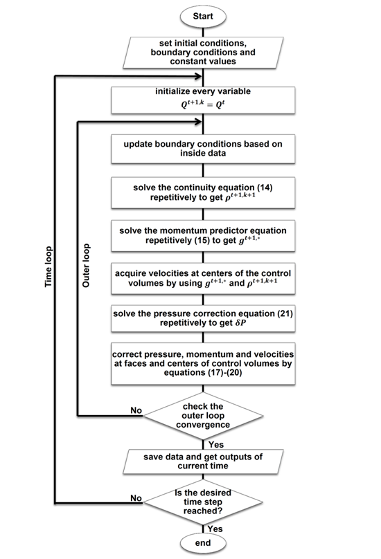
Figure 1 Flowchart of the numerical method.
Applying boundary conditions and geometry
Ghost cells are used to impose boundary conditions. These cells, which extend the computational domain, are a few additional cells on either end that their values are set at the beginning of each iteration based on the boundary conditions and the interior solution.12
For creating solid geometries inside the domain, a criterion is used to discriminate between the fluid cells and the solid cells. During marching of the computational domain, calculation of the governing equations for the solid cells must be ignored. Also, to calculate the adjacent cells of the solid cells, a sub-program imposes the required values of the solid cells, as boundary ghost cells, based on the fluid cells. Figure 2 shows the flowchart of creating solid geometries.
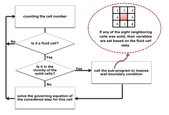
Figure 2 Flowchart of creating solid geometries.
Code validation
For validation, a two dimensional test problem, the supersonic flow through a wind tunnel with a step, is simulated. This problem was introduced in the paper by Emery13 and completely investigated by Woodward & Colella14 later. The tunnel heights and lengths are 1 length unit and 3 length units, respectively. The initial condition is a uniform flow with Mach 3, density
, pressure 1atm and
, which leads to the strong shocks. Also, the step height is 0.2 length units and is located 0.6 length units from the tunnel entrance. The additional boundary conditions near the corner of the step are applied as same as reference14 to minimize numerical errors generated at the corner of the step.
Figure 3 shows the comparison of the density contours for different times with reference14 which indicates remarkable agreement. The dimensionless time is obtained using the length unit and the sound speed.This Figure shows the overexpansion of the flow at the corner of the step and the formation of the lambda shaped shock within the time evolution.
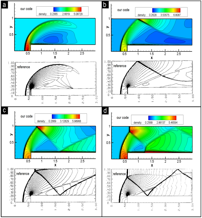
Figure 3 The comparison of the density contours with Reference 14, The CFL number = 1.02, Grid number = 80X240, Dimensionless time = a: 0.5, b: 1.0, c: 2.0, d: 4.0.
Axisymmetric flow
The numerical method for an axisymmetric flow is as same as Section 2 with the exception that the governing equations are as bellow that it ignores circulation
:
(22)
(23)
(24)
(25)
(26)
For validation of the written axisymmetric code, the under-expanded circular jet, which containing Mach disk, is simulated. The jet exit Mach number and the exit static pressure ratio
are 1.5 and 3.15, respectively. The contour in Figure 4 shows the comparison of the obtained Mach number distribution with reference,6 which indicates desirable agreement. A Mach disk is placed at the location of about 4.5 times greater than the jet exit radius from the jet exit location. Also, the radius of the Mach disk is approximately 0.7 times smaller than the jet exit radius. The contour value shows that the Mach number upstream of the Mach disk has accelerated to values about 4.0, but the Mach number downstream of the Mach disk is reduced to values below 0.5.
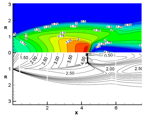
Figure 4 The comparison of the Mach number contour with Reference 6.
The supersonic starting flow interactions with the cross section of a cylinder
The supersonic starting flow jet interactions with a cross section of a cylinder is simulated in which the jet exit Mach number and the exit static pressure ratio are as same as the last Section equal to 1.5 and 3.15, respectively. The radius of the cylinder is two times greater than the radius of the jet exit plane. The cylinder cross section is located at the 4 length units from the jet exit plane. To describe the evolution of the starting flow fields, the Mach number, pressure, density and temperature evolutions are considered.
Figure 5 shows the Mach number evolution. When the jet ejects, Prandtl-Meyer expansion wave is created at the exit. Because of the expansion, gas accelerates to higher Mach number. At first, the flow structure is as like as a typical supersonic under-expanded planar jet, which moves downstream like a mushroom head. However, this mushroom head collides with the cylinder cross section around8ms. The interactions of the acoustic wave and the mushroom head with the rigid body lead to propagate the acoustic waves from the impingement region out and toward the nozzle exit that disrupts the vortex rings structures. In following, it is observed that the Mach disk is formed at the location of about 3 length units from the jet exit plane. Also, another shock wave is commenced to propagate at the cylinder lip.
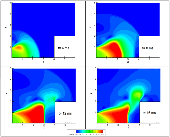
Figure 5 The Mach number evolution.
Where the supersonic gas is accelerated, pressure, density and temperature are decreased (Figures 6-8). Interaction of the mushroom head with the cylinder cross section increased pressure distribution significantly at the time of 8ms. It creates a pressure wave in the opposite direction that reduces the pressure distribution on the cylinder surface at following times. Moreover, the temperature contour shows that by crossing the shock width, temperature increases about two times. The highest temperature on the cylinder cross section surface happens about collision of mushroom head.
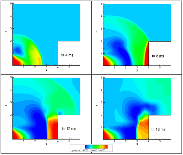
Figure 6 The pressure contour evolution.
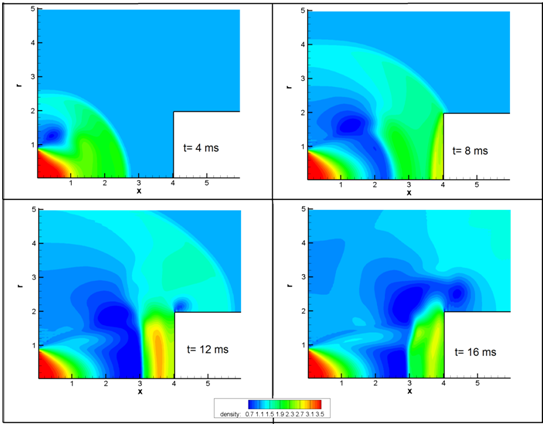
Figure 7 The density contour evolution.
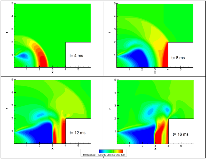
Figure 8 The temperature contour evolution.
Figure 9 indicates the evolution of total force due to jet flow on the cylinder cross section. The highest total force on the cylinder cross section surface occurs just after collision of mushroom head with the surface which is about 2500 kpa. Also, oscillation in the magnitude of total force on the surface is happened in the following times. Figure 10 shows the pressure distribution along the radius of the cylinder cross section surface for different time. It demonstrates reducing in the pressure value in the vicinity of cylinder lip which is evident because of increasing in velocity magnitude adjacent to cylinder lip. In an opposite manner with time of 12ms, depression in the pressure values occurred in time of 8 ms and 16 ms along the surface, which are due to the impacts of vortex rings.

Figure 9 The evolution of total force on the cylinder cross section surface.
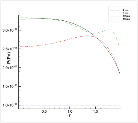
Figure 10 The pressure evolution along the radius of the cylinder cross section.


