Submit manuscript...
eISSN: 2576-4500

Aeronautics and Aerospace Open Access Journal

Research Article Volume 2 Issue 3

On the curvature of reflected diffracted shock wave interacted by an yawed wedge (Subsonic case)

RS Srivastava, Sanjay Srivastava

Formerly of Defence Science Centre, India Bechtel, India

Correspondence: RS Srivastava, Formerly of Defence Science Centre, New Delhi, India

Received: January 24, 2018 | Published: May 9, 2018

Citation: Srivastava RS, Srivastava S. On the curvature of reflected diffracted shock wave interacted by an yawed wedge (Subsonic case). Aeron Aero Open Access J. 2018;2(3):113-117. DOI: 10.15406/aaoaj.2018.02.00040

Download PDF

Abstract

Lighthill considered the diffraction of normal shock wave past a small bend of angle d. Srivastava and Srivastava and Chopra extended the work of Lighthill to the diffraction of oblique shock wave (consisting of incident and reflected shock wave). Chopra and Srivastava further carried forward their work when the diffraction of oblique shock wave takes place with yawed wedges. In the present investigation curvature of the reflected diffracted is obtained when the interaction takes place with yawed wedge and the relative outflow behind reflected shock wave before diffraction is subsonic.

Keywords: curvature, diffraction reflection, yawed wedge, subsonic.

Introduction

Lighthill1 considered the diffraction of a normal shock wave past a small bend of small angle d. The analogous problem of a plane shock wave hitting the wall obliquely together with the reflected shock has been solved by Srivastava2 and Srivastava & Chopra.3 Srivastava2 solved the problem when the relative outflow behind reflected shock before diffraction is sonic and subsonic. Srivastava & Chopra3 solved the problem when the relative outflow behind the reflected shock wave before diffraction is supersonic. Srivastava4 gave the results concerning curvature of the reflected diffracted shock when the relative outflow behind the reflected shock before diffraction is sonic; subsequently he solved the curvature of reflected diffracted shock5 when the relative outflow before diffraction is subsonic. Chester6 considered the problem of reflection and diffraction of normal shock wave interacted by yawed wedges which was the extension of Lighthill’s1 problem of diffraction of a normal shock wave past a small bend. The results of Srivastava2 and Srivastava & Chopra3 have been extended results to the case of yawed wedges Chopra & Srivastava.7 More specifically the attempt is concerned with the interaction of an oblique shock configuration (consisting of incident and reflected shock) with an yawed wedge i.e. the shock line (line of intersection of incident and reflected shock) makes some non zero angle with the leading edge of the wedge. In the present case curvature results have been obtained for the yawed case when the relative outflow behind reflected shock before diffraction is subsonic.

Mathematical formulation

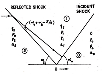
Let the velocity pressure, density and sound speed ahead of the shock wave be denoted by o, p0, ρ0, a0o, p0, ρ0, a0 in the intermediate region by q1, p1, ρ1,a1q1, p1, ρ1,a1 and behind the reflected shock by q2, p2, ρ2,a2q2, p2, ρ2,a2 . Let U denote the velocity of intersection of the incident and reflected shock, δ the angle of the bend, α0α0 is the angle of incidence and α2α2 is the angle of reflection. The Rankine-Hugoniot equation across incident and reflected shock forγ=1.4γ=1.4  (g being the ratio of specific heats are gives as follows Srivastava.8,9 Across the incident shock (Figure 1).

q1=56Usinα0(1a20U2sin2α0)q1=56Usinα0(1a20U2sin2α0)   (1)

p1=56ρ0(U2sin2α0a207)p1=56ρ0(U2sin2α0a207)     (2)

ρ=6ρ0(1+5a20U2sin2α0)ρ=6ρ0(1+5a20U2sin2α0) 

a0=γp0ρ0a0=γp0ρ0   (3)

Across the reflected shock

ˉq2=ˉq1+56(U*ˉq1)(1a21(U*ˉq1)2)¯q2=¯q1+56(U¯q1)(1a21(U¯q1)2)     (4)

p2=56ρ1{(U*ˉq1)2a217}p2=56ρ1{(U¯q1)2a217}    (5)

ρ2=6ρ11+5a21(U*ˉq1)2ρ2=6ρ11+5a21(U¯q1)2       (6)

Where ˉq2=q2sinα2,¯q2=q2sinα2,ˉq1=q1cos(α0+α2)¯q1=q1cos(α0+α2)

U*=Usinα2,U=Usinα2, a1=γp1ρ1a1=γp1ρ1 

Also we have

q1cosθ=q2cosα2,θ=α0+α2π2

As the oblique shock configuration advances over a yawed wedge (shock line making some non zero angle with the leading edge of the wedge) the velocity of the point of intersection of the leading edge and shock line moves with velocity Ucosecχ , U being the velocity of shock line and χ being the angle of yaw (Figure 2).

By superimposing a velocity on the whole field in a direction opposite to the direction of motion of the point of intersection of the shock line and the leading edge, the shock configuration becomes stationary and the resulting velocity behind the reflected shock for stationary configuration say V2 is given by

V22=U2cosec2χ+q222Uq2    (7)


For conical field flow to occur behind the reflected shock V2a2 should be greater than 1 which from (7) gives the condition that we should have

sin2χ<U2a22+2Uq2q22    (8)

We have also the relation

tanμ=Uq2Ucosecχ     (9)

Further the semi angle of the Mach cone is given by

sinα=a2V2       (10)

Let the disturbed flow variable behind the reflected diffracted shock referred to Ox'y'z' axes be denoted by

V2=(u2, v2,V2+w2), p'2, ρ'2, S'2      (11)

where u2, v2,w2 are small perturbation in the velocity along 0x, 0y' 0z' and respectively,p'2 is the pressure,p'2 ρ'2 is the density andS'2 is the entropy. Using conservation laws we obtain the flow equations as

V'2p'2+ρ'2V'2=0     (12)

(V'2)V'2+1ρ'2ρ'2=0    (13)

V'2S'2=0     (14)

We introduce the following transformations

x=x'z'tanαM

x=x'z'tanα   

p=p'2p2a2ρ2q2        (15)

ρ=a2(ρ'2ρ2)ρ2q2

u=u2q2cosα

v=V2q2cosα

w=W2q2sinα

(xx+yy+1)(xpx+ypy)=2px2+2py2   (16)

The characteristics of equation (16) are tangents to the unit circle x2+y2=1 which in 0x'y'z' axes becomes the cone x'2+y'2=z'2tan2α. The region of disturbance will therefore be bounded by cone of disturbance, the shock front and the wall of the wedge (Figure 3).

The position of the shock line referred to (x,y) system is vand it will lie inside on the cone of disturbance and outside the cone of disturbance according as

tanμtanα1   (17)

and tanμtanα>1    (18)

Following Chopra & Srivastava,7 the undisturbed part of the reflected shock lies in the plane

x=kycotα2secμ , k=tanμtanα  (19)

The equation of the reflected diffracted shock may therefore be written as

xtanα=tanμycotα2secμtanα+f(y)secμ     (20)

where f(y)is small


The radius of curvature κ is given by

κ    (21)

Using equation (20), we obtain

κ=f(y)cotα2cotαsec2μ(1+cot2α2sec2μ)32    (22)

Following Srivastava,7 we have

κ=f(y)cotα2cotαsec2μ(1+cot2α2sec2μ)32    (23)

Equation (23) gives

f''(y)=vy.1(C1B1y)   (24)

Combining (22) and (24) we have

κ=vy1(C1B1y)×sec2μcotαcotα2(1+cot2α2sec2μ)32   (25)

Following Srivastava2 and Srivastava & Chopra3 we have

vy=C1B1yC3B3ypy    (26)

From (25) and (26) we have

κ=1C3B3y pysec2μcotαcotα2(1+cot2α2sec2μ)32     (27)

We have the relation

y=κ{cosϕ+sinϕtanθ} ,κ=Uq2a2sinα2   (28)

and cotϕ=cotα2secμ

tanθ=κκ(Z21)(Z2+1) , κ=1κ2    (29)


Following Chopra10 and Srivastava11 the relation between Z and z1 is given by

z1=12[(bz+1bz1)πλ+(bz+1bz1)πλ]     (30)

where b=(κsinϕ+κcosϕκsinϕκcosϕ)12

and λ=cot1(cotϕ(sin2ϕκ2)12)

From (30) we obtain

z=1b{1+(z1+z211)λπ}{1(z1+z211)λπ}     (31)

In (28)z is substituted in terms of z1 actually in terms of x1 as on the real axis y1=0,,z1being equal to z1 , we will then obtain dydx1.

The numerical values for the calculation are

p0p1=0,   α0=39.970,    χ=400

These data provide Uq2a2=0.94699 (subsonic)

The solution of the problem is obtained by the introduction of the complex function

ω(z1)=px1ipy1   (32)

ω(z1) is given by Chopra10

ω(z1)=Gδ[H(z1x0)1]cosχsecα(z1x0)(z211)12(z11)βπ  eϕ+iβ    (33)

where

ϕ=z112π[1.51716β1+4(0.00505β)(10.25z1)+2(0.10311β)(10.50z1)+4(0.22845β)(10.75z1)+(1.57080β)(1z1)]   (34)

β=tan1{(py1)(px1)}x1=t=1x=z1  (35)

(py1)(px1)=0.169310.09429tanθ0.05812tan2θ+0.02859tan3θ(0.756070.24393tan2θ)12×(0.36323+0.11275tanθ0.06569tan2θ)   (36)

The curvature κfrom (27) can be put in the form

κ=1C3B3ypx1x1ysec2μcotαcotα2(1+cot2α2sec2μ)32   (37)

On the shock from z1=x1+iy1=x1 (z1=x1+iy1=x1 being zero) and varies from x1=1 to x1= .

The real part on the right hand side of 33 with z1 replaced by x1 gives the value of px1 .

As mentioned earlier dydx1 is obtained from (28). Now that px1 is known and dydx1 is known then from (37) κ is known. We therefore have obtained final expression for κ .

We have the relation tanθ=κκ (z21)(z2+1) when z,  tanθ=κκ  .

So from the relation (28)y=κ(cosϕ+sinϕκκ )=κcosϕ+κsinϕ

So y(κcosϕ+sinϕ κ')=1

when y(κcosϕ+sinϕ κ')=1 , then we have

tanθ=κκ  (1b2)(1+b2)=cotϕ

We have then y=κ{cosϕ+sinϕ(cotϕ)}=0

ory(κcosϕ+sinϕ κ')=0  

So in the final analysis z (z11 i.e. x11 )

y(κcosϕ+ κ'sinϕ)=1  

and z11b (z1,   x1)   

y(κcosα+ κ'sinϕ)=0 

Figure 1 Oblique shock configuration.
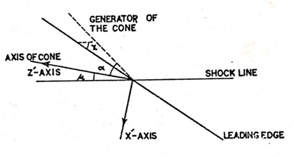
Figure 2 Configuration after interaction in the x′-z′ plane
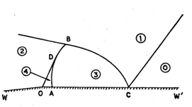
Figure 3 Flow picture in a plane perpendicular to the axis of the cone of disturbance.

Numerical analysis

Taking px1 into consideration from equation (33) it could be seen that κ is zero at x1=1  (see equation 38) i.e. at the point of intersection of shock and Mach Cone. This is physically consistent. Also at x1, κ tends to i.e. at the point of intersection of wall surface of the wedge and shock front intersection.

Referring to equation (33) we see that the point of inflexion over the curvature of the reflected diffracted shock is given by when

H(x1x0)1=0     (38)

i.e. when

x1=x0+1H    (39)

From the calculation we have (Chopra10)

x0=0.75595  and H=0.51062

with these values of x0 and H we obtain from (39)

x1=2.71935

This indicates that at x1=2.71935 , we find that there is a point of inflexion over the reflected diffracted shock. The curvature has infinite value, then it passes through point of inflexion and finally it becomes zero. This is the qualitative estimate of the curvature.

Conclusion

The results obtained here give more general results as intersection is considered with yawed wedges. The results when there is no yaw in the wedge will reduce to the results of paper (2). The results are general and could be used in aeronautics depending on the situations that arise.

Acknowledgement

None.

Conflicts of Interest

The authors declare that there is no conflict of interest.

References

Creative Commons Attribution License

©2018 Srivastava, et al. This is an open access article distributed under the terms of the, which permits unrestricted use, distribution, and build upon your work non-commercially.