The set of equations describing non-stationary adiabatic motions of compressible medium in general coordinates
, includes the following equations:2
- Continuity equation
(1)
- Motion equation
(2)
Where
- Energy equation
(3)
Where
is components of mass force vector;
- Christoffel symbols;
- contravariant components of symmetric stress tensor; E- specific internal energy;
- components of symmetric strain velocity tensor:
- density of medium;
- velocity vector;
- components of acceleration vector;
(4)
Behavior of materials under study both metal and concrete has been described by elasto-plastic model.
Stress tensor is presented as a sum of deviatoric
and spherical part P :
(5)
where
- metric tensor. Pressure inside the materials has been calculated using Mie-Gruneisen equation as a function of specific internal energy E and density
:
(6)
where
- material constants,
- initial specific volume, V- current specific volume.
Suppose that the principle of minimum work of true stresses on the increments of plastic deformations is true for the medium, than the connection of component of strain velocity tensor and stress deviator is as follows:
(7)
In this case time derivatives of stress tensor are accepted by Jaumann definition:
where
, G- shear modulus.
Consider that material behaves in elastic manner (
), in case when Von Mises criterion is followed:
(8)
and it behaves in plastic manner (
), when the criterion is not followed. Here
- dynamic tensile yield stress that can in the general case be the function of deformations velocity, pressure and temperature. The dependency of yield stress on the pressure has been considered for concrete:3
(9)
In case the condition (8) is violated, we apply the procedure of correction of stresses considering the material plasticity for calculation of the component of stress deviator. Components of
are multiplied by normalizing factor, that equals to description of medium behavior in plastic zone as proved by equations of Prandtl-Reuss.
Limiting value of plastic strain intensity is accepted as a local criterion of shear fracture in metals:
(10)
Where T1,T2 -first and second invariants of strain tensors.
To describe concrete fracture we use Hoffman criterion.4 The criterion considers the differences in ultimate tensile and compressive strength:
(11)
where
is defined from the following formulas:
Where
- ultimate strength along axes X,Y,Z under tension and compression respectively, while
-ultimate shear strength along the corresponding axes. In case of isotropic material
,
,
.
It is suggested that concrete fracture in conditions of intensive dynamic loads occurs the following way 1:
- In case strength criterion (11) is violated under conditions of compression
, than further material behavior is described by hydrodynamic model, in that case concrete can be destructed when satisfying the criterion considering the ultimate value of plastic deformations intensity (10);
- In case criterion (11) is violated under conditions of tension
, than material is considered to be completely destructed and components of stress tensor are supposed to be equal to zero.
Experiments have shown that dynamic loads lead to increasing strength properties of concrete.5 Moreover the dependency of ultimate tensile and compressive strength differs. Connection of static and dynamic ultimate strength is expressed by means of dynamic response factor:
where
- dynamic strength,
- static strength.
Based on the experimental data dynamic response factor has been obtained for concrete under compression (12) and tension (13). Corresponding curves are given in Figure 1, where curve 1 describes dependency of dynamic response factor under tension on deformations velocity, curve 2 describes dependency under compression.
(12)
(13)

Figure 1 Dependency of ultimate strength of concrete on deformation velocity: 1 - under tension, 2 -under compression.
Ultimate shear strength of concrete is defined from the values of ultimate compressive and tensile strength:3
Important aspect while numerical modeling of impact interaction is selecting the algorithm of contact boundaries calculation. Generally, the existing program software use algorithms “element-node” and “node-node” to define the possible penetration of one body into another. The given work suggests the algorithm of “element-element” type,6 proved oneself to be appropriate while solving the three dimensional objectives and enabling to use possibilities of parallel computing to a maximum extent.
The results of numerical simulation of ogival projectile interaction with reinforced concrete barrier are given below. The properties of the investigated materials are given in Table 1. The projective is given as a shell made from titanium and filled with explosive substance. The thickness of reinforced concrete barrier is 1 m. Layers of reinforcement are placed close to front and back surfaces of the barrier. The initial projectile velocity is 300 and 700 m/s. Two types of interaction have been considered: the standard one, and under the angle of 5 degrees to normal line.
Material |
|
Speed of
Sound Cs, m/s |
Poisson's
Ratio |
Tensile
Strength, MPa |
Compressive
Strength, MPa |
Young's
Modulus Е,
Gpa |
Concrete |
2450 |
4500 |
0,2 |
1,75 |
22 |
26 |
Titanium |
4500 |
6900 |
0.32 |
400 |
400 |
146 |
Steel |
7850 |
5930 |
0,3 |
400 |
400 |
204 |
Table 1 Properties of materials
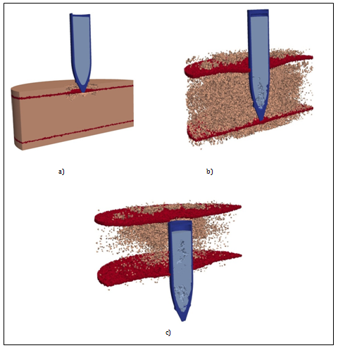
Figure 2 shows in section the standard penetration of projectile with initial velocity of 700 m/s. The areas of reinforcement in the barrier are marked in red color. Through penetration of barrier and concrete fracture has been observed. Concrete is destructed due to the action of tensile stresses. Because of low tensile strength of concrete it is destructed almost through the entire surface. One can also note destruction of explosive substance close to the projectile nose in the central area. Destruction of explosive substance is conditioned by the action of unloading wave distributed from the lateral surface of projectile. In this case titanium shell is deformed insignificantly almost completely saving its initial shape.

Figure 2 Configuration of projectile and barrier.
degrees. A) t=0.2 ms, B) t=1.2 ms, C) t=3 ms.
Figure 3 shows normal penetration of projectile with the velocity of 300 m/s. In general the fracture pattern is similar to Figure 2. Larger level of destruction in the barrier and the explosive substance is conditioned by longer process of interaction thus it has lead to the moment of barrier striking (Figure 3C) and larger damage cumulation.

Figure 3 Configuration of projectile and barrier.
.A) t=0.5 ms, B) t=3 ms, C) t=6 ms.
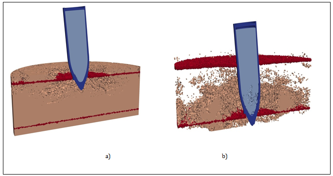
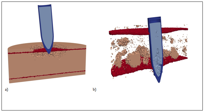
(Figure 4) (Figure 5C) show computation configuration of the projectile and barrier by interaction under angle of 5 degrees for the initial velocities of 300 and 700 m/s, correspondently. The same as for normal interaction (Figure 2 (Figure 3) one can observe consistent reinforced concrete barrier striking. When impacting under angle localization and geometry of destruction areas as well as destruction in explosive substance is changed. The areas of destruction in the explosive substance are formed not only in the central part of the projectile but also close to the titanium shell in the nose part on the right (Figure 4B) (Figure 5B). This can be explained by the fact that during impact under angle this part of projectile is free at the initial moment of interaction, thus the unloading wave is being formed here, further leading to tensile stresses occurrence which destruct explosive substance.

Figure 4 Configurations of projectile and barrier.
. Time periods A) t=0.5ms, B) t=1.5ms.

Figure 5 Configurations of projectile and barrier.
. A) t=0.7ms, B) t=4.6ms.


