eISSN: 2576-4500


Short Communication Volume 7 Issue 2
Department of Chemical, Materials and Industrial Production, University of Naples ‘Federico II’, Italy
Correspondence: Fabio Scherillo, Department of Chemical, Materials and Industrial Production Engineering, University of Naples ‘Federico II’, Italy
Received: April 19, 2023 | Published: May 2, 2023
Citation: Scherillo F, El-Hassanin A, Squillace A. Metallurgical aspect of a joint made of Inconel 718 and CuCrZr brazed with Ag-Cu eutectic filler. Aeron Aero Open Access J. 2023;7(2):47-50. DOI: 10.15406/aaoaj.2023.07.00169
The realization of bimetallic structures is one of the major challenges of manufacturing industry, to this aim different technologies are employed, among these vacuum brazing presents some advantages: this technology, in fact, is relatively easy to use and the relative low temperature and low process time employed, avoid the formation of brittle intermetallics and thermally affected zones. An application of vacuum brazing technology is the realization of regenerative thrust chamber for rocket engines where cooling channels of CuCrZr are joined to Inconel 718 combustion chamber. In this work the critical metallurgical aspects occurring during brazing of Inconel 718 and CuCrZr using eutectic Ag-Cu filler are described in detail. These aspects include the formation of two distinct metallurgical zones inside the filler and an interdiffusion zone with Kirkendall porosity at the interface Inconel 718-Brazing Alloy. The analysis of fracture surface after tensile tests indicates that the interdiffusion zone is the weak point of the joint.
Keywords: Inconel 718, CuCrZr, brazing, CuSil
In manufacturing industry, the realization of reliable bimetallic structures is a major goal. The use of multi-metal components could lead great advantage, for example the corrosion and wear resistance can be significantly improved using functionalized metallic coating. Other applications consist in complex components made of two structural alloys, where, the joining technology plays the most important role. Different manufacturing methods are available such as conventional welding,1 diffusion bonding,2 linear friction welding,3 friction stir welding4 and brazing.5
In some applications there is the necessity to couple a high strength alloy with an alloy with high thermal conductivity. An example is the realization of regenerative rocket engines, where, on the combustion chamber made in Inconel 718, cooling channels made in CuCrZr could be brazed. For instance, the thermal conductivity of Inconel 718 is 11.4 W/(m•K) and 320 W/(m•K) for CuCrZr. Regenerative thrust chamber manufacturing is still a bottleneck in the design and development of rocket engines and several manufacturing methods were proposed worldwide e.g., vacuum brazing, diffusion bonding, laser beam welding, ultrasonic welding, electroplating, additive manufacturing, thermal spray, centrifugal casting etc. Vacuum brazing is a technique used for a very long time in the aerospace field and presents some advantages: alloys with a great difference in melting point can be joined, the process temperature and the time employed being low enough to avoid the formation of brittle intermetallic phases and thermally affected zones. The possibility to have an accurate control on the various process parameters is another very attractive advantage. In fact, the employment of well-positioned thermocouples and manometers allows accurate monitoring of the thermal cycle and the pressure profiles in the brazing furnace. Furthermore, brazing joints are relatively easy to make, and the process is suitable to be automated.6 In this work the metallurgical phenomena occurring during the brazing of a joint made of Inconel 718 and CuCrZr using Ag-Cu filler, are described, focusing the attention on their influence on the tensile resistance of the joint.
The brazed specimen made of Inconel and CuCrZr have been realized with metallic plates of 14 mm thickness. The composition of the two alloys is reported in Table 1.7 The brazing filler is a eutectic Ag-Cu alloy (Ag 72 wt%, Cu 28 wt%). The dimensions of the brazed joints are reported in Figure 1a.
|
Ni |
Cr |
Fe |
Mo |
Nb |
Ti |
Al |
Zr |
Cu |
|
|
(wt%) |
(wt%) |
(wt%) |
(wt%) |
(wt%) |
(wt%) |
(wt%) |
(wt%) |
(wt%) |
|
|
Inconel 718 |
50-55 |
17-21 |
Bal. |
2.80-3.30 |
4.87-5.20 |
0.65-1.15 |
0.20-0.80 |
- |
- |
|
CuCrZr |
- |
1 |
- |
- |
0.1 |
Bal. |
Table 1 Chemical composition of Inconel 718 and CuCrZr
In order to promote the adhesion before the brazing process, the metallic plates have been grinded with emery paper to P 2400 grade and then pickled to eliminate the thin oxide layers on the surface. The pickling solution is made of HNO3 and HF for Inconel, and of H2SO4 for CuCrZr. The brazing process has been done in a vacuum furnace following the thermal cycle of 6 steps reported below:
The thrust chamber can be ideally considered made of two coaxial cylinders, the outer made in Inconel and the internal one in CuCrZr, during heating and cooling cycles the difference in thermal expansion coefficient and thermal conductivity of the two alloys leads to loads on the two metals, the main component of this loads is along the radius. Tensile tests on butt joints reproduce more accurately the stress condition of the thrust chamber. CTE and thermal conductivity of the two alloys are reported in Table 2.7
|
Inconel 718 |
CuCrZr |
|
|
Thermal Conductivity (W/m·K) |
11.4 |
330 |
|
CTE (10-6/K) |
13 |
18 |
Table 2 Thermal conductivity and CTE of Inconel 718 and CuCrZr
Specimen for tensile test have been obtained from the brazed joints, the test has been done using an MTS Alliance RT/50 machine with a deformation rate of 0.5 mm/min. The dimension of the tensile specimen is reported in figure 1b. The images of the surface fracture have been acquired using an Olympus SZ-PT stereomicroscope. Another specimen has been used for metallographic analysis, to this aim the sample have been mounted in hot epoxy resin and then polished to mirror like finishing using firstly a P400 emery paper and then 9 µm, 3 µm and 1 µm diamond suspension. The polished samples have been analyzed by means a Hitachi TM 3000 Scanning Electron Microscope (SEM) coupled with an Oxford Instrument silicon swift detector used for Electron Probe Microanalysis (EPMA), to this aim The Kα lines of Cu, Ag, Ni, Fe and Cr have been generated operating at 15 kV. The EPMA analysis has been performed also on the surface fracture to better understand the rupture mechanisms.
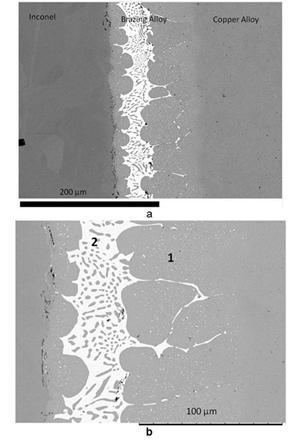
Figure 2a shows a micrograph of the joint, where the CuCrZr, Brazing Alloy and Inconel are well distinguishable. More in details, (Figure 2b), inside the Brazing Alloy two zones are evident. Zone 1 is made of a copper matrix with silver rich precipitates, and the composition of this zone is richer in copper to respect the eutectic composition of the alloy employed in the brazing process (Table 2).

Figure 2a Global view of the brazed joint; 2b Details of the solidified brazing alloy with the different zones.
Zone 2 has the typical microstructure of solidified eutectic. In order to explain these differences, the phenomena occurring during the fusion and solidification of the Brazing Alloy are described in the following. During the brazing process, the brazing liquid alloy gets richer in copper due to partial dissolution of the CuCrZr alloy. In this way its composition moves away from the eutectic one. The subsequent solidification of the Brazing Alloy is directional; the solidification process begins at the interface with CuCrZr where, due to the high thermal conductivity of the copper alloy, the cooling rate is the highest. The solidified front moves towards the Inconel and the residual liquid becomes richer in the component with the lower melting temperature, i.e. Ag. When the residual liquid reaches the eutectic composition, the transformation L→α+β occurs very quickly, where α is a solid solution of Ag in Cu and β a solid solution of Cu in Ag.8
In Figure 2b α and β phases are easily distinguished, the white precipitates are the β phase, the darker matrix is theα phase. This interpretation is confirmed by the measured composition of the two phases reported in Table 3.
|
Element |
Zone 1 |
α |
β |
|
Copper (wt%) |
91.3 |
94.5 |
10.4 |
|
Silver (wt%) |
8.7 |
5.5 |
89.6 |
Table 3 Chemical composition of Zone 1, dark matrix (α phase) and white precipitates (β phase) in figure 2b
In Figure 3 the concentration profiles of Cu and Ag at the interface Brazing Alloy-CuCrZr is reported. This interface cannot be easily distinguished from the micrographs; however, the profiles present a discontinuity, therefore the discontinuity zone in the composition curves can be considered as the interface.

Figure 3a Interface between brazing alloy and copper alloy; 3b Concentration profile of Cu and Ag among the interface.
Furthermore, in the Ag-Cu binary system, silver easily diffuses inside copper,9 however the penetration of silver inside the copper alloy is limited by its low solubility. On the right side of the interface the concentration of Ag is above its solubility in α phase and that explain the presence of the white precipitates of β phase, on the left side the Ag concentration is below, and the precipitates are absent.
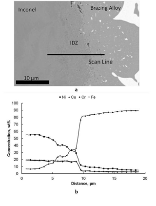
In Figure 4 the concentration profiles of Cr, Cu, Fe and Ni at the interface Brazing Alloy-Inconel are showed. This interface is characterized by the presence of an Interdiffusion Zone (IDZ) in which Ni diffuses from Inconel to Brazing Alloy and its concentration decreases with respect to the parent alloy. Cu diffuses from Brazing Alloy to Inconel and its percentage is lower compared to the filler. In the same zone we observe that the concentrations of Cr and Fe do not change substantially with respect to Inconel. Cr and Fe are insoluble in Cu10,11 so they do not penetrate inside the Brazing Alloy. The IDZ is characterized by the presence of two diffusing elements, i.e. Cu and Ni, and two non-diffusing elements, i.e. Cr and Fe, that leads to unbalanced diffusive flows that generates the Kirkendall porosity well evident in Figure 4a.12

Figure 4a Interface between Inconel and brazing alloy with the IDZ; 4b Concentration profiles of Ni, Cu, Cr and Fe among the interface.
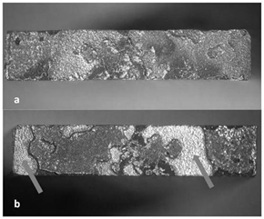
The IDZ plays a key role in the mechanical behavior of the joint. In Figure 5 the fracture surface of the joint is showed; on the Inconel side two zones can be distinguished, the initiation zone, pointed by arrows, and the propagation zone. The Sem morphology of the propagation zone is reported in figure 6a, the composition of this zone (Table 4) is compatible with the Zone 2 reported in Figure 2b, more in details the fracture is ductile with the classical dimples. The Figure 6b shows a detail of the fracture surface with the boundary between the initiation zone (in the lower side of figure) and propagation zone (the upper side). The EPMA analysis performed on the initiation zone indicates a composition comparable with the IDZ described above. The IDZ is the weak point of the joint: the ultimate tensile load has a value of 130 MPa, the expected value is about 200 MPa.

Figure 5 Fracture morphology after the tensile test. 5a CuCrZr side of the joint; 5b Inconel side of the joint; The arrows indicate the initiation zones.
|
Element |
Weight % |
|
Nickel |
32.4 |
|
Copper |
38.9 |
|
Chromium |
14.6 |
|
Iron |
14.1 |
Table 4 Chemical composition of the fracture initiation zone
In conclusion the use of Ag-Cu eutectic brazing alloy to join Inconel 725 and CuCrZr alloys presents some critical aspect:
None.
The author declares that there is no conflict of interest.
None.

©2023 Scherillo, et al. This is an open access article distributed under the terms of the, which permits unrestricted use, distribution, and build upon your work non-commercially.