Submit manuscript...
eISSN: 2576-4500

Aeronautics and Aerospace Open Access Journal

Review Article Volume 4 Issue 3

Linear controllers for free-flying and controlledfloating space robots: a new perspective

Amr Mohamed,1 Chakravarthini Saaj,2 Asma Seddaoui1

1University of Surrey, UK
2University of Lincoln, UK

Correspondence: Amr Mohamed, University of Lincoln, Lincoln, LN6 7TS, United Kingdom

Received: June 12, 2020 | Published: July 29, 2020

Citation: Mohamed A, Saaj C, Seddaoui A. Linear controllers for free-flying and controlled-floating space robots: a new perspective. Aeron Aero Open Access J. 2020;4(3):97-114. DOI: 10.15406/aaoaj.2020.04.00112

Download PDF

Abstract

Autonomous space robots are crucial for performing future in-orbit operations, including servicing of a spacecraft, assembly of large structures, maintenance of other space assets and active debris removal. Such orbital missions require servicer spacecraft equipped with one or more dexterous manipulators. However, unlike its terrestrial counterpart, the base of the robotic manipulator is not fixed in inertial space; instead, it is mounted on the base-spacecraft, which itself possess both translational and rotational motions. Additionally, the system will be subjected to extreme environmental perturbations, parametric uncertainties and system constraints due to the dynamic coupling between the manipulator and the base-spacecraft. This paper presents the dynamic model of the space robot and a three-stage control algorithm for this highly dynamic non-linear system. In this approach, feed-forward compensation and feed-forward linearization techniques are used to decouple and linearize the highly non-linear system respectively. This approach allows the use of the linear Proportional-Integral-Derivative (PID) controller and Linear Quadratic Regulator (LQR) in the final stages. Moreover, this paper covers a simulation-based trade-off analysis to determine both proposed linear controllers' efficacy. This assessment considers precise trajectory tracking requirements whilst minimizing power consumption and improving robustness during the close-range operation with the target spacecraft.

Research highlights: orbital space robotic missions, control of space robots, free-flying and controlled-floating modes of operation, application of linear controllers

Keywords: space robot, in-orbit operation, robotic manipulator, linear controller, free-flying, controlled-floating

Introduction

Modern small satellites have revolutionized the economics of space, making it more affordable.1 With advances in space technology, there is a growing interest to use robots for in-space services. Space robots offer several benefits, including but not limited to: the disposal of orbital debris or faulty spacecraft, extending the life of high-value assets such as the International Space Station (ISS) or the Hubble Space Telescope (HST), refuelling and repairing of commercial spacecraft, including mega constellations, as a more economical alternative.2,3 Extending the life of such space systems and reducing the associated costs will require capture, repair, maintenance, and assembly capabilities in orbit. Currently, these servicing tasks are being accomplished manually by astronaut through Extra Vehicular Activity (EVA). However, time restrictions for manoeuvring, the cost of human life support facilities, and the high risks astronauts face are some severe restrictions for EVA.4 Additionally, beyond Low Earth Orbit (LEO), high-value satellites occupy valuable orbital slots where any faulty ones represent a threat for operational spacecraft in Medium Earth Orbit (MEO) or Geostationary Orbit (GEO). Moreover, the presence of humans is currently not possible in higher Earth orbits due to extreme environments.5 Other benefits of using space robots are reducing design, manufacturing, and launch costs by approximately $20,000/Kg.6 Moreover, space robots offer technology upgrading, in which specific components such as onboard electronics or processors can be periodically upgraded.

Alongside innovation, sustaining space operations and protecting the ecosystem of space is important. However, after 60 years of uncontrolled debris proliferation and intensive space use, Earth orbits now have reached a shifting point, known as the “Kessler syndrome”, where human intervention is needed.7 A forecast for the next 200 years states that access to space would almost be impossible if measures to mitigate space debris proliferation is not in place. Therefore, several solutions have been proposed, including electrodynamic tethers, Earth-based pulsed laser, or even capturing debris using harpoons and nets.7 Considering the limitations of these approaches, space robot controlled by teleoperation have been proposed. However, for high Earth orbit spacecraft, Earth-based teleoperation involves significant time delays because of signal transmission and routing and can take from one to six seconds. The magnitude of these time delays is known to impede teleoperation performance. For a typical teleoperation, even small delays of ~10s-100s of milliseconds lead to an unstable force-feedback system.4 Considering the limitations of these approaches, space robot might be a better alternative for undertaking a wide range of services in orbit.7 However, unlike Earth-based manipulators, the base of the space manipulator is no longer fixed in the inertial space. This introduces a high level of kinematic and dynamic complexity making it more challenging to control the space robot. Moreover, due to the mutual dynamic coupling between the base-spacecraft and the manipulator, reaction forces and moments will be generated during the motion of the manipulator. This is in addition to the issues caused by excitation of vibration of the solar paddles on-board. The severity of these effects depends on the mass ratios between the manipulator and the base-spacecraft; therefore, a threshold of up to one third is when these effects become more dominant. Furthermore, the space robot must be accommodated within the fairing of the launch vehicle. Therefore, presenting significant limitations on the volume, size and design of the robotic arm. The largest robotic arm used was less than 5m available diameter, even the larger launchers such as NASA’s SLS Block 2 and Blue Origin’s New Glenn will be restricted to 8.4m and 7m respectively in the fairing diameter.8 Additionally, the centre of mass of the overall system changes continuously during the manipulator's motion,4 and the system will be subjected to external environmental perturbations like the gravity gradient, aerodynamic drag, solar pressure, residual magnetic disturbances as well as internal parametric uncertainties. Hence, it is challenging to develop a high-performance controller, with sufficient robustness, to withstand all the aforementioned disturbances.

This paper is organized as follows: Section 5 gives a review of the current state-of-the-art of orbital space robots and a detailed explanation of the different modes of operation of a space robot, highlighting the pros and cons of each mode of operation. Section 6 then establishes the mathematical model of the dynamics and kinematics of a controller-floating space robot. Section 7 gives a breakdown of the external perturbations resulting from the space environment, as well as the effects of parametric uncertainties on the system. Section 8 illustrates the control algorithms used for the trajectory tracking of the manipulator’s end-effector and Section 9 discusses the simulation results. It presents a trade-off analysis between PID and LQR controllers to determine their suitability in the final stage of the algorithm implementation. Finally, the main conclusions drawn and open questions for future research are stated in Section 10.

State-of-the-art on space robots

Modes of operation

Traditionally, there are two major approaches for operating a space robot: one links the Attitude and Orbit Control Subsystem (AOCS) of the base-spacecraft with the manipulator's controller, while the other allows the base-spacecraft to move freely in reaction to the manipulator's motion. They are called Free-Flying and Free-Floating configurations respectively.7 In the Free-Flying approach, the controller of the base-spacecraft tries to maintain a constant attitude and position. Therefore, the base of the manipulator can be considered as being fixed in inertial space; thus, all the angular characteristics are similar to its Earth-based counterpart. Accordingly, the rotational matrix of the composite 4x4 Denavit-Hartenberg matrix will have the same format as in the terrestrial manipulator. However, the spacecraft bus platform has to employ excessive attitude control using Reaction Wheels (RWs) or thrusters to maintain almost constant position and attitude during the operation of the manipulator. Such systems have a high level of redundancy and versatility on the one hand, but a limited workspace on the other hand. Moreover, this method avoids any dynamic singularities associated with the uncontrolled attitude of the base-spacecraft, thus, allowing the end effector's orientation and position to be a unique function of the manipulator's joint angles independently of the history of the joint's trajectory.6 On the other contrary, in the Free-Floating approach, the AOCS is turned off to conserve on-board fuel. This means that the position and attitude of the base-spacecraft are not actively controlled during the capturing motion of the manipulator. As a result, the base-spacecraft will move freely in response to the manipulator's motion, hence, introducing holonomic and non-holonomic kinematic constraints.6 Furthermore, Free-Floating systems are characterized by unpredictable dynamic singularities in the workspace of the manipulator. This is due to changing the attitude of the base-spacecraft at which point they become unstable.9 Dynamic singularity is a function of both the manipulator's kinematics as well as dynamic properties, such as the masses and inertia of both the base-spacecraft and the manipulator. Therefore, the attitude of the spacecraft becomes dependent on the path history of the manipulator due to its non-holonomic nature. Moreover, if the attitude of the base-spacecraft is not being controlled, the reachable path independent workspace by the manipulator becomes significantly smaller than the constrained workspace available to the Free-Flying approach.10

To arrive at a more detailed classification of spacecraft manoeuvring modes, Wilde et al.,11 proposed adding three sub-modes, thus fully covering all possible spacecraft manoeuvres within the Free-Flying and Free-Floating modes. These new modes of operation are defined for an isolated spacecraft-manipulator system operating in absence of friction and pure weightlessness. According to Wilde et al.,11 the Free-Floating mode is decomposed into the Floating and Rotation-Floating modes. The former controls only the manipulator’s joints while leaving the 3 Degrees of Freedom (DOF) of the orientation of the base-spacecraft and the 3 DOF of translation of the system’s Center Of Mass (COM) not actively controlled, while the latter additionally controls the 3 DOF of orientation of the base-spacecraft by using momentum exchange devices, i.e. internal torques. On the other hand, the Free-Flying mode is further subdivided into Rotation-Flying, Translation-Flying and Flying. The Rotation-Flying mode is very similar to the Rotation-Floating mode, however, in this case, the 3 DOF orientations of the base-spacecraft is actively controlled by external torques only, therefore, the total angular momentum of the space robot is controlled rather than conserved. Furthermore, for the Translation-Flying mode, the DOF at the manipulator’s joints are controlled by joint motors and the 3 DOF of translation of the base-spacecraft are actively controlled by external forces provided typically by reaction-jets or thrusters. Here the 3 DOF orientation of the base-spacecraft is either not actively controlled or controlled only by momentum-exchange devices. Thus, the total linear momentum of the system is controlled. Finally, in the Flying mode, all of the DOF at the manipulator joints are actively controlled by joint motor torques and the six DOF of motion of the base-spacecraft are actively controlled by external forces/torques, thus controlling both the linear and angular momentum of the space robot.11

However, the aforementioned modes covered in11 does not capture all possible modes of operation of space robot and they also suffer from other limitations. For the Free-Flying mode, the base-spacecraft is assumed to be stabilized at all times, therefore, dealing with the system as a terrestrial manipulator with a fixed base in an inertial frame. Nevertheless, in some cases, the AOCS might not be able to achieve that due to the perturbation environment or parametric uncertainties. Thus, the assumption of fixed base-manipulator is not always valid; this introduces additional complexities. Moreover, for the Free-Floating case, the COM of the overall space-robot is assumed to be fixed in space, thus, the total linear and angular momentum of the space robot is conserved, and this COM point is used as the inertial reference frame of the system. However, under an externally perturbed environment or whenever the on-board thrusters are used, this assumption is not valid. Furthermore, the additional modes of operation proposed by Wilde et al.,11 didn`t clarify whether the base-spacecraft is permitted to move and simultaneously rotate to a new desired attitude through active control. This flexibility is needed to aid the arm in getting closer to its target for capturing. In conclusion, clearly a combination of these modes should be employed during different phases of operation and to minimize fuel expenditure.12 Thus, a new mode of operation, called the Controlled-Floating mode, introduced in13 is used in this study. In this mode of operation, the base-spacecraft is allowed to move and rotate in a controlled manner to match translational and angular rates with the target spacecraft, hence making it easier for the end-effector of the manipulator to perform different on-orbit operations. Thereby, the new mode can enable the base-spacecraft to attain a new desired pose to help the arm reach its target in an optimal way. The trajectory for the base-spacecraft can be even designed in such a way that minimizes fuel consumption or dynamic coupling effects by using the Disturbance Map, as explained by Vafa & Dubowsky.14 Additionally, this approach uses the COM of the target spacecraft as the reference frame of the system, thus, avoiding the problems faced by the Free-Floating approach. This mode of operation has the benefits of both Free-Flying and Free-Floating systems, i.e., it minimizes fuel consumption and does not encounter any dynamic singularities in the workspace. Moreover, this mode of operation results in a highly redundant system and offers unlimited workspace, which is not possible with the traditional approaches. Additionally, the Controlled-Floating Space Robot (CFSR) is even more efficient when the grasping point on the target spacecraft is out of reach of the robotic arm. This is because the joints of the robotic arm and the pose of the base-spacecraft can be controlled simultaneously to access the desired grasping point. In15 a similar approach is introduced; however, it used a sequential motion, i.e., angular and linear motion of the base-spacecraft are separated into two different modes of operations. Figure 1 shows the different modes of operations for the space robot and Table 1 gives a breakdown of the Pros and Cons of the main approaches.

Figure 1 Space-Robot modes of operation.


Pros

Cons

Free Flying

Stabilized and Controlled base

Excessive fuel consumption

No dynamic singularities

Restricted workspace

Similar to Earth-based manipulators

Actuator saturation

Only Kinematic singularities

Free Floating


Base is allowed to move and rotate freely

No Fuel consumption due to absence of active control of base-spacecraft

Kinematics affect the Dynamic properties


Dynamic singularities occur in workspace


Un-defined workspace


Non-holonomic redundancy

  Controlled Floating

Optimum Performance

High Complexity

Infinite Workspace

Fuel consumption due to active control of base-spacecraft

Matching Linear and Angular rates

No Dynamic singularities

Table 1 Pros and Cons of different modes of operation for a space robot

Control algorithms

The control of space robot is considered difficult due to a number of reasons. For instance, due to high launch cost, there is a constraint on the mass and power budget that necessitate the use of smaller actuators. Additionally, their controller must handle the complex problems of compensating and accommodating for low resonance frequencies and non-linear actuator saturations.16 Reliability policy for space development recommends the use of space-qualified and reliable technologies and subsystem's parts, and are reluctant to introducing advanced technologies. Thus, the satellite’s attitude is best controlled by conventional Proportional-Derivative (PD) or PID feedback controllers. Further, considering the space robot's applications, it is too risky to use the manipulator during close-proximity operations if there are no means for controlling both the attitude and the position of the spacecraft to which it is mounted. This, however, requires a high level of reliability, accuracy and forces for a fully controlled spacecraft. Considering the high mission cost, the use of an uncontrolled spacecraft during mission critical operations imposes high risks.17 Although this paper is not focused on the flexural dynamics, it is worth noting that rigid body controllers such as the Computer Torque Controller (CTC), which consists of feed-forward linearization followed by a PID controller, will actively damp out the vibrations to some extent, therefore, improving the stability of the system. Alternatively, other control algorithms for the manipulator such as the optimal controllers or the adaptive techniques can be used, but the advantage of the CTC is that it provides robustness to compensate for any model uncertainties.7 In general, a linear feedback attitude controller is sufficient for maintaining stabilization of the attitude of the spacecraft when subjected to any space environmental perturbations. Nevertheless, the space robot is a highly non-linear and extremely dynamic. Moreover, it will be also subjected to parametric uncertainties as well as other system constraints due to the dynamic coupling between the manipulator and the base spacecraft. Therefore, feed-forward compensation and feed-forward linearization methods are used to decouple and linearize the system respectively; thus, linear control schemes can be applied in the final stages of the control algorithm.

Feed-forward compensation

The coupling reaction forces and moments that occur in space robots due to the manipulator's motion are tremendously larger than the most common environmental perturbations.  Therefore, the feedback controllers which depend on detecting the attitude error using the on-board sensors will not be effective on their own. Instead, a better solution is to use feed-forward compensation, which anticipates the manipulator's reactions.18 By using feed-forward compensation, reaction forces and moments acting on the base-spacecraft due to the manipulator's motion may be computed directly from the dynamics of the manipulator and be feed-forward to the attitude control system of the spacecraft. RW, Control Moment Gyros (CMGs) and thrusters can then counteract these coupling effects on the spacecraft's mounting. Besides, a standard attitude control algorithm may be used in parallel to maintain the spacecraft's attitude stabilized against any other environmental perturbations. This is crucial for spacecraft's subsystems like solar  panels, antenna and payload equipment to have a certain degree of pointing accuracy.

Employing feed-forward compensation scheme to the control algorithm, stabilizes the position and attitude of the base-spacecraft and improves the dynamic stability of the space robot by a full order of magnitude over the Free-Floating approach.2 The Japanese ETS VII OOS experiment showed that the lack of attitude control while operating the manipulator on the servicer spacecraft led to many problems.19 Therefore, it is essential to use an active and dedicated attitude controller for the base-spacecraft. This can be done by employing three-axis attitude stabilization by non-fuel expending wheels, such as RWs, Momentum Wheels (MWs) or CMGs to compensate for these dynamic coupling effects.

PID controller

Stabilizing a space robot with unmodeled uncertainties and external perturbations is a tedious task. In the literature, there are different methods such as the adaptive control,20 H control, fuzzy control,21 optimal control, and feedback linearization22, to list a few. Although these non-linear robust control methods result in high performance and robustness, solving the associated Hamilton-Jacobi equation is often highly complicated and requires huge computational power; therefore, it makes the resulting controller hard to implement on the AOCS systems. On the contrary, PID controllers are known as the most widely used controllers in the industry with more than 90% of industrial systems in motion control, process control and aerospace systems using PID controllers.23 The popularity of this controller is due to several factors like its simple structure, robustness to system's inertia matrix, understandable principles, simple implementation, specific physical meaning and adjustable frequency response measure such as the gain margin, phase margin and bandwidth frequencies. Moreover, multiple simple and complicated tuning algorithms have been proposed to design the optimal PID controller,24 or to improve the system's closed loop performance, such as the Ziegler–Nichols25 and Åström-Hägglund phase margin26 methods. However, implementing such tuning algorithms may not lead to an acceptable closed-loop response, particularly for dynamical systems with time-varying coefficients.22,27 Furthermore, tuning techniques must be simple and applicable for a vast variety of processes,28. Additionally, it is observed that the closed loop response is rather sensitive to parametric perturbations when such tuning rules are implemented.29

Nevertheless, conventional PID controllers are not robust enough for various applications such as time-varying processes, large time delays, visible non-linearities and disturbance interactions.30 Moreover, PID controllers with fixed gains cannot stabilize perfectly a non-linear system with uncertainties in terms of the model and parameters31 and it suffers from a low convergence rate.32 Therefore, in this paper, PID controllers are introduced only in the 3rd and final stage of the control algorithm. The PID controller comes into action after employing feed-forward compensation and feed-forward linearization to decouple and linearize the non-linear space robot, respectively.

LQR controller

Over the last fifty years, worldwide aerospace researchers have addressed their work to the optimization of guidance, navigation and control performances, as well as paying care to the fuel consumption and time to launch costs. Therefore, it is clear that how high efficiency controls that ensure both position accuracy and fuel optimization have become a crucial issue in the scope of control systems, specifically in the aerospace sector.33 LQR controllers offer high efficiency controls that ensure both positioning accuracy and fuel optimization by minimizing the comprehensive Quadratic Performance Index (QPI).34 Moreover, they are widely used to control space systems. Additionally, LQR method calculates the feedback gain, which stabilizes the motion and overcome uncertainties due to disturbance.35,36 In37 Yang proved the effectiveness of a quaternion based LQR method for the design of non-linear AOCS of the spacecraft, demonstrating how the designed controller made the non-linear spacecraft system globally stable and optimized its performance. Another proof of LQR’s effectiveness and reliability was given by Walker and Spencer.38 Therefore, in this paper, the simulation results using the LQR controller as the 3rd stage of the control algorithm is presented and results are compared against its PID counterpart in terms of performance, robustness and required control effort.

Dynamics and kinematics of a space robot

Orbiting space robots are characterized by complex, extended structures, and are often modelled using the generalized multi-body dynamics. The payloads that the end-effector of the manipulator grasps are assumed to be attached to it and rigid. However, they increase the dynamic coupling effect due to increased mass and inertia of the arm, making its order of magnitude comparable to that of the spacecraft. Thus, the payloads and the manipulator are regarded as a multi-body system representing a kinematic tree of interconnected rigid bodies.39 Any rotational motion of the bodies will produce a relative rotational and translational motion with respect to each other. The direct path approach was adopted, where determining the contribution of the motion of each body on its own to coefficient matrices of the overall mathematical model, therefore, describing the dynamics of the overall system. This approach is a vectoral path from the primary reference body, i.e. the base-spacecraft to the centre of mass of each independent body, i.e. manipulator links, comprising the system. Robot dynamics is involved with relating the motion of the joints to the required joint torques to achieve certain trajectories. The required motor joint torques are computed to enforce precise trajectory tracking of the end-effector of the manipulator, describing its Cartesian motion. A typical 6 DOF manipulator mounted onto a 6 DOF base-spacecraft generates a 12 DOF redundant space robot. The governing dynamical equations can be expressed as:10

[ F sc τ sc τ m ]=[ D sc D sc.m D sc.m T D m ][ X ¨ θ ¨ ]+[ C sc C sc.m C sc.m T C m ][ X θ ˙ ̇ ], MathType@MTEF@5@5@+= feaagKart1ev2aqatCvAUfeBSjuyZL2yd9gzLbvyNv2CaerbuLwBLn hiov2DGi1BTfMBaeXatLxBI9gBaerbd9wDYLwzYbItLDharqqtubsr 4rNCHbGeaGqkY=Mj0xXdbba91rFfpec8Eeeu0xXdbba9frFj0=OqFf ea0dXdd9vqaq=JfrVkFHe9pgea0dXdar=Jb9hs0dXdbPYxe9vr0=vr 0=vqpWqaaeaabiGaciaacaqabeaadaqaaqaaaOqaaabaaaaaaaaape WaamWaa8aabaqbaeqabmqaaaqaaGqad8qacaWFgbWdamaaBaaaleaa peGaa83Caiaa=ngaa8aabeaaaOqaa8qacqaHepaDpaWaaSbaaSqaa8 qacaWFZbGaa83yaaWdaeqaaaGcbaWdbiabes8a09aadaWgaaWcbaWd biaa=1gaa8aabeaaaaaak8qacaGLBbGaayzxaaGaeyypa0ZaamWaa8 aabaqbaeqabiGaaaqaa8qacaWHebWdamaaBaaaleaapeGaaC4Caiaa hogaa8aabeaaaOqaa8qacaWHebWdamaaBaaaleaapeGaaC4Caiaaho gacaGGUaGaaCyBaaWdaeqaaaGcbaWdbiaahseapaWaa0baaSqaa8qa caWHZbGaaC4yaiaac6cacaWHTbaapaqaa8qacaWHubaaaaGcpaqaa8 qacaWHebWdamaaBaaaleaapeGaaCyBaaWdaeqaaaaaaOWdbiaawUfa caGLDbaadaWadaWdaeaafaqabeGabaaabaWdbiqa=HfapaGbamaaae aapeGafqiUde3dayaadaaaaaWdbiaawUfacaGLDbaacqGHRaWkdaWa daWdaeaafaqabeGabaaabaqbaeqabeGaaaqaa8qacaWHdbWdamaaBa aaleaapeGaaC4Caiaahogaa8aabeaaaOqaa8qacaWHdbWdamaaBaaa leaapeGaaC4CaiaahogacaGGUaGaaCyBaaWdaeqaaaaaaOqaauaabe qabiaaaeaapeGaaC4qa8aadaqhaaWcbaWdbiaahohacaWHJbGaaiOl aiaah2gaa8aabaWdbiaahsfaaaaak8aabaWdbiaahoeapaWaaSbaaS qaa8qacaWHTbaapaqabaaaaaaaaOWdbiaawUfacaGLDbaadaWadaWd aeaadaWfGaqaauaabeqaceaaaeaapeGaamiwaaWdaeaapeGafqiUde 3dayaacaaaaaWcbeqaa8qacqWIhmGjaaaakiaawUfacaGLDbaacaGG Saaaaa@759C@ (6.1)

where D sc MathType@MTEF@5@5@+= feaagKart1ev2aaatCvAUfeBSjuyZL2yd9gzLbvyNv2CaerbuLwBLn hiov2DGi1BTfMBaeXatLxBI9gBaerbd9wDYLwzYbItLDharqqtubsr 4rNCHbGeaGqkY=Mj0xXdbba91rFfpec8Eeeu0xXdbba9frFj0=OqFf ea0dXdd9vqaq=JfrVkFHe9pgea0dXdar=Jb9hs0dXdbPYxe9vr0=vr 0=vqpWqaaeaabiGaciaacaqabeaadaqaaqaaaOqaaKqzGeaeaaaaaa aaa8qacaWHebGcpaWaaSbaaSqaaKqzadWdbiaahohacaWHJbaal8aa beaaaaa@3C0F@ , D sc.m MathType@MTEF@5@5@+= feaagKart1ev2aaatCvAUfeBSjuyZL2yd9gzLbvyNv2CaerbuLwBLn hiov2DGi1BTfMBaeXatLxBI9gBaerbd9wDYLwzYbItLDharqqtubsr 4rNCHbGeaGqkY=Mj0xXdbba91rFfpec8Eeeu0xXdbba9frFj0=OqFf ea0dXdd9vqaq=JfrVkFHe9pgea0dXdar=Jb9hs0dXdbPYxe9vr0=vr 0=vqpWqaaeaabiGaciaacaqabeaadaqaaqaaaOqaaKqzGeaeaaaaaa aaa8qacaWHebWcpaWaaSbaaeaajugWa8qacaWHZbGaaC4yaiaac6ca caWHTbaal8aabeaaaaa@3DAD@ , D m MathType@MTEF@5@5@+= feaagKart1ev2aaatCvAUfeBSjuyZL2yd9gzLbvyNv2CaerbuLwBLn hiov2DGi1BTfMBaeXatLxBI9gBaerbd9wDYLwzYbItLDharqqtubsr 4rNCHbGeaGqkY=Mj0xXdbba91rFfpec8Eeeu0xXdbba9frFj0=OqFf ea0dXdd9vqaq=JfrVkFHe9pgea0dXdar=Jb9hs0dXdbPYxe9vr0=vr 0=vqpWqaaeaabiGaciaacaqabeaadaqaaqaaaOqaaKqzGeaeaaaaaa aaa8qacaWHebGcpaWaaSbaaSqaaKqzadWdbiaah2gaaSWdaeqaaaaa @3B1D@ represents the inertial acceleration terms and C sc MathType@MTEF@5@5@+= feaagKart1ev2aaatCvAUfeBSjuyZL2yd9gzLbvyNv2CaerbuLwBLn hiov2DGi1BTfMBaeXatLxBI9gBaerbd9wDYLwzYbItLDharqqtubsr 4rNCHbGeaGqkY=Mj0xXdbba91rFfpec8Eeeu0xXdbba9frFj0=OqFf ea0dXdd9vqaq=JfrVkFHe9pgea0dXdar=Jb9hs0dXdbPYxe9vr0=vr 0=vqpWqaaeaabiGaciaacaqabeaadaqaaqaaaOqaaKqzGeaeaaaaaa aaa8qacaWHdbGcpaWaaSbaaSqaaKqzadWdbiaahohacaWHJbaal8aa beaaaaa@3C0E@ , C sc.m MathType@MTEF@5@5@+= feaagKart1ev2aaatCvAUfeBSjuyZL2yd9gzLbvyNv2CaerbuLwBLn hiov2DGi1BTfMBaeXatLxBI9gBaerbd9wDYLwzYbItLDharqqtubsr 4rNCHbGeaGqkY=Mj0xXdbba91rFfpec8Eeeu0xXdbba9frFj0=OqFf ea0dXdd9vqaq=JfrVkFHe9pgea0dXdar=Jb9hs0dXdbPYxe9vr0=vr 0=vqpWqaaeaabiGaciaacaqabeaadaqaaqaaaOqaaKqzGeaeaaaaaa aaa8qacaWHdbWcpaWaaSbaaeaajugWa8qacaWHZbGaaC4yaiaac6ca caWHTbaal8aabeaaaaa@3DAC@ , C m MathType@MTEF@5@5@+= feaagKart1ev2aaatCvAUfeBSjuyZL2yd9gzLbvyNv2CaerbuLwBLn hiov2DGi1BTfMBaeXatLxBI9gBaerbd9wDYLwzYbItLDharqqtubsr 4rNCHbGeaGqkY=Mj0xXdbba91rFfpec8Eeeu0xXdbba9frFj0=OqFf ea0dXdd9vqaq=JfrVkFHe9pgea0dXdar=Jb9hs0dXdbPYxe9vr0=vr 0=vqpWqaaeaabiGaciaacaqabeaadaqaaqaaaOqaaKqzGeaeaaaaaa aaa8qacaWHdbWcpaWaaSbaaeaajugWa8qacaWHTbaal8aabeaaaaa@3B12@ represents the nonlinear Coriolis and Centrifugal force terms. X MathType@MTEF@5@5@+= feaagKart1ev2aaatCvAUfeBSjuyZL2yd9gzLbvyNv2CaerbuLwBLn hiov2DGi1BTfMBaeXatLxBI9gBaerbd9wDYLwzYbItLDharqqtubsr 4rNCHbGeaGqkY=Mj0xXdbba91rFfpec8Eeeu0xXdbba9frFj0=OqFf ea0dXdd9vqaq=JfrVkFHe9pgea0dXdar=Jb9hs0dXdbPYxe9vr0=vr 0=vqpWqaaeaabiGaciaacaqabeaadaqaaqaaaOqaaGqadKqzGeaeaa aaaaaaa8qacaWFybaaaa@38A2@ represents the state vector of the spacecraft while θ MathType@MTEF@5@5@+= feaagKart1ev2aaatCvAUfeBSjuyZL2yd9gzLbvyNv2CaerbuLwBLn hiov2DGi1BTfMBaeXatLxBI9gBaerbd9wDYLwzYbItLDharqqtubsr 4rNCHbGeaGqkY=Mj0xXdbba91rFfpec8Eeeu0xXdbba9frFj0=OqFf ea0dXdd9vqaq=JfrVkFHe9pgea0dXdar=Jb9hs0dXdbPYxe9vr0=vr 0=vqpWqaaeaabiGaciaacaqabeaadaqaaqaaaOqaaiabeI7aXbaa@38C4@ represents the state vector of the manipulator.

X=[ r 0 ϕ ]=[ x y z α β γ ]      and       θ=[ θ 1 θ 2 θ 3 θ n ] MathType@MTEF@5@5@+= feaagKart1ev2aqatCvAUfeBSjuyZL2yd9gzLbvyNv2CaerbuLwBLn hiov2DGi1BTfMBaeXatLxBI9gBaerbd9wDYLwzYbItLDharqqtubsr 4rNCHbGeaGqkY=Mj0xXdbba91rFfpec8Eeeu0xXdbba9frFj0=OqFf ea0dXdd9vqaq=JfrVkFHe9pgea0dXdar=Jb9hs0dXdbPYxe9vr0=vr 0=vqpWqaaeaabiGaciaacaqabeaadaqaaqaaaOqaaGqadabaaaaaaa aapeGaa8hwaiabg2da9maadmaapaqaauaabeqabiaaaeaapeGaa8NC a8aadaWgaaWcbaWdbiaaicdaa8aabeaaaOqaa8qacqaHvpGzaaaaca GLBbGaayzxaaGaeyypa0ZaamWaa8aabaqbaeqabeWaaaqaa8qacaWG 4baapaqaa8qacaWG5baapaqaauaabeqabmaaaeaapeGaamOEaaWdae aapeGaeqySdegapaqaauaabeqabiaaaeaapeGaeqOSdigapaqaa8qa cqaHZoWzaaaaaaaaaiaawUfacaGLDbaacaqGGcGaaeiOaiaabckaca qGGcGaaeiOaiaabckacaqGHbGaaeOBaiaabsgacaqGGcGaaeiOaiaa bckacaqGGcGaaeiOaiaabckacaqGGcGaeqiUdeNaeyypa0ZaamWaa8 aabaqbaeqabeWaaaqaa8qacqaH4oqCpaWaaSbaaSqaa8qacaaIXaaa paqabaaakeaapeGaeqiUde3damaaBaaaleaapeGaaGOmaaWdaeqaaa GcbaqbaeqabeWaaaqaa8qacqaH4oqCpaWaaSbaaSqaa8qacaaIZaaa paqabaaakeaapeGaeyOjGWlapaqaa8qacqaH4oqCpaWaaSbaaSqaa8 qacaWGUbaapaqabaaaaaaaaOWdbiaawUfacaGLDbaaaaa@6EC9@

where r 0 MathType@MTEF@5@5@+= feaagKart1ev2aaatCvAUfeBSjuyZL2yd9gzLbvyNv2CaerbuLwBLn hiov2DGi1BTfMBaeXatLxBI9gBaerbd9wDYLwzYbItLDharqqtubsr 4rNCHbGeaGqkY=Mj0xXdbba91rFfpec8Eeeu0xXdbba9frFj0=OqFf ea0dXdd9vqaq=JfrVkFHe9pgea0dXdar=Jb9hs0dXdbPYxe9vr0=vr 0=vqpWqaaeaabiGaciaacaqabeaadaqaaqaaaOqaaGqadKqzGeaeaa aaaaaaa8qacaWFYbGcpaWaaSbaaSqaaGqabKqzadWdbiacaIPFWaaa l8aabeaaaaa@3C33@ is the relative position vector from the center of mass of the base-spacecraft to the center of mass of the target spacecraft, ϕ MathType@MTEF@5@5@+= feaagKart1ev2aaatCvAUfeBSjuyZL2yd9gzLbvyNv2CaerbuLwBLn hiov2DGi1BTfMBaeXatLxBI9gBaerbd9wDYLwzYbItLDharqqtubsr 4rNCHbGeaGqkY=Mj0xXdbba91rFfpec8Eeeu0xXdbba9frFj0=OqFf ea0dXdd9vqaq=JfrVkFHe9pgea0dXdar=Jb9hs0dXdbPYxe9vr0=vr 0=vqpWqaaeaabiGaciaacaqabeaadaqaaqaaaOqaaGGadKqzGeaeaa aaaaaaa8qacqWFvpGzaaa@398D@ represent the Euler angles representing the rotation of the base-spacecraft with respect to the inertial frame and θ i MathType@MTEF@5@5@+= feaagKart1ev2aaatCvAUfeBSjuyZL2yd9gzLbvyNv2CaerbuLwBLn hiov2DGi1BTfMBaeXatLxBI9gBaerbd9wDYLwzYbItLDharqqtubsr 4rNCHbGeaGqkY=Mj0xXdbba91rFfpec8Eeeu0xXdbba9frFj0=OqFf ea0dXdd9vqaq=JfrVkFHe9pgea0dXdar=Jb9hs0dXdbPYxe9vr0=vr 0=vqpWqaaeaabiGaciaacaqabeaadaqaaqaaaOqaaKqzGeaeaaaaaa aaa8qacqaH4oqCl8aadaWgaaqaaKqzadWdbiaadMgaaSWdaeqaaaaa @3BF4@ is rotation angle of the ith joint.

Dynamics of the base-spacecraft

For obtaining the dynamic model of the base-spacecraft, the terms D sc MathType@MTEF@5@5@+= feaagKart1ev2aaatCvAUfeBSjuyZL2yd9gzLbvyNv2CaerbuLwBLn hiov2DGi1BTfMBaeXatLxBI9gBaerbd9wDYLwzYbItLDharqqtubsr 4rNCHbGeaGqkY=Mj0xXdbba91rFfpec8Eeeu0xXdbba9frFj0=OqFf ea0dXdd9vqaq=JfrVkFHe9pgea0dXdar=Jb9hs0dXdbPYxe9vr0=vr 0=vqpWqaaeaabiGaciaacaqabeaadaqaaqaaaOqaaKqzGeaeaaaaaa aaa8qacaWHebGcpaWaaSbaaSqaaKqzadWdbiaahohacaWHJbaal8aa beaaaaa@3C0F@ and C sc MathType@MTEF@5@5@+= feaagKart1ev2aaatCvAUfeBSjuyZL2yd9gzLbvyNv2CaerbuLwBLn hiov2DGi1BTfMBaeXatLxBI9gBaerbd9wDYLwzYbItLDharqqtubsr 4rNCHbGeaGqkY=Mj0xXdbba91rFfpec8Eeeu0xXdbba9frFj0=OqFf ea0dXdd9vqaq=JfrVkFHe9pgea0dXdar=Jb9hs0dXdbPYxe9vr0=vr 0=vqpWqaaeaabiGaciaacaqabeaadaqaaqaaaOqaaKqzGeaeaaaaaa aaa8qacaWHdbGcpaWaaSbaaSqaaKqzadWdbiaahohacaWHJbaal8aa beaaaaa@3C0E@ , which represent the Inertial and the non-linear accelerations of the spacecraft respectively, and are represented as follows:

D sc =[ D v D vω D ωv D ω ]                      C sc =[ 0 C sc.v 0 C sc.ω ], MathType@MTEF@5@5@+= feaagKart1ev2aaatCvAUfeBSjuyZL2yd9gzLbvyNv2CaerbuLwBLn hiov2DGi1BTfMBaeXatLxBI9gBaerbd9wDYLwzYbItLDharqqtubsr 4rNCHbGeaGqkY=Mj0xXdbba91rFfpec8Eeeu0xXdbba9frFj0=OqFf ea0dXdd9vqaq=JfrVkFHe9pgea0dXdar=Jb9hs0dXdbPYxe9vr0=vr 0=vqpWqaaeaabiGaciaacaqabeaadaqaaqaaaOqaaabaaaaaaaaape GaaCira8aadaWgaaWcbaWdbiaahohacaWHJbaapaqabaGcpeGaeyyp a0ZaamWaa8aabaqbaeqabiGaaaqaa8qacaWHebWdamaaBaaaleaape GaaCODaaWdaeqaaaGcbaWdbiaahseapaWaaSbaaSqaa8qacaWH2bGa eqyYdChapaqabaaakeaapeGaaCira8aadaWgaaWcbaWdbiabeM8a3j aahAhaa8aabeaaaOqaa8qacaWHebWdamaaBaaaleaapeGaeqyYdCha paqabaaaaaGcpeGaay5waiaaw2faaGqadiaa=bkacaWFGcGaa8hOai aa=bkacaWFGcGaa8hOaiaa=bkacaWFGcGaa8hOaiaa=bkacaWFGcGa a8hOaiaa=bkacaWFGcGaa8hOaiaa=bkacaWFGcGaa8hOaiaa=bkaca WFGcGaa8hOaiaahoeapaWaaSbaaSqaa8qacaWHZbGaaC4yaaWdaeqa aOWdbiabg2da9maadmaapaqaauaabeqaceaaaeaafaqabeqacaaaba Wdbiaaicdaa8aabaWdbiaahoeapaWaaSbaaSqaa8qacaWHZbGaaC4y aiaac6cacaWH2baapaqabaaaaaGcbaqbaeqabeGaaaqaa8qacaaIWa aapaqaa8qacaWHdbWdamaaBaaaleaapeGaaC4CaiaahogacaGGUaGa eqyYdChapaqabaaaaaaaaOWdbiaawUfacaGLDbaacaGGSaaaaa@75EF@ (6.2)

where the terms D v MathType@MTEF@5@5@+= feaagKart1ev2aaatCvAUfeBSjuyZL2yd9gzLbvyNv2CaerbuLwBLn hiov2DGi1BTfMBaeXatLxBI9gBaerbd9wDYLwzYbItLDharqqtubsr 4rNCHbGeaGqkY=Mj0xXdbba91rFfpec8Eeeu0xXdbba9frFj0=OqFf ea0dXdd9vqaq=JfrVkFHe9pgea0dXdar=Jb9hs0dXdbPYxe9vr0=vr 0=vqpWqaaeaabiGaciaacaqabeaadaqaaqaaaOqaaKqzGeaeaaaaaa aaa8qacaWHebWcpaWaaSbaaeaajugWa8qacaWH2baal8aabeaaaaa@3B1C@ , D vω MathType@MTEF@5@5@+= feaagKart1ev2aaatCvAUfeBSjuyZL2yd9gzLbvyNv2CaerbuLwBLn hiov2DGi1BTfMBaeXatLxBI9gBaerbd9wDYLwzYbItLDharqqtubsr 4rNCHbGeaGqkY=Mj0xXdbba91rFfpec8Eeeu0xXdbba9frFj0=OqFf ea0dXdd9vqaq=JfrVkFHe9pgea0dXdar=Jb9hs0dXdbPYxe9vr0=vr 0=vqpWqaaeaabiGaciaacaqabeaadaqaaqaaaOqaaGqabiaa=reada WgaaWcbaGaa8NDaiabeM8a3bqabaaaaa@3ACD@ , C s c v MathType@MTEF@5@5@+= feaagKart1ev2aaatCvAUfeBSjuyZL2yd9gzLbvyNv2CaerbuLwBLn hiov2DGi1BTfMBaeXatLxBI9gBaerbd9wDYLwzYbItLDharqqtubsr 4rNCHbGeaGqkY=Mj0xXdbba91rFfpec8Eeeu0xXdbba9frFj0=OqFf ea0dXdd9vqaq=JfrVkFHe9pgea0dXdar=Jb9hs0dXdbPYxe9vr0=vr 0=vqpWqaaeaabiGaciaacaqabeaadaqaaqaaaOqaaKqzGeaeaaaaaa aaa8qacaWHdbGcpaWaaSbaaSqaaKqzadWdbiaahohacaWHJbWcdGaM aUbaaKqaGfacycycLbmacGaMaEODaaWcbKaMacaapaqabaaaaa@4351@ are derived based on the conservation of the Linear momentum of the system, while D ωv MathType@MTEF@5@5@+= feaagKart1ev2aaatCvAUfeBSjuyZL2yd9gzLbvyNv2CaerbuLwBLn hiov2DGi1BTfMBaeXatLxBI9gBaerbd9wDYLwzYbItLDharqqtubsr 4rNCHbGeaGqkY=Mj0xXdbba91rFfpec8Eeeu0xXdbba9frFj0=OqFf ea0dXdd9vqaq=JfrVkFHe9pgea0dXdar=Jb9hs0dXdbPYxe9vr0=vr 0=vqpWqaaeaabiGaciaacaqabeaadaqaaqaaaOqaaGqabiaa=reada WgaaWcbaGaeqyYdCNaa8NDaaqabaaaaa@3ACD@ , D ω MathType@MTEF@5@5@+= feaagKart1ev2aaatCvAUfeBSjuyZL2yd9gzLbvyNv2CaerbuLwBLn hiov2DGi1BTfMBaeXatLxBI9gBaerbd9wDYLwzYbItLDharqqtubsr 4rNCHbGeaGqkY=Mj0xXdbba91rFfpec8Eeeu0xXdbba9frFj0=OqFf ea0dXdd9vqaq=JfrVkFHe9pgea0dXdar=Jb9hs0dXdbPYxe9vr0=vr 0=vqpWqaaeaabiGaciaacaqabeaadaqaaqaaaOqaaGqabiaa=reada WgaaWcbaGaeqyYdChabeaaaaa@39D6@ , C s c ω MathType@MTEF@5@5@+= feaagKart1ev2aaatCvAUfeBSjuyZL2yd9gzLbvyNv2CaerbuLwBLn hiov2DGi1BTfMBaeXatLxBI9gBaerbd9wDYLwzYbItLDharqqtubsr 4rNCHbGeaGqkY=Mj0xXdbba91rFfpec8Eeeu0xXdbba9frFj0=OqFf ea0dXdd9vqaq=JfrVkFHe9pgea0dXdar=Jb9hs0dXdbPYxe9vr0=vr 0=vqpWqaaeaabiGaciaacaqabeaadaqaaqaaaOqaaGqabiaa=neada WgaaWcbaGaa83Caiaa=ngadaWgaaadbaGaeqyYdChabeaaaSqabaaa aa@3BE5@ are based on the conservation of the angular momentum. Figure 2 represents some of the basic parameters used to define the position vectors for the overall system's different parts.

Figure 2 Relative position vectors.10

Here r 0 MathType@MTEF@5@5@+= feaagKart1ev2aaatCvAUfeBSjuyZL2yd9gzLbvyNv2CaerbuLwBLn hiov2DGi1BTfMBaeXatLxBI9gBaerbd9wDYLwzYbItLDharqqtubsr 4rNCHbGeaGqkY=Mj0xXdbba91rFfpec8Eeeu0xXdbba9frFj0=OqFf ea0dXdd9vqaq=JfrVkFHe9pgea0dXdar=Jb9hs0dXdbPYxe9vr0=vr 0=vqpWqaaeaabiGaciaacaqabeaadaqaaqaaaOqaaGqadKqzGeaeaa aaaaaaa8qacaWFYbGcpaWaaSbaaSqaaGqabKqzadWdbiacaIPFWaaa l8aabeaaaaa@3C33@ is position vector from the Inertial frame to the center of mass of the base-spacecraft, r i MathType@MTEF@5@5@+= feaagKart1ev2aaatCvAUfeBSjuyZL2yd9gzLbvyNv2CaerbuLwBLn hiov2DGi1BTfMBaeXatLxBI9gBaerbd9wDYLwzYbItLDharqqtubsr 4rNCHbGeaGqkY=Mj0xXdbba91rFfpec8Eeeu0xXdbba9frFj0=OqFf ea0dXdd9vqaq=JfrVkFHe9pgea0dXdar=Jb9hs0dXdbPYxe9vr0=vr 0=vqpWqaaeaabiGaciaacaqabeaadaqaaqaaaOqaaGqadKqzGeaeaa aaaaaaa8qacaWFYbGcpaWaaSbaaSqaaKqzadWdbiaa=LgaaSWdaeqa aaaa@3B43@ is position vector of the COM of the ith link to the center of mass of the base-spacecraft, B r cm MathType@MTEF@5@5@+= feaagKart1ev2aaatCvAUfeBSjuyZL2yd9gzLbvyNv2CaerbuLwBLn hiov2DGi1BTfMBaeXatLxBI9gBaerbd9wDYLwzYbItLDharqqtubsr 4rNCHbGeaGqkY=Mj0xXdbba91rFfpec8Eeeu0xXdbba9frFj0=OqFf ea0dXdd9vqaq=JfrVkFHe9pgea0dXdar=Jb9hs0dXdbPYxe9vr0=vr 0=vqpWqaaeaabiGaciaacaqabeaadaqaaqaaaOqaaGqadKqzGeGaa8 NqaOWaaSbaaKqaGfaajugWaiaa=jhalmaaBaaajiaybaqcLbmacaWF JbGaa8xBaaqccawabaaajeaybeaaaaa@3F8E@ is position vector from the COM of the base-spacecraft to the COM of the overall system, C m r i MathType@MTEF@5@5@+= feaagKart1ev2aaatCvAUfeBSjuyZL2yd9gzLbvyNv2CaerbuLwBLn hiov2DGi1BTfMBaeXatLxBI9gBaerbd9wDYLwzYbItLDharqqtubsr 4rNCHbGeaGqkY=Mj0xXdbba91rFfpec8Eeeu0xXdbba9frFj0=OqFf ea0dXdd9vqaq=JfrVkFHe9pgea0dXdar=Jb9hs0dXdbPYxe9vr0=vr 0=vqpWqaaeaabiGaciaacaqabeaadaqaaqaaaOqaaGqadKqzGeGaa8 3qaSWaaSbaaKqaGfaajugWaiaa=1galmaaBaaajiaybaqcLbmacGaM a+NCaSWaialGBaaajiaybGaSaMqzadGaialG=LgaaKGaGfqcWciaae qaaaqcbawabaaaaa@475B@ is position vector from the COM of the ith link to the COM of the overall system and r cm MathType@MTEF@5@5@+= feaagKart1ev2aaatCvAUfeBSjuyZL2yd9gzLbvyNv2CaerbuLwBLn hiov2DGi1BTfMBaeXatLxBI9gBaerbd9wDYLwzYbItLDharqqtubsr 4rNCHbGeaGqkY=Mj0xXdbba91rFfpec8Eeeu0xXdbba9frFj0=OqFf ea0dXdd9vqaq=JfrVkFHe9pgea0dXdar=Jb9hs0dXdbPYxe9vr0=vr 0=vqpWqaaeaabiGaciaacaqabeaadaqaaqaaaOqaaGqadKqzGeaeaa aaaaaaa8qacaWFYbWcpaWaaSbaaeaajugWa8qacaWFJbGaa8xBaaWc paqabaaaaa@3C21@ is the position vector from the Inertial frame to the COM of the overall system. The total Inertia of the space robot can be defined as follows:

I tot = I sc M sc   [ B r cm ] ×   [ B r cm ] × + i=1 n (   R i 0   I i   R i 0 T m i [ c m r i ] × [ c m r i ] × ) MathType@MTEF@5@5@+= feaagKart1ev2aaatCvAUfeBSjuyZL2yd9gzLbvyNv2CaerbuLwBLn hiov2DGi1BTfMBaeXatLxBI9gBaerbd9wDYLwzYbItLDharqqtubsr 4rNCHbGeaGqkY=Mj0xXdbba91rFfpec8Eeeu0xXdbba9frFj0=OqFf ea0dXdd9vqaq=JfrVkFHe9pgea0dXdar=Jb9hs0dXdbPYxe9vr0=vr 0=vqpWqaaeaabiGaciaacaqabeaadaqaaqaaaOqaaKqzGeaeaaaaaa aaa8qacaWHjbGcpaWaaSbaaSqaaKqzadWdbiaahshacaWHVbGaaCiD aaWcpaqabaqcLbsapeGaeyypa0JaaCysaOWdamaaBaaaleaajugWa8 qacaWHZbGaaC4yaaWcpaqabaqcLbsapeGaeyOeI0IaaeytaOWdamaa BaaaleaajugWa8qacaqGZbGaae4yaaWcpaqabaqcLbsapeGaaiiOaO WaamWaa8aabaacbmqcLbsapeGaa8NqaSWdamaaBaaabaqcLbmapeGa a8NCaSWdamaaBaaameaajugWa8qacaWFJbGaa8xBaaadpaqabaaale qaaaGcpeGaay5waiaaw2faa8aadaWgaaWcbaqcLbsapeGaey41aqla l8aabeaajugib8qacaGGGcGcdaWadaWdaeaajugib8qacaWFcbGcpa WaaSbaaSqaaKqzadWdbiaa=jhal8aadaWgaaadbaqcLbmapeGaa83y aiaa=1gaaWWdaeqaaaWcbeaaaOWdbiaawUfacaGLDbaapaWaaSbaaS qaaKqzGeWdbiabgEna0cWcpaqabaqcLbsapeGaey4kaSIcdaGfWbqa bSWdaeaajugib8qacGaGmEyAaiadaYOH9aqpcGaGmIymaaWcpaqaaK qzGeWdbiacaY4HUbaan8aabaqcLbsapeGaeyyeIuoaaOWaaeWaa8aa baqcLbsapeGaaiiOaiaahkfal8aadaqhaaqaaKqzadWdbiaahMgaaS WdaeaajugWa8qacaaIWaaaaKqzGeGaaiiOaiaahMeal8aadaWgaaqa aKqzadWdbiaahMgaaSWdaeqaaKqzGeWdbiaacckacaWHsbWcpaWaa0 baaeaajugWa8qacaWHPbaal8aabaqcLbmapeGaaGimaaaal8aadaah aaqabeaajugWa8qacGaGuCivaaaajugibiabgkHiTiaab2gal8aada WgaaqaaKqzadWdbiaabMgaaSWdaeqaaOWdbmaadmaapaqaaKqzGeWd biaa=ngacaWFTbGcpaWaaSbaaSqaaKqzadWdbiaa=jhalmaaBaaaba qcLbmacaWFPbaaleqaaaWdaeqaaaGcpeGaay5waiaaw2faa8aadGaM aUbaaSqaiGjGjugib8qacWaMaA41aqlal8aabKaMacGcpeWaiGjGdm aapaqaiGjGjugib8qacGaMa+3yaiacyc4FTbGcpaWaiGjGBaaaleac ycycLbmapeGaiGjG=jhalmacyc4gaaqaiGjGjugWaiacyc4FPbaale qcyciaa8aabKaMacaak8qacGaMaA5waiacycOLDbaapaWaaSbaaSqa aKqzGeWdbiadKcOHxdaTaSWdaeqaaaGcpeGaayjkaiaawMcaaaaa@BEB7@ (6.3)

where I sc MathType@MTEF@5@5@+= feaagKart1ev2aaatCvAUfeBSjuyZL2yd9gzLbvyNv2CaerbuLwBLn hiov2DGi1BTfMBaeXatLxBI9gBaerbd9wDYLwzYbItLDharqqtubsr 4rNCHbGeaGqkY=Mj0xXdbba91rFfpec8Eeeu0xXdbba9frFj0=OqFf ea0dXdd9vqaq=JfrVkFHe9pgea0dXdar=Jb9hs0dXdbPYxe9vr0=vr 0=vqpWqaaeaabiGaciaacaqabeaadaqaaqaaaOqaaKqzGeaeaaaaaa aaa8qacaWHjbGcpaWaaSbaaSqaaKqzadWdbiaahohacaWHJbaal8aa beaaaaa@3C14@ is the moment of inertia of the base-spacecraft at its center of mass, M sc MathType@MTEF@5@5@+= feaagKart1ev2aaatCvAUfeBSjuyZL2yd9gzLbvyNv2CaerbuLwBLn hiov2DGi1BTfMBaeXatLxBI9gBaerbd9wDYLwzYbItLDharqqtubsr 4rNCHbGeaGqkY=Mj0xXdbba91rFfpec8Eeeu0xXdbba9frFj0=OqFf ea0dXdd9vqaq=JfrVkFHe9pgea0dXdar=Jb9hs0dXdbPYxe9vr0=vr 0=vqpWqaaeaabiGaciaacaqabeaadaqaaqaaaOqaaKqzGeaeaaaaaa aaa8qacaqGnbGcpaWaaSbaaSqaaKqzadWdbiaabohacaqGJbaal8aa beaaaaa@3C06@ is the mass of the base-spacecraft, I i MathType@MTEF@5@5@+= feaagKart1ev2aaatCvAUfeBSjuyZL2yd9gzLbvyNv2CaerbuLwBLn hiov2DGi1BTfMBaeXatLxBI9gBaerbd9wDYLwzYbItLDharqqtubsr 4rNCHbGeaGqkY=Mj0xXdbba91rFfpec8Eeeu0xXdbba9frFj0=OqFf ea0dXdd9vqaq=JfrVkFHe9pgea0dXdar=Jb9hs0dXdbPYxe9vr0=vr 0=vqpWqaaeaabiGaciaacaqabeaadaqaaqaaaOqaaKqzGeaeaaaaaa aaa8qacaWHjbWcpaWaaSbaaeaajugWa8qacaWHPbaal8aabeaaaaa@3B14@ is the inertia matrix of each link of the manipulator about its center of mass, m i MathType@MTEF@5@5@+= feaagKart1ev2aaatCvAUfeBSjuyZL2yd9gzLbvyNv2CaerbuLwBLn hiov2DGi1BTfMBaeXatLxBI9gBaerbd9wDYLwzYbItLDharqqtubsr 4rNCHbGeaGqkY=Mj0xXdbba91rFfpec8Eeeu0xXdbba9frFj0=OqFf ea0dXdd9vqaq=JfrVkFHe9pgea0dXdar=Jb9hs0dXdbPYxe9vr0=vr 0=vqpWqaaeaabiGaciaacaqabeaadaqaaqaaaOqaaKqzGeaeaaaaaa aaa8qacaqGTbWcpaWaaSbaaeaajugWa8qacaqGPbaal8aabeaaaaa@3B2C@ is the mass of the ith link and R i 0 MathType@MTEF@5@5@+= feaagKart1ev2aaatCvAUfeBSjuyZL2yd9gzLbvyNv2CaerbuLwBLn hiov2DGi1BTfMBaeXatLxBI9gBaerbd9wDYLwzYbItLDharqqtubsr 4rNCHbGeaGqkY=Mj0xXdbba91rFfpec8Eeeu0xXdbba9frFj0=OqFf ea0dXdd9vqaq=JfrVkFHe9pgea0dXdar=Jb9hs0dXdbPYxe9vr0=vr 0=vqpWqaaeaabiGaciaacaqabeaadaqaaqaaaOqaaKqzGeaeaaaaaa aaa8qacaWHsbWcpaWaa0baaeaajugWa8qacaWHPbaal8aabaqcLbma peGaaGimaaaaaaa@3D16@ is the rotation transformation matrix to transform any vector from a frame attached to the ith link to the inertial frame (DH 4x4 matrix). Based on the Conservation of linear and angular momentum, the terms of equation (6.2) are

D v = M tot E,    D vω = M tot [ B r cm ] ×   R ω ,    D ωv = M tot [ B r cm ] × ,   D ω =A R ω MathType@MTEF@5@5@+= feaagKart1ev2aaatCvAUfeBSjuyZL2yd9gzLbvyNv2CaerbuLwBLn hiov2DGi1BTfMBaeXatLxBI9gBaerbd9wDYLwzYbItLDharqqtubsr 4rNCHbGeaGqkY=Mj0xXdbba91rFfpec8Eeeu0xXdbba9frFj0=OqFf ea0dXdd9vqaq=JfrVkFHe9pgea0dXdar=Jb9hs0dXdbPYxe9vr0=vr 0=vqpWqaaeaabiGaciaacaqabeaadaqaaqaaaOqaaabaaaaaaaaape GaaCira8aadaWgaaWcbaWdbiaahAhaa8aabeaak8qacqGH9aqpcaqG nbWdamaaBaaaleaapeGaaeiDaiaab+gacaqG0baapaqabaGcpeGaaC yraiaacYcacaGGGcGaaiiOaiaacckacaWHebWdamaaBaaaleaapeGa aCODaiabeM8a3bWdaeqaaOWdbiabg2da9iabgkHiTiaab2eapaWaaS baaSqaa8qacaqG0bGaae4Baiaabshaa8aabeaak8qadaWadaWdaeaa ieWapeGaa8Nqa8aadaWgaaWcbaWdbiaa=jhapaWaaSbaaWqaa8qaca WFJbGaa8xBaaWdaeqaaaWcbeaaaOWdbiaawUfacaGLDbaapaWaaSba aSqaa8qacqGHxdaTa8aabeaak8qacaGGGcGaaCOua8aadaWgaaWcba WdbiabeM8a3bWdaeqaaOWdbiaacYcacaGGGcGaaiiOaiaacckacaWH ebWdamaaBaaaleaapeGaeqyYdCNaaCODaaWdaeqaaOWdbiabg2da9i aab2eapaWaaSbaaSqaa8qacaqG0bGaae4Baiaabshaa8aabeaak8qa daWadaWdaeaapeGaa8Nqa8aadaWgaaWcbaWdbiaa=jhapaWaaSbaaW qaa8qacaWFJbGaa8xBaaWdaeqaaaWcbeaaaOWdbiaawUfacaGLDbaa paWaaSbaaSqaa8qacqGHxdaTa8aabeaak8qacaGGSaGaaiiOaiaacc kacaWHebWdamaaBaaaleaapeGaeqyYdChapaqabaGcpeGaeyypa0Ja aCyqaiaahkfadaWgaaWcbaGaeqyYdChabeaaaaa@7BCD@ (6.4)

C sc v = M tot [ B r cm ] × R ˙ ω M tot [ ω sc ] ×   [ B r cm ] × R ω ,    C sc ω =A R ˙ ω + [ ω sc ] ×  B R ω MathType@MTEF@5@5@+= feaagKart1ev2aaatCvAUfeBSjuyZL2yd9gzLbvyNv2CaerbuLwBLn hiov2DGi1BTfMBaeXatLxBI9gBaerbd9wDYLwzYbItLDharqqtubsr 4rNCHbGeaGqkY=Mj0xXdbba91rFfpec8Eeeu0xXdbba9frFj0=OqFf ea0dXdd9vqaq=JfrVkFHe9pgea0dXdar=Jb9hs0dXdbPYxe9vr0=vr 0=vqpWqaaeaabiGaciaacaqabeaadaqaaqaaaOqaaabaaaaaaaaape GaaC4qa8aadaWgaaWcbaWdbiaahohacaWHJbaapaqabaGcdaWgaaWc baWdbiaahAhaa8aabeaak8qacqGH9aqpcqGHsislcaqGnbWdamaaBa aaleaapeGaaeiDaiaab+gacaqG0baapaqabaGcpeWaamWaa8aabaac bmWdbiaa=jeapaWaaSbaaSqaa8qacaWFYbWdamaaBaaameaapeGaa8 3yaiaa=1gaa8aabeaaaSqabaaak8qacaGLBbGaayzxaaWdamaaBaaa leaapeGaey41aqlapaqabaGcpeGabCOua8aagaGaamaaBaaaleaape GaeqyYdChapaqabaGcpeGaeyOeI0Iaaeyta8aadaWgaaWcbaWdbiaa bshacaqGVbGaaeiDaaWdaeqaaOWdbmaadmaapaqaa8qacqaHjpWDpa WaaSbaaSqaa8qacaWFZbGaa83yaaWdaeqaaaGcpeGaay5waiaaw2fa a8aadaWgaaWcbaWdbiabgEna0cWdaeqaaOWdbiaacckadaWadaWdae aapeGaa8Nqa8aadaWgaaWcbaWdbiaa=jhapaWaaSbaaWqaa8qacaWF JbGaa8xBaaWdaeqaaaWcbeaaaOWdbiaawUfacaGLDbaapaWaaSbaaS qaa8qacqGHxdaTa8aabeaak8qacaWHsbWdamaaBaaaleaapeGaeqyY dChapaqabaGcpeGaaiilaiaabckacaGGGcGaaiiOaiaahoeapaWaaS baaSqaa8qacaWHZbGaaC4yaaWdaeqaaOWaaSbaaSqaa8qacqaHjpWD a8aabeaak8qacqGH9aqpcaWHbbGabCOua8aagaGaamaaBaaaleaape GaeqyYdChapaqabaGcpeGaey4kaSYaamWaa8aabaWdbiabeM8a39aa daWgaaWcbaWdbiaa=nhacaWFJbaapaqabaaak8qacaGLBbGaayzxaa WdamaaBaaaleaapeGaey41aqRaaiiOaaWdaeqaaOWdbiaahkeacaWH sbWdamaaBaaaleaapeGaeqyYdChapaqabaaaaa@85B8@ (6.5)

As,

A= I sc ( M tot + M sc ) [ B r cm ] ×   [ B r cm ] × + i=1 n (   R i 0   I i   R i 0 T m i [ c m ri ] × [ c m ri ] × ) MathType@MTEF@5@5@+= feaagKart1ev2aaatCvAUfeBSjuyZL2yd9gzLbvyNv2CaerbuLwBLn hiov2DGi1BTfMBaeXatLxBI9gBaerbd9wDYLwzYbItLDharqqtubsr 4rNCHbGeaGqkY=Mj0xXdbba91rFfpec8Eeeu0xXdbba9frFj0=OqFf ea0dXdd9vqaq=JfrVkFHe9pgea0dXdar=Jb9hs0dXdbPYxe9vr0=vr 0=vqpWqaaeaabiGaciaacaqabeaadaqaaqaaaOqaaKqzGeaeaaaaaa aaa8qacaWHbbGaeyypa0JaaCysaOWdamaaBaaaleaajugWa8qacaWH ZbGaaC4yaaWcpaqabaqcLbsapeGaeyOeI0IcdaqadaWdaeaajugib8 qacaqGnbWcpaWaaSbaaeaajugWa8qacaqG0bGaae4BaiaabshaaSWd aeqaaKqzGeWdbiabgUcaRiaab2eak8aadaWgaaWcbaqcLbmapeGaae 4CaiaabogaaSWdaeqaaaGcpeGaayjkaiaawMcaamaadmaapaqaaGqa dKqzGeWdbiaa=jeal8aadaWgaaqaaKqzadWdbiaa=jhal8aadaWgaa adbaqcLbmapeGaa83yaiaa=1gaaWWdaeqaaaWcbeaaaOWdbiaawUfa caGLDbaapaWaaSbaaSqaaKqzGeWdbiabgEna0cWcpaqabaqcLbsape GaaiiOaOWaamWaa8aabaqcLbsapeGaa8NqaOWdamaaBaaaleaajugW a8qacaWFYbWcpaWaaSbaaWqaaKqzadWdbiaa=ngacaWFTbaam8aabe aaaSqabaaak8qacaGLBbGaayzxaaWdamaaBaaaleaajugib8qacqGH xdaTaSWdaeqaaKqzGeWdbiabgUcaROWaaybCaeqal8aabaqcLbsape GaiaiJhMgacWaGmAypa0JaiaiJigdaaSWdaeaajugib8qacGaGmEOB aaqdpaqaaKqzGeWdbiabggHiLdaakmaabmaapaqaaKqzGeWdbiaacc kacaWHsbWcpaWaa0baaeaajugWa8qacaWHPbaal8aabaqcLbmapeGa aGimaaaajugibiaacckacaWHjbWcpaWaaSbaaeaajugWa8qacaWHPb aal8aabeaajugib8qacaGGGcGaaCOuaSWdamaaDaaabaqcLbmapeGa aCyAaaWcpaqaaKqzadWdbiaaicdaaaWcpaWaaWbaaeqabaqcLbmape GaiailhsfaaaqcLbsacqGHsislcaqGTbWcpaWaaSbaaeaajugWa8qa caqGPbaal8aabeaak8qadaWadaWdaeaajugib8qacaWFJbGaa8xBaO WdamaaBaaaleaajugWa8qacaWFYbGaa8xAaaWcpaqabaaak8qacaGL BbGaayzxaaWdamaaBaaaleaajugib8qacWaJaA41aqlal8aabeaak8 qadaWadaWdaeaajugib8qacaWFJbGaa8xBaOWdamaaBaaaleaajugW a8qacaWFYbGaa8xAaaWcpaqabaaak8qacaGLBbGaayzxaaWdamaaBa aaleaajugib8qacWaMaA41aqlal8aabeaaaOWdbiaawIcacaGLPaaa aaa@AAFF@ (6.6)

B= I sc M sc   [ B r cm ] ×   [ B r cm ] × + i=1 n (   R i 0   I i   R i 0 T m i [ c m ri ] × [ c m ri ] × ) M tot [ B r cm ] × MathType@MTEF@5@5@+= feaagKart1ev2aaatCvAUfeBSjuyZL2yd9gzLbvyNv2CaerbuLwBLn hiov2DGi1BTfMBaeXatLxBI9gBaerbd9wDYLwzYbItLDharqqtubsr 4rNCHbGeaGqkY=Mj0xXdbba91rFfpec8Eeeu0xXdbba9frFj0=OqFf ea0dXdd9vqaq=JfrVkFHe9pgea0dXdar=Jb9hs0dXdbPYxe9vr0=vr 0=vqpWqaaeaabiGaciaacaqabeaadaqaaqaaaOqaaKqzGeaeaaaaaa aaa8qacaWHcbGaeyypa0JaaCysaSWdamaaBaaabaqcLbmapeGaaC4C aiaahogaaSWdaeqaaKqzGeWdbiabgkHiTiaab2eak8aadaWgaaWcba qcLbmapeGaae4CaiaabogaaSWdaeqaaKqzGeWdbiaacckakmaadmaa paqaaGqadKqzGeWdbiaa=jeal8aadaWgaaqaaKqzadWdbiaa=jhal8 aadaWgaaadbaqcLbmapeGaa83yaiaa=1gaaWWdaeqaaaWcbeaaaOWd biaawUfacaGLDbaapaWaaSbaaSqaaKqzGeWdbiabgEna0cWcpaqaba qcLbsapeGaaiiOaOWaamWaa8aabaqcLbsapeGaa8NqaSWdamaaBaaa baqcLbmapeGaa8NCaSWdamaaBaaameaajugWa8qacaWFJbGaa8xBaa adpaqabaaaleqaaaGcpeGaay5waiaaw2faa8aadaWgaaWcbaqcLbsa peGaey41aqlal8aabeaajugib8qacqGHRaWkkmaawahabeWcpaqaaK qzGeWdbiacaY4HPbGamaiJg2da9iacaYiIXaaal8aabaqcLbsapeGa iaiJh6gaa0Wdaeaajugib8qacqGHris5aaGcdaqadaWdaeaajugib8 qacaGGGcGaaCOuaSWdamaaDaaabaqcLbmapeGaaCyAaaWcpaqaaKqz adWdbiaaicdaaaqcLbsacaGGGcGaaCysaSWdamaaBaaabaqcLbmape GaaCyAaaWcpaqabaqcLbsapeGaaiiOaiaahkfal8aadaqhaaqaaKqz adWdbiaahMgaaSWdaeaajugWa8qacaaIWaaaaSWdamaaCaaabeqaaK qzadWdbiacaYYHubaaaKqzGeGaeyOeI0IaaeyBaSWdamaaBaaabaqc LbmapeGaaeyAaaWcpaqabaGcpeWaamWaa8aabaqcLbsapeGaa83yai aa=1gal8aadaWgaaqaaKqzadWdbiaa=jhacaWFPbaal8aabeaaaOWd biaawUfacaGLDbaapaWaaSbaaSqaaKqzGeWdbiadmcOHxdaTaSWdae qaaOWdbmaadmaapaqaaKqzGeWdbiaa=ngacaWFTbWcpaWaaSbaaeaa jugWa8qacaWFYbGaa8xAaaWcpaqabaaak8qacaGLBbGaayzxaaWdam aaBaaaleaajugib8qacWaJaA41aqlal8aabeaaaOWdbiaawIcacaGL PaaajugibiabgkHiTiaab2eal8aadaWgaaqaaKqzadWdbiaabshaca qGVbGaaeiDaaWcpaqabaGcpeWaamWaa8aabaqcLbsapeGaa8NqaOWd amaaBaaaleaajugWa8qacaWFYbWcpaWaaSbaaWqaaKqzadWdbiaa=n gacaWFTbaam8aabeaaaSqabaaak8qacaGLBbGaayzxaaWdamaaBaaa leaajugib8qacWaMaA41aqlal8aabeaaaaa@B7EE@ (6.7)

Here is the identity 3×3 MathType@MTEF@5@5@+= feaagKart1ev2aaatCvAUfeBSjuyZL2yd9gzLbvyNv2CaerbuLwBLn hiov2DGi1BTfMBaeXatLxBI9gBaerbd9wDYLwzYbItLDharqqtubsr 4rNCHbGeaGqkY=Mj0xXdbba91rFfpec8Eeeu0xXdbba9frFj0=OqFf ea0dXdd9vqaq=JfrVkFHe9pgea0dXdar=Jb9hs0dXdbPYxe9vr0=vr 0=vqpWqaaeaabiGaciaacaqabeaadaqaaqaaaOqaamrr1ngBPrwtHr hAYaqeguuDJXwAKbstHrhAGq1DVbacfaqcLbsaqaaaaaaaaaWdbiab =1risPWdamaaCaaaleqabaqcLbmapeGaaG4maiabgEna0kaaiodaaa aaaa@478A@ matrix and R ω MathType@MTEF@5@5@+= feaagKart1ev2aaatCvAUfeBSjuyZL2yd9gzLbvyNv2CaerbuLwBLn hiov2DGi1BTfMBaeXatLxBI9gBaerbd9wDYLwzYbItLDharqqtubsr 4rNCHbGeaGqkY=Mj0xXdbba91rFfpec8Eeeu0xXdbba9frFj0=OqFf ea0dXdd9vqaq=JfrVkFHe9pgea0dXdar=Jb9hs0dXdbPYxe9vr0=vr 0=vqpWqaaeaabiGaciaacaqabeaadaqaaqaaaOqaaKqzGeaeaaaaaa aaa8qacaWHsbGcpaWaaSbaaKqaafaajugWa8qacaWHjpaajeaqpaqa baaaaa@3C08@ is the angular velocity matrix:

R ω =[ 1 0 sinβ 0 cosα sinαcosβ 0 sinα cosαcosβ ] MathType@MTEF@5@5@+= feaagKart1ev2aqatCvAUfeBSjuyZL2yd9gzLbvyNv2CaerbuLwBLn hiov2DGi1BTfMBaeXatLxBI9gBaerbd9wDYLwzYbItLDharqqtubsr 4rNCHbGeaGqkY=Mj0xXdbba91rFfpec8Eeeu0xXdbba9frFj0=OqFf ea0dXdd9vqaq=JfrVkFHe9pgea0dXdar=Jb9hs0dXdbPYxe9vr0=vr 0=vqpWqaaeaabiGaciaacaqabeaadaqaaqaaaOqaaabaaaaaaaaape GaaCOua8aadaWgaaWcbaWdbiabeM8a3bWdaeqaaOWdbiabg2da9maa dmaapaqaauaabeqadmaaaeaapeGaaGymaaWdaeaapeGaaGimaaWdae aapeGaeyOeI0Iaci4CaiaacMgacaGGUbGaeqOSdigapaqaa8qacaaI Waaapaqaa8qaciGGJbGaai4BaiaacohacqaHXoqya8aabaWdbiGaco hacaGGPbGaaiOBaiabeg7aHjGacogacaGGVbGaai4Caiabek7aIbWd aeaapeGaaGimaaWdaeaapeGaeyOeI0Iaci4CaiaacMgacaGGUbGaeq ySdegapaqaa8qaciGGJbGaai4BaiaacohacqaHXoqyciGGJbGaai4B aiaacohacqaHYoGyaaaacaGLBbGaayzxaaaaaa@6267@ (6.8)

Dynamics of the robotic manipulator

Based on the Euler-Lagrangian approach, the dynamical model of the robotic manipulator is expressed as:

D m ( θ )= i=1 n ( m i   J v m i ( θ ) T J v m i ( θ )+ J ω m i ( θ ) T R i   I i   R i T   J ω m i ( θ ) ) MathType@MTEF@5@5@+= feaagKart1ev2aqatCvAUfeBSjuyZL2yd9gzLbvyNv2CaerbuLwBLn hiov2DGi1BTfMBaeXatLxBI9gBaerbd9wDYLwzYbItLDharqqtubsr 4rNCHbGeaGqkY=Mj0xXdbba91rFfpec8Eeeu0xXdbba9frFj0=OqFf ea0dXdd9vqaq=JfrVkFHe9pgea0dXdar=Jb9hs0dXdbPYxe9vr0=vr 0=vqpWqaaeaabiGaciaacaqabeaadaqaaqaaaOqaaabaaaaaaaaape GaaCira8aadaWgaaWcbaacbmWdbiaa=1gaa8aabeaak8qadaqadaWd aeaapeGaeqiUdehacaGLOaGaayzkaaGaeyypa0ZaaybCaeqal8aaba Wdbiaa=LgacqGH9aqpcaaIXaaapaqaa8qacaWFUbaan8aabaWdbiab ggHiLdaakmaabmaapaqaa8qacaWGTbWdamaaBaaaleaapeGaamyAaa WdaeqaaOWdbiaacckacaWHkbWdamaaBaaaleaapeGaaCODa8aadaWg aaadbaWdbiaah2gapaWaaSbaaeaapeGaaCyAaaWdaeqaaaqabaaale qaaOWdbmaabmaapaqaa8qacqaH4oqCaiaawIcacaGLPaaapaWaaWba aSqabeaapeGaa8hvaaaakiaahQeapaWaaSbaaSqaa8qacaWH2bWdam aaBaaameaapeGaaCyBa8aadaWgaaqaa8qacaWHPbaapaqabaaabeaa aSqabaGcpeWaaeWaa8aabaWdbiabeI7aXbGaayjkaiaawMcaaiabgU caRiaahQeapaWaaSbaaSqaa8qacqaHjpWDpaWaaSbaaWqaa8qacaWH TbWdamaaBaaabaWdbiaahMgaa8aabeaaaeqaaaWcbeaak8qadaqada WdaeaapeGaeqiUdehacaGLOaGaayzkaaWdamaaCaaaleqabaWdbiaa =rfaaaGccaWHsbWdamaaBaaaleaapeGaaCyAaaWdaeqaaOWdbiaacc kacaWHjbWdamaaBaaaleaapeGaaCyAaaWdaeqaaOWdbiaacckacaWH sbWdamaaDaaaleaapeGaaCyAaaWdaeaapeGaaCivaaaakiaacckaca WHkbWdamaaBaaaleaapeGaeqyYdC3damaaBaaameaapeGaaCyBa8aa daWgaaqaa8qacaWHPbaapaqabaaabeaaaSqabaGcpeWaaeWaa8aaba WdbiabeI7aXbGaayjkaiaawMcaaaGaayjkaiaawMcaaaaa@799D@ (6.9)

Where J v m i MathType@MTEF@5@5@+= feaagKart1ev2aaatCvAUfeBSjuyZL2yd9gzLbvyNv2CaerbuLwBLn hiov2DGi1BTfMBaeXatLxBI9gBaerbd9wDYLwzYbItLDharqqtubsr 4rNCHbGeaGqkY=Mj0xXdbba91rFfpec8Eeeu0xXdbba9frFj0=OqFf ea0dXdd9vqaq=JfrVkFHe9pgea0dXdar=Jb9hs0dXdbPYxe9vr0=vr 0=vqpWqaaeaabiGaciaacaqabeaadaqaaqaaaOqaaKqzGeaeaaaaaa aaa8qacaWHkbGcpaWaaSbaaKqaGfaajugWa8qacaWH2bWcpaWaaSba aKGaGfaajugWa8qacaWHTbWcpaWaaSbaaKGaGfaajugWa8qacaWHPb aajiaypaqabaaabeaaaKqaGfqaaaaa@4205@ is the Translational Jacobian for the center of mass of the ith link and J ω m i MathType@MTEF@5@5@+= feaagKart1ev2aaatCvAUfeBSjuyZL2yd9gzLbvyNv2CaerbuLwBLn hiov2DGi1BTfMBaeXatLxBI9gBaerbd9wDYLwzYbItLDharqqtubsr 4rNCHbGeaGqkY=Mj0xXdbba91rFfpec8Eeeu0xXdbba9frFj0=OqFf ea0dXdd9vqaq=JfrVkFHe9pgea0dXdar=Jb9hs0dXdbPYxe9vr0=vr 0=vqpWqaaeaabiGaciaacaqabeaadaqaaqaaaOqaaKqzGeaeaaaaaa aaa8qacaWHkbGcpaWaaSbaaKqaGfaajugWa8qacaWHjpWcpaWaaSba aKGaGfaajugWa8qacaWHTbWcdaWgaaqccawaaSWdamaaBaaajiayba qcLbmapeGaaCyAaaqcca2daeqaaaWdbeqaaaWdaeqaaaqcbawabaaa aa@4311@ is the Rotational Jacobian for the center of mass of the ith link.            

Prior to deriving the Jacobian matrix, one has to find the equation of the position of the end-effector with respect to the Inertial frame and the total Jacobian of the system to decouple it into the spacecraft and manipulator Jacobian matrices.47 The position of the end-effector shown in Figure 3 is expressed as:
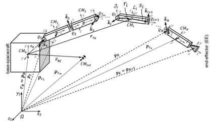
Figure 3 Schematic diagram of a space robot.40

P e = r c 0 + R 0   S 0 + i=1 n R i   L i MathType@MTEF@5@5@+= feaagKart1ev2aaatCvAUfeBSjuyZL2yd9gzLbvyNv2CaerbuLwBLn hiov2DGi1BTfMBaeXatLxBI9gBaerbd9wDYLwzYbItLDharqqtubsr 4rNCHbGeaGqkY=Mj0xXdbba91rFfpec8Eeeu0xXdbba9frFj0=OqFf ea0dXdd9vqaq=JfrVkFHe9pgea0dXdar=Jb9hs0dXdbPYxe9vr0=vr 0=vqpWqaaeaabiGaciaacaqabeaadaqaaqaaaOqaaGqadKqzGeaeaa aaaaaaa8qacaWFqbGcpaWaaSbaaSqaaKqzadWdbiaa=vgaaSWdaeqa aKqzGeWdbiabg2da9iaa=jhal8aadaWgaaqaaKqzadWdbiaa=ngal8 aadaWgaaadbaqcLbmapeGaiWiGicdaaWWdaeqaaaWcbeaajugib8qa cqGHRaWkcaWHsbGcpaWaaSbaaSqaaKqzadWdbiaaicdaaSWdaeqaaK qzGeWdbiaacckacaWFtbGcpaWaaSbaaSqaaKqzadWdbiaaicdaaSWd aeqaaKqzGeWdbiabgUcaROWaaybCaeqal8aabaqcLbsapeGaiaiJhM gacWaGmAypa0JaiaiJigdaaSWdaeaajugib8qacGaGmEOBaaqdpaqa aKqzGeWdbiabggHiLdaacaWHsbWcpaWaaSbaaeaajugWa8qacaWHPb aal8aabeaajugib8qacaWFGcGaa8htaSWdamaaBaaabaqcLbmapeGa a8xAaaWcpaqabaaaaa@637A@ (6.10)

where,

R i = i=0 n R i 0 MathType@MTEF@5@5@+= feaagKart1ev2aaatCvAUfeBSjuyZL2yd9gzLbvyNv2CaerbuLwBLn hiov2DGi1BTfMBaeXatLxBI9gBaerbd9wDYLwzYbItLDharqqtubsr 4rNCHbGeaGqkY=Mj0xXdbba91rFfpec8Eeeu0xXdbba9frFj0=OqFf ea0dXdd9vqaq=JfrVkFHe9pgea0dXdar=Jb9hs0dXdbPYxe9vr0=vr 0=vqpWqaaeaabiGaciaacaqabeaadaqaaqaaaOqaaKqzGeaeaaaaaa aaa8qacaWHsbWcpaWaaSbaaeaajugWa8qacaWHPbaal8aabeaajugi b8qacqGH9aqpkmaawahabeWcpaqaaKqzGeWdbiacaI5HPbGamaiMg2 da9iacaIjIWaaal8aabaqcLbsapeGaiaiYh6gaa0Wdaeaajugib8qa cqGHpis1aaGaaCOuaSWdamaaDaaabaqcLbmapeGaaCyAaaWcpaqaaK qzadWdbiaaicdaaaaaaa@4ECB@ (6.11)

P e MathType@MTEF@5@5@+= feaagKart1ev2aaatCvAUfeBSjuyZL2yd9gzLbvyNv2CaerbuLwBLn hiov2DGi1BTfMBaeXatLxBI9gBaerbd9wDYLwzYbItLDharqqtubsr 4rNCHbGeaGqkY=Mj0xXdbba91rFfpec8Eeeu0xXdbba9frFj0=OqFf ea0dXdd9vqaq=JfrVkFHe9pgea0dXdar=Jb9hs0dXdbPYxe9vr0=vr 0=vqpWqaaeaabiGaciaacaqabeaadaqaaqaaaOqaaGqadKqzGeaeaa aaaaaaa8qacaWFqbGcpaWaaSbaaSqaaKqzadWdbiaa=vgaaSWdaeqa aaaa@3B1D@ is the position vector of the end-effector, R 0 MathType@MTEF@5@5@+= feaagKart1ev2aaatCvAUfeBSjuyZL2yd9gzLbvyNv2CaerbuLwBLn hiov2DGi1BTfMBaeXatLxBI9gBaerbd9wDYLwzYbItLDharqqtubsr 4rNCHbGeaGqkY=Mj0xXdbba91rFfpec8Eeeu0xXdbba9frFj0=OqFf ea0dXdd9vqaq=JfrVkFHe9pgea0dXdar=Jb9hs0dXdbPYxe9vr0=vr 0=vqpWqaaeaabiGaciaacaqabeaadaqaaqaaaOqaaKqzGeaeaaaaaa aaa8qacaWHsbGcpaWaaSbaaSqaaKqzadWdbiaaicdaaSWdaeqaaaaa @3AEF@ is the rotation matrix of the base spacecraft with respect to the inertial frame, L i MathType@MTEF@5@5@+= feaagKart1ev2aaatCvAUfeBSjuyZL2yd9gzLbvyNv2CaerbuLwBLn hiov2DGi1BTfMBaeXatLxBI9gBaerbd9wDYLwzYbItLDharqqtubsr 4rNCHbGeaGqkY=Mj0xXdbba91rFfpec8Eeeu0xXdbba9frFj0=OqFf ea0dXdd9vqaq=JfrVkFHe9pgea0dXdar=Jb9hs0dXdbPYxe9vr0=vr 0=vqpWqaaeaabiGaciaacaqabeaadaqaaqaaaOqaaGqadKqzGeaeaa aaaaaaa8qacaWFmbWcpaWaaSbaaeaajugWa8qacaWFPbaal8aabeaa aaa@3B13@ is the vector from the ith joint to the (i+1)th joint, r i MathType@MTEF@5@5@+= feaagKart1ev2aaatCvAUfeBSjuyZL2yd9gzLbvyNv2CaerbuLwBLn hiov2DGi1BTfMBaeXatLxBI9gBaerbd9wDYLwzYbItLDharqqtubsr 4rNCHbGeaGqkY=Mj0xXdbba91rFfpec8Eeeu0xXdbba9frFj0=OqFf ea0dXdd9vqaq=JfrVkFHe9pgea0dXdar=Jb9hs0dXdbPYxe9vr0=vr 0=vqpWqaaeaabiGaciaacaqabeaadaqaaqaaaOqaaGqadKqzGeaeaa aaaaaaa8qacaWFYbGcpaWaaSbaaSqaaKqzadWdbiaa=LgaaSWdaeqa aaaa@3B43@ is the distance from COM of ith link to the preceding joint in the inertial frame and S i MathType@MTEF@5@5@+= feaagKart1ev2aaatCvAUfeBSjuyZL2yd9gzLbvyNv2CaerbuLwBLn hiov2DGi1BTfMBaeXatLxBI9gBaerbd9wDYLwzYbItLDharqqtubsr 4rNCHbGeaGqkY=Mj0xXdbba91rFfpec8Eeeu0xXdbba9frFj0=OqFf ea0dXdd9vqaq=JfrVkFHe9pgea0dXdar=Jb9hs0dXdbPYxe9vr0=vr 0=vqpWqaaeaabiGaciaacaqabeaadaqaaqaaaOqaaGqadKqzGeaeaa aaaaaaa8qacaWFtbWcpaWaaSbaaeaajugWa8qacaWGPbaal8aabeaa aaa@3B1E@ is distance from COM of ith link to the subsequently joint in the inertial frame. The translational and rotational Jacobian for the COM of the ith link can be expressed as follows:

J v m i = j=1 i [ k=1 j R j θ k r j + k=1 j1 R j1 θ k S j1 ],      J ω m i = j=1 i R j1 0   k ̂     MathType@MTEF@5@5@+= feaagKart1ev2aaatCvAUfeBSjuyZL2yd9gzLbvyNv2CaerbuLwBLn hiov2DGi1BTfMBaeXatLxBI9gBaerbd9wDYLwzYbItLDharqqtubsr 4rNCHbGeaGqkY=Mj0xXdbba91rFfpec8Eeeu0xXdbba9frFj0=OqFf ea0dXdd9vqaq=JfrVkFHe9pgea0dXdar=Jb9hs0dXdbPYxe9vr0=vr 0=vqpWqaaeaabiGaciaacaqabeaadaqaaqaaaOqaaabaaaaaaaaape GaaCOsa8aadaWgaaWcbaWdbiaahAhapaWaaSbaaWqaa8qacaWHTbWd amaaBaaabaWdbiaahMgaa8aabeaaaeqaaaWcbeaak8qacqGH9aqpda GfWbqabSWdaeaaieWapeGaa8NAaiabg2da9iaaigdaa8aabaWdbiaa =Lgaa0WdaeaapeGaeyyeIuoaaOWaamWaa8aabaWdbmaawahabeWcpa qaa8qacaWFRbGaeyypa0JaaGymaaWdaeaapeGaa8NAaaqdpaqaa8qa cqGHris5aaGcdaWcaaWdaeaapeGaeyOaIyRaaCOua8aadaWgaaWcba WdbiaahQgaa8aabeaaaOqaa8qacqGHciITcqaH4oqCpaWaaSbaaSqa a8qacaWGRbaapaqabaaaaOWdbiaa=jhapaWaaSbaaSqaa8qacaWFQb aapaqabaGcpeGaey4kaSYaaybCaeqal8aabaWdbiaa=TgacqGH9aqp caaIXaaapaqaa8qacaWFQbGaeyOeI0IaaGymaaqdpaqaa8qacqGHri s5aaGcdaWcaaWdaeaapeGaeyOaIyRaaCOua8aadaWgaaWcbaWdbiaa hQgacqGHsislcaaIXaaapaqabaaakeaapeGaeyOaIyRaeqiUde3dam aaBaaaleaapeGaam4AaaWdaeqaaaaak8qacaWFtbWdamaaBaaaleaa peGaa8NAaiabgkHiTiaaigdaa8aabeaaaOWdbiaawUfacaGLDbaaca GGSaGaa8hOaiaa=bkacaWFGcGaa8hOaiaacckacaWHkbWdamaaBaaa leaapeGaeqyYdC3damaaBaaameaapeGaaCyBa8aadaWgaaqaa8qaca WHPbaapaqabaaabeaaaSqabaGcpeGaeyypa0ZaaybCaeqal8aabaWd biaa=PgacqGH9aqpcaaIXaaapaqaa8qacaWFPbaan8aabaWdbiabgg HiLdaakiaahkfapaWaa0baaSqaa8qacaWHQbGaeyOeI0IaaGymaaWd aeaapeGaaGimaaaakiaa=bkapaWaaCbiaeaapeGaa83AaaWcpaqabe aapeGaeSOadqcaaOGaa8hOaiaacckacaGGGcaaaa@8B9A@ (6.12)

Accordingly, C m MathType@MTEF@5@5@+= feaagKart1ev2aaatCvAUfeBSjuyZL2yd9gzLbvyNv2CaerbuLwBLn hiov2DGi1BTfMBaeXatLxBI9gBaerbd9wDYLwzYbItLDharqqtubsr 4rNCHbGeaGqkY=Mj0xXdbba91rFfpec8Eeeu0xXdbba9frFj0=OqFf ea0dXdd9vqaq=JfrVkFHe9pgea0dXdar=Jb9hs0dXdbPYxe9vr0=vr 0=vqpWqaaeaabiGaciaacaqabeaadaqaaqaaaOqaaKqzGeaeaaaaaa aaa8qacaWHdbGcpaWaaSbaaSqaaKqzadWdbiaah2gaaSWdaeqaaaaa @3B1C@ the matrix can be found as,

C m ( θ, θ ˙ )=[ c 11 c 12 c 1n c 21 c 22 c 2n ... c n1 c n2 . c nn ],          c kj = i=1 n c ijk   θ ˙ i = 1 2 i=1 n [ d kj θ i + d ki θ j d ij θ k ]  θ ˙ i MathType@MTEF@5@5@+= feaagKart1ev2aqatCvAUfeBSjuyZL2yd9gzLbvyNv2CaerbuLwBLn hiov2DGi1BTfMBaeXatLxBI9gBaerbd9wDYLwzYbItLDharqqtubsr 4rNCHbGeaGqkY=Mj0xXdbba91rFfpec8Eeeu0xXdbba9frFj0=OqFf ea0dXdd9vqaq=JfrVkFHe9pgea0dXdar=Jb9hs0dXdbPYxe9vr0=vr 0=vqpWqaaeaabiGaciaacaqabeaadaqaaqaaaOqaaabaaaaaaaaape GaaC4qa8aadaWgaaWcbaWdbiaah2gaa8aabeaak8qadaqadaWdaeaa peGaeqiUdeNaaiilaiqbeI7aX9aagaGaaaWdbiaawIcacaGLPaaacq GH9aqpdaWadaWdaeaafaqabeWadaaabaWdbiaabogapaWaaSbaaSqa a8qacaaIXaGaaGymaaWdaeqaaaGcbaWdbiaabogapaWaaSbaaSqaa8 qacaaIXaGaaGOmaaWdaeqaaaGcbaqbaeqabeGaaaqaa8qacqGHMacV a8aabaWdbiaabogapaWaaSbaaSqaa8qacaaIXaGaaeOBaaWdaeqaaa aaaOqaa8qacaqGJbWdamaaBaaaleaapeGaaGOmaiaaigdaa8aabeaa aOqaa8qacaqGJbWdamaaBaaaleaapeGaaGOmaiaaikdaa8aabeaaaO qaauaabeqabiaaaeaapeGaeyOjGWlapaqaa8qacaqGJbWdamaaBaaa leaapeGaaGOmaiaab6gaa8aabeaaaaaakeaafaqabeGabaaabaWdbi aac6cacaGGUaGaaiOlaaWdaeaapeGaae4ya8aadaWgaaWcbaWdbiaa b6gacaaIXaaapaqabaaaaaGcbaqbaeqabiqaaaqaa8qacqGHMacVa8 aabaWdbiaabogapaWaaSbaaSqaa8qacaqGUbGaaGOmaaWdaeqaaaaa aOqaauaabeqabiaaaeaafaqabeGabaaabaWdbiabgAci8cWdaeaape GaeyOjGWRaaiOlaaaaa8aabaqbaeqabiqaaaqaa8qacqGHMacVa8aa baWdbiaabogapaWaaSbaaSqaa8qacaqGUbGaaeOBaaWdaeqaaaaaaa aaaaGcpeGaay5waiaaw2faaiaacYcacaGGGcGaaiiOaiaacckacaGG GcGaaiiOaiaacckacaGGGcGaaiiOaiaacckacaWGJbWdamaaBaaale aapeGaam4AaiaadQgaa8aabeaak8qacqGH9aqpdaGfWbqabSWdaeaa peGaamyAaiabg2da9iaaigdaa8aabaWdbiaad6gaa0WdaeaapeGaey yeIuoaaOGaam4ya8aadaWgaaWcbaWdbiaadMgacaWGQbGaam4AaaWd aeqaaOWdbiaacckacuaH4oqCpaGbaiaadaWgaaWcbaWdbiaadMgaa8 aabeaak8qacqGH9aqpdaWcaaWdaeaapeGaaGymaaWdaeaapeGaaGOm aaaadaGfWbqabSWdaeaapeGaamyAaiabg2da9iaaigdaa8aabaWdbi aad6gaa0WdaeaapeGaeyyeIuoaaOWaamWaa8aabaWdbmaalaaapaqa a8qacqGHciITcaWGKbWdamaaBaaaleaapeGaam4AaiaadQgaa8aabe aaaOqaa8qacqGHciITcqaH4oqCpaWaaSbaaSqaa8qacaWGPbaapaqa baaaaOWdbiabgUcaRmaalaaapaqaa8qacqGHciITcaWGKbWdamaaBa aaleaapeGaam4AaiaadMgaa8aabeaaaOqaa8qacqGHciITcqaH4oqC paWaaSbaaSqaa8qacaWGQbaapaqabaaaaOWdbiabgkHiTmaalaaapa qaa8qacqGHciITcaWGKbWdamaaBaaaleaapeGaamyAaiaadQgaa8aa beaaaOqaa8qacqGHciITcqaH4oqCpaWaaSbaaSqaa8qacaWGRbaapa qabaaaaaGcpeGaay5waiaaw2faaiaacckacuaH4oqCpaGbaiaadaWg aaWcbaWdbiaadMgaa8aabeaaaaa@B575@ (6.13)

Dynamic coupling between manipulator and base-spacecraft

The dynamic coupling is referred to the relative forces and moments generated from the motion of the manipulator and applied on the base spacecraft, which causes the attitude to change. Modelling the dynamic coupling is based on the conservation of relative linear and angular momentum of the manipulator. In order to find the dynamic coupling matrices, D sc.m MathType@MTEF@5@5@+= feaagKart1ev2aaatCvAUfeBSjuyZL2yd9gzLbvyNv2CaerbuLwBLn hiov2DGi1BTfMBaeXatLxBI9gBaerbd9wDYLwzYbItLDharqqtubsr 4rNCHbGeaGqkY=Mj0xXdbba91rFfpec8Eeeu0xXdbba9frFj0=OqFf ea0dXdd9vqaq=JfrVkFHe9pgea0dXdar=Jb9hs0dXdbPYxe9vr0=vr 0=vqpWqaaeaabiGaciaacaqabeaadaqaaqaaaOqaaKqzGeaeaaaaaa aaa8qacaWHebWcpaWaaSbaaeaajugWa8qacaWHZbGaaC4yaiacycOG UaGaialGh2gaaSWdaeqaaaaa@4005@ and C sc.m MathType@MTEF@5@5@+= feaagKart1ev2aaatCvAUfeBSjuyZL2yd9gzLbvyNv2CaerbuLwBLn hiov2DGi1BTfMBaeXatLxBI9gBaerbd9wDYLwzYbItLDharqqtubsr 4rNCHbGeaGqkY=Mj0xXdbba91rFfpec8Eeeu0xXdbba9frFj0=OqFf ea0dXdd9vqaq=JfrVkFHe9pgea0dXdar=Jb9hs0dXdbPYxe9vr0=vr 0=vqpWqaaeaabiGaciaacaqabeaadaqaaqaaaOqaaKqzGeaeaaaaaa aaa8qacaWHdbWcpaWaaSbaaeaajugWa8qacaWHZbGaaC4yaiacycOG UaGaialGh2gaaSWdaeqaaaaa@4004@ , one has to compute the embedded matrices D vm MathType@MTEF@5@5@+= feaagKart1ev2aaatCvAUfeBSjuyZL2yd9gzLbvyNv2CaerbuLwBLn hiov2DGi1BTfMBaeXatLxBI9gBaerbd9wDYLwzYbItLDharqqtubsr 4rNCHbGeaGqkY=Mj0xXdbba91rFfpec8Eeeu0xXdbba9frFj0=OqFf ea0dXdd9vqaq=JfrVkFHe9pgea0dXdar=Jb9hs0dXdbPYxe9vr0=vr 0=vqpWqaaeaabiGaciaacaqabeaadaqaaqaaaOqaaKqzGeaeaaaaaa aaa8qacaWHebGcpaWaaSbaaSqaaKqzadWdbiaahAhacaWHTbaal8aa beaaaaa@3C1C@ , D ωm MathType@MTEF@5@5@+= feaagKart1ev2aaatCvAUfeBSjuyZL2yd9gzLbvyNv2CaerbuLwBLn hiov2DGi1BTfMBaeXatLxBI9gBaerbd9wDYLwzYbItLDharqqtubsr 4rNCHbGeaGqkY=Mj0xXdbba91rFfpec8Eeeu0xXdbba9frFj0=OqFf ea0dXdd9vqaq=JfrVkFHe9pgea0dXdar=Jb9hs0dXdbPYxe9vr0=vr 0=vqpWqaaeaabiGaciaacaqabeaadaqaaqaaaOqaaGqababaaaaaaa aapeGaa8hramaaBaaaleaacqaHjpWDcaWFTbaabeaaaaa@3AE4@ , C vm MathType@MTEF@5@5@+= feaagKart1ev2aaatCvAUfeBSjuyZL2yd9gzLbvyNv2CaerbuLwBLn hiov2DGi1BTfMBaeXatLxBI9gBaerbd9wDYLwzYbItLDharqqtubsr 4rNCHbGeaGqkY=Mj0xXdbba91rFfpec8Eeeu0xXdbba9frFj0=OqFf ea0dXdd9vqaq=JfrVkFHe9pgea0dXdar=Jb9hs0dXdbPYxe9vr0=vr 0=vqpWqaaeaabiGaciaacaqabeaadaqaaqaaaOqaaKqzGeaeaaaaaa aaa8qacaWHdbGcpaWaaSbaaSqaaKqzadWdbiaahAhacaWHTbaal8aa beaaaaa@3C1B@ and C ωm MathType@MTEF@5@5@+= feaagKart1ev2aaatCvAUfeBSjuyZL2yd9gzLbvyNv2CaerbuLwBLn hiov2DGi1BTfMBaeXatLxBI9gBaerbd9wDYLwzYbItLDharqqtubsr 4rNCHbGeaGqkY=Mj0xXdbba91rFfpec8Eeeu0xXdbba9frFj0=OqFf ea0dXdd9vqaq=JfrVkFHe9pgea0dXdar=Jb9hs0dXdbPYxe9vr0=vr 0=vqpWqaaeaabiGaciaacaqabeaadaqaaqaaaOqaaGqababaaaaaaa aapeGaa83qamaaBaaaleaacqaHjpWDcaWFTbaabeaaaaa@3AE3@ from relative linear and angular momentum where:

D sc.m =[ D vm D ωm ] MathType@MTEF@5@5@+= feaagKart1ev2aqatCvAUfeBSjuyZL2yd9gzLbvyNv2CaerbuLwBLn hiov2DGi1BTfMBaeXatLxBI9gBaerbd9wDYLwzYbItLDharqqtubsr 4rNCHbGeaGqkY=Mj0xXdbba91rFfpec8Eeeu0xXdbba9frFj0=OqFf ea0dXdd9vqaq=JfrVkFHe9pgea0dXdar=Jb9hs0dXdbPYxe9vr0=vr 0=vqpWqaaeaabiGaciaacaqabeaadaqaaqaaaOqaaabaaaaaaaaape GaaCira8aadaWgaaWcbaWdbiaahohacaWHJbGaaiOlaiaah2gaa8aa beaak8qacqGH9aqpdaWadaWdaeaafaqabeGabaaabaWdbiaahseapa WaaSbaaSqaa8qacaWH2bGaaCyBaaWdaeqaaaGcbaWdbiaahseapaWa aSbaaSqaa8qacqaHjpWDcaWHTbaapaqabaaaaaGcpeGaay5waiaaw2 faaaaa@465E@ and C sc.m =[ C vm C ωm ] MathType@MTEF@5@5@+= feaagKart1ev2aqatCvAUfeBSjuyZL2yd9gzLbvyNv2CaerbuLwBLn hiov2DGi1BTfMBaeXatLxBI9gBaerbd9wDYLwzYbItLDharqqtubsr 4rNCHbGeaGqkY=Mj0xXdbba91rFfpec8Eeeu0xXdbba9frFj0=OqFf ea0dXdd9vqaq=JfrVkFHe9pgea0dXdar=Jb9hs0dXdbPYxe9vr0=vr 0=vqpWqaaeaabiGaciaacaqabeaadaqaaqaaaOqaaabaaaaaaaaape GaaC4qa8aadaWgaaWcbaWdbiaahohacaWHJbGaaiOlaiaah2gaa8aa beaak8qacqGH9aqpdaWadaWdaeaafaqabeGabaaabaWdbiaahoeapa WaaSbaaSqaa8qacaWH2bGaaCyBaaWdaeqaaaGcbaWdbiaahoeapaWa aSbaaSqaa8qacaWHjpGaaCyBaaWdaeqaaaaaaOWdbiaawUfacaGLDb aaaaa@45E3@ (6.14)

Based on the conservation of relative linear momentum, it can be found that:

D vm = i=1 n m i   J T i ,        C vm = i=1 n m i J ˙ T i MathType@MTEF@5@5@+= feaagKart1ev2aqatCvAUfeBSjuyZL2yd9gzLbvyNv2CaerbuLwBLn hiov2DGi1BTfMBaeXatLxBI9gBaerbd9wDYLwzYbItLDharqqtubsr 4rNCHbGeaGqkY=Mj0xXdbba91rFfpec8Eeeu0xXdbba9frFj0=OqFf ea0dXdd9vqaq=JfrVkFHe9pgea0dXdar=Jb9hs0dXdbPYxe9vr0=vr 0=vqpWqaaeaabiGaciaacaqabeaadaqaaqaaaOqaaabaaaaaaaaape GaaCira8aadaWgaaWcbaWdbiaahAhacaWHTbaapaqabaGcpeGaeyyp a0ZaaybCaeqal8aabaacbmWdbiaa=LgacqGH9aqpcaaIXaaapaqaa8 qacaWFUbaan8aabaWdbiabggHiLdaakiaad2gapaWaaSbaaSqaa8qa caWGPbaapaqabaGcpeGaa8hOaiaahQeapaWaaSbaaSqaa8qacaWHub WdamaaBaaameaapeGaaCyAaaWdaeqaaaWcbeaak8qacaGGSaGaa8hO aiaa=bkacaWFGcGaa8hOaiaacckacaGGGcGaaiiOaiaahoeapaWaaS baaSqaa8qacaWH2bGaaCyBaaWdaeqaaOWdbiabg2da9maawahabeWc paqaa8qacaWFPbGaeyypa0JaaGymaaWdaeaapeGaa8NBaaqdpaqaa8 qacqGHris5aaGccaWGTbWdamaaBaaaleaapeGaamyAaaWdaeqaaOWd biqahQeapaGbaiaadaWgaaWcbaWdbiaahsfapaWaaSbaaWqaa8qaca WHPbaapaqabaaaleqaaaaa@617A@ (6.15)

where J T i MathType@MTEF@5@5@+= feaagKart1ev2aaatCvAUfeBSjuyZL2yd9gzLbvyNv2CaerbuLwBLn hiov2DGi1BTfMBaeXatLxBI9gBaerbd9wDYLwzYbItLDharqqtubsr 4rNCHbGeaGqkY=Mj0xXdbba91rFfpec8Eeeu0xXdbba9frFj0=OqFf ea0dXdd9vqaq=JfrVkFHe9pgea0dXdar=Jb9hs0dXdbPYxe9vr0=vr 0=vqpWqaaeaabiGaciaacaqabeaadaqaaqaaaOqaaKqzGeaeaaaaaa aaa8qacaWHkbWcpaWaaSbaaeaadaWgaaadbaqcLbmapeGaiGguhsfa l8aadaWgaaadbaqcLbmapeGaaCyAaaadpaqabaaabeaaaSqabaaaaa@3E70@ is the relative linear translational Jacobian and can be expressed as:

J T i = j=1 i [ k=1 j R j θ k   r j + k=1 j1 R j1 θ k s j1 ] MathType@MTEF@5@5@+= feaagKart1ev2aaatCvAUfeBSjuyZL2yd9gzLbvyNv2CaerbuLwBLn hiov2DGi1BTfMBaeXatLxBI9gBaerbd9wDYLwzYbItLDharqqtubsr 4rNCHbGeaGqkY=Mj0xXdbba91rFfpec8Eeeu0xXdbba9frFj0=OqFf ea0dXdd9vqaq=JfrVkFHe9pgea0dXdar=Jb9hs0dXdbPYxe9vr0=vr 0=vqpWqaaeaabiGaciaacaqabeaadaqaaqaaaOqaaKqzGeaeaaaaaa aaa8qacaWHkbWcpaWaaSbaaeaajugWa8qacaWHubWcpaWaiWiGBaaa meacmcycLbmapeGaiqkGhMgaaWWdaeqcmciaaSqabaqcLbsapeGaey ypa0JcdaGfWbqabSWdaeaaieWajugib8qacGaGK+NAaiadasQH9aqp cGaGKIymaaWcpaqaaKqzGeWdbiacaY1FPbaan8aabaqcLbsapeGaey yeIuoaaOWaamWaa8aabaWdbmaawahabeWcpaqaaKqzGeWdbiacaY7F RbGamaiVg2da9iacaYlIXaaal8aabaqcLbsapeGaiaiA=Pgaa0Wdae aajugib8qacWaGmAyeIuoaaOWaaSaaa8aabaqcLbsapeGaeyOaIyRa aCOuaSWdamaaBaaabaqcLbmapeGaaCOAaaWcpaqabaaakeaajugib8 qacqGHciITcqaH4oqCl8aadaWgaaqaaKqzadWdbiaadUgaaSWdaeqa aaaajugib8qacaWFGcGaa8NCaSWdamaaBaaabaqcLbmapeGaa8NAaa WcpaqabaqcLbsapeGaey4kaSIcdaGfWbqabSWdaeaajugib8qacGaG 8+3AaiadaYRH9aqpcGaG8IymaaWcpaqaaKqzGeWdbiacaI2FQbGama iAgkHiTiacaIgIXaaan8aabaqcLbsapeGamaiJggHiLdaakmaalaaa paqaaKqzGeWdbiabgkGi2kacyc4HsbWcpaWaiGjGBaaabGaMaMqzad Wdbiacyc4HQbGamGjGgkHiTiacyciIXaaal8aabKaMacaakeaajugi b8qacqGHciITcqaH4oqCl8aadaWgaaqaaKqzadWdbiaadUgaaSWdae qaaaaajugib8qacaWFZbGcpaWaaSbaaSqaaKqzadWdbiaa=PgacqGH sislcaaIXaaal8aabeaaaOWdbiaawUfacaGLDbaaaaa@9F03@ (6.16)

Based on the conservation of relative angular momentum, it can be found that:

D ωm = i=1 n ( R i 0 I i R i 0 T J ω i + m i [ p c i ] × J T i ) , C ωm = i=1 n ( R i 0 I i R i 0 T J ˙ ω i + m i [ p c i ] × J ˙ T i ) MathType@MTEF@5@5@+= feaagKart1ev2aaatCvAUfeBSjuyZL2yd9gzLbvyNv2CaerbuLwBLn hiov2DGi1BTfMBaeXatLxBI9gBaerbd9wDYLwzYbItLDharqqtubsr 4rNCHbGeaGqkY=Mj0xXdbba91rFfpec8Eeeu0xXdbba9frFj0=OqFf ea0dXdd9vqaq=JfrVkFHe9pgea0dXdar=Jb9hs0dXdbPYxe9vr0=vr 0=vqpWqaaeaabiGaciaacaqabeaadaqaaqaaaOqaaGqababaaaaaaa aapeGaa8hramaaBaaaleaaiiaacqGFjpWDcaWFTbaabeaakiaa=1da daaeWbqaamaabmaabaGaa8NuamaaDaaaleaacaWFPbaabaGaa8hmaa aakiaa=LeadaWgaaWcbaGaa8xAaaqabaGccaWFsbWaa0baaSqaaiaa =LgaaeaacaWFWaWaaWbaaWqabeaacaWFubaaaaaakiaa=PeajugWai ab+L8a3PWaaSbaaSqaaiaa=LgaaeqaaOGaa83kaGqaaiaa91gadaWg aaWcbaGaa0xAaaqabaGcpaWaamWaaeaaieWacaaFWbWaaSbaaSqaai aa8ngadaWgaaadbaGaaWxAaaqabaaaleqaaaGccaGLBbGaayzxaaWa aSbaaSqaaiabgEna0cqabaGccaWFkbWaaSbaaSqaaiaa=rfadaWgaa adbaGaa8xAaaqabaaaleqaaaGcpeGaayjkaiaawMcaaaWcbaGaa8xA aiaa=1dacaWFXaaabaGaa8NBaaqdcqGHris5aOGaaiilaiaa=neada WgaaWcbaGae4xYdCNaa8xBaaqabaGccqGH9aqpdaGfWbqabSWdaeaa peGaaWxAaiabg2da9iaaigdaa8aabaWdbiaa85gaa0WdaeaapeGaey yeIuoaaOWaaeWaaeaacaWFsbWaa0baaSqaaiaa=LgaaeaacaWFWaaa aOGaaCysa8aadaWgaaWcbaWdbiaahMgaa8aabeaak8qacaWHsbWdam aaDaaaleaapeGaaCyAaaWdaeaapeGaaGimamaaCaaameqabaGaaCiv aaaaaaGcceWFkbGbaiaajugWaiab+L8a3PWaaSbaaSqaaiaa=Lgaae qaaOWdaiabgUcaRiaa91gadaWgaaWcbaGaa0xAaaqabaGcdaWadaqa aiaa8bhadaWgaaWcbaGaaW3yamaaBaaameaacaaFPbaabeaaaSqaba aakiaawUfacaGLDbaadaWgaaWcbaGaey41aqlabeaakiqa=PeagaGa amaaBaaaleaacaWFubWaaSbaaWqaaiaa=LgaaeqaaaWcbeaaaOWdbi aawIcacaGLPaaaaaa@85AD@ (6.17)

where p c i MathType@MTEF@5@5@+= feaagKart1ev2aaatCvAUfeBSjuyZL2yd9gzLbvyNv2CaerbuLwBLn hiov2DGi1BTfMBaeXatLxBI9gBaerbd9wDYLwzYbItLDharqqtubsr 4rNCHbGeaGqkY=Mj0xXdbba91rFfpec8Eeeu0xXdbba9frFj0=OqFf ea0dXdd9vqaq=JfrVkFHe9pgea0dXdar=Jb9hs0dXdbPYxe9vr0=vr 0=vqpWqaaeaabiGaciaacaqabeaadaqaaqaaaOqaaGqadKqzGeGaa8 hCaOWaaSbaaSqaaKqzadGaa83yaSWaaSbaaWqaaKqzadGaa8xAaaad beaaaSqabaaaaa@3D49@ is the position vector of CM of ith link with respect to inertia frame and J ω i MathType@MTEF@5@5@+= feaagKart1ev2aaatCvAUfeBSjuyZL2yd9gzLbvyNv2CaerbuLwBLn hiov2DGi1BTfMBaeXatLxBI9gBaerbd9wDYLwzYbItLDharqqtubsr 4rNCHbGeaGqkY=Mj0xXdbba91rFfpec8Eeeu0xXdbba9frFj0=OqFf ea0dXdd9vqaq=JfrVkFHe9pgea0dXdar=Jb9hs0dXdbPYxe9vr0=vr 0=vqpWqaaeaabiGaciaacaqabeaadaqaaqaaaOqaaGqabiaa=Peada WgaaWcbaGaeqyYdChabeaakmaaBaaaleaadaWgaaadbaGaa8xAaaqa baaaleqaaaaa@3B34@ is the angular velocity Jacobian of the ith link. Therefore, the final inertial acceleration matrix D and the centrifugal and Coriolis acceleration matrix C are:

D=[ D v D vω D vm D vω T D ω D ωm D vm T D ωm T   D m ],                 C=[ 0 C sc.v C vm 0 C sc.ω C ωm C vm T C ωm T C m ] MathType@MTEF@5@5@+= feaagKart1ev2aqatCvAUfeBSjuyZL2yd9gzLbvyNv2CaerbuLwBLn hiov2DGi1BTfMBaeXatLxBI9gBaerbd9wDYLwzYbItLDharqqtubsr 4rNCHbGeaGqkY=Mj0xXdbba91rFfpec8Eeeu0xXdbba9frFj0=OqFf ea0dXdd9vqaq=JfrVkFHe9pgea0dXdar=Jb9hs0dXdbPYxe9vr0=vr 0=vqpWqaaeaabiGaciaacaqabeaadaqaaqaaaOqaaabaaaaaaaaape GaaCiraiabg2da9maadmaapaqaauaabeqadmaaaeaapeGaaCira8aa daWgaaWcbaWdbiaahAhaa8aabeaaaOqaa8qacaWHebWdamaaBaaale aapeGaaCODaiabeM8a3bWdaeqaaaGcbaWdbiaahseapaWaaSbaaSqa a8qacaWH2bGaaCyBaaWdaeqaaaGcbaWdbiaahseapaWaa0baaSqaa8 qacaWH2bGaeqyYdChapaqaa8qacaWHubaaaaGcpaqaa8qacaWHebWd amaaBaaaleaapeGaeqyYdChapaqabaaakeaapeGaaCira8aadaWgaa WcbaWdbiabeM8a3jaah2gaa8aabeaaaOqaa8qacaWHebWdamaaDaaa leaapeGaaCODaiaah2gaa8aabaWdbiaahsfaaaaak8aabaWdbiaahs eapaWaa0baaSqaa8qacqaHjpWDcaWHTbaapaqaa8qacaWHubaaaOGa aiiOaaWdaeaapeGaaCira8aadaWgaaWcbaWdbiaah2gaa8aabeaaaa aak8qacaGLBbGaayzxaaGaaiilaGqadiaa=bkacaWFGcGaa8hOaiaa =bkacaWFGcGaa8hOaiaa=bkacaWFGcGaa8hOaiaa=bkacaWFGcGaa8 hOaiaa=bkacaWFGcGaa8hOaiaa=bkacaWFGcGaaC4qaiabg2da9maa dmaapaqaauaabeqadmaaaeaapeGaaGimaaWdaeaapeGaaC4qa8aada WgaaWcbaWdbiaahohacaWHJbGaaiOlaiaahAhaa8aabeaaaOqaa8qa caWHdbWdamaaBaaaleaapeGaaCODaiaah2gaa8aabeaaaOqaa8qaca aIWaaapaqaa8qacaWHdbWdamaaBaaaleaapeGaaC4CaiaahogacaGG UaGaeqyYdChapaqabaaakeaapeGaaC4qa8aadaWgaaWcbaWdbiabeM 8a3jaah2gaa8aabeaaaOqaa8qacaWHdbWdamaaDaaaleaapeGaaCOD aiaah2gaa8aabaWdbiaahsfaaaaak8aabaWdbiaahoeapaWaa0baaS qaa8qacqaHjpWDcaWHTbaapaqaa8qacaWHubaaaaGcpaqaa8qacaWH dbWdamaaBaaaleaapeGaaCyBaaWdaeqaaaaaaOWdbiaawUfacaGLDb aaaaa@9411@ (6.18)

Forward and inverse kinematics for a space robot

By referring to equation (6.12) and Figure 3, the forward kinematics for the end-effector of the manipulator can be expressed as:

P ˙ e =[ J v sc J v m ][ X ˙ θ ˙ ] MathType@MTEF@5@5@+= feaagKart1ev2aqatCvAUfeBSjuyZL2yd9gzLbvyNv2CaerbuLwBLn hiov2DGi1BTfMBaeXatLxBI9gBaerbd9wDYLwzYbItLDharqqtubsr 4rNCHbGeaGqkY=Mj0xXdbba91rFfpec8Eeeu0xXdbba9frFj0=OqFf ea0dXdd9vqaq=JfrVkFHe9pgea0dXdar=Jb9hs0dXdbPYxe9vr0=vr 0=vqpWqaaeaabiGaciaacaqabeaadaqaaqaaaOqaaGqadabaaaaaaa aapeGab8hua8aagaGaamaaBaaaleaapeGaa8xzaaWdaeqaaOWdbiab g2da9maadmaapaqaauaabeqabiaaaeaapeGaaCOsa8aadaWgaaWcba WdbiaahAhaa8aabeaakmaaBaaaleaapeGaaC4Caiaahogaa8aabeaa aOqaa8qacaWHkbWdamaaBaaaleaapeGaaCODa8aadaWgaaadbaWdbi aah2gaa8aabeaaaSqabaaaaaGcpeGaay5waiaaw2faamaadmaapaqa auaabeqaceaaaeaapeGab8hwa8aagaGaaaqaa8qacuaH4oqCpaGbai aaaaaapeGaay5waiaaw2faaaaa@49A6@ (6.19)

Through using the pseudo inverse, the inverse kinematics can be expressed as:

θ ˙ = ( J v m T J v m ) 1   J v m T ( P ˙ e J v sc X ˙ ) MathType@MTEF@5@5@+= feaagKart1ev2aqatCvAUfeBSjuyZL2yd9gzLbvyNv2CaerbuLwBLn hiov2DGi1BTfMBaeXatLxBI9gBaerbd9wDYLwzYbItLDharqqtubsr 4rNCHbGeaGqkY=Mj0xXdbba91rFfpec8Eeeu0xXdbba9frFj0=OqFf ea0dXdd9vqaq=JfrVkFHe9pgea0dXdar=Jb9hs0dXdbPYxe9vr0=vr 0=vqpWqaaeaabiGaciaacaqabeaadaqaaqaaaOqaaabaaaaaaaaape GafqiUde3dayaacaWdbiabg2da9maabmaapaqaa8qacaWHkbWdamaa DaaaleaapeGaaCODa8aadaWgaaadbaWdbiaah2gaa8aabeaaaSqaa8 qacaWHubaaaOGaaCOsa8aadaWgaaWcbaWdbiaahAhapaWaaSbaaWqa a8qacaWHTbaapaqabaaaleqaaaGcpeGaayjkaiaawMcaa8aadaahaa Wcbeqaa8qacqGHsislcaaIXaaaaOGaaiiOaiaahQeapaWaa0baaSqa a8qacaWH2bWdamaaBaaameaapeGaaCyBaaWdaeqaaaWcbaWdbiaahs faaaGcdaqadaWdaeaaieWapeGab8hua8aagaGaamaaBaaaleaapeGa a8xzaaWdaeqaaOWdbiabgkHiTiaahQeapaWaaSbaaSqaa8qacaWH2b WdamaaBaaameaapeGaaC4Caiaahogaa8aabeaaaSqabaGcpeGab8hw a8aagaGaaaWdbiaawIcacaGLPaaaaaa@55AD@ (6.20)

As

J v e sc =[ E J v sc ' ],     J v e sc ' = R 0 ϕ   S 0 + i=1 n R i ϕ L i , MathType@MTEF@5@5@+= feaagKart1ev2aaatCvAUfeBSjuyZL2yd9gzLbvyNv2CaerbuLwBLn hiov2DGi1BTfMBaeXatLxBI9gBaerbd9wDYLwzYbItLDharqqtubsr 4rNCHbGeaGqkY=Mj0xXdbba91rFfpec8Eeeu0xXdbba9frFj0=OqFf ea0dXdd9vqaq=JfrVkFHe9pgea0dXdar=Jb9hs0dXdbPYxe9vr0=vr 0=vqpWqaaeaabiGaciaacaqabeaadaqaaqaaaOqaaKqzGeaeaaaaaa aaa8qacaWHkbWcpaWaaSbaaeaajugWa8qacaWH2bWcpaWaaSbaaWqa aKqzadWdbiaahwgaaWWdaeqaaaWcbeaadaWgaaqaa8qadaWgaaqaam aaBaaajiaWbaqcLbmacGaAaE4CaiacOb4HJbaameqaaaWcbeaaa8aa beaajugib8qacqGH9aqpkmaadmaapaqaaKqzGeqbaeqabeGaaaGcba qcLbsapeGaaCyraaGcpaqaaKqzGeWdbiaahQeal8aadGaDOTbaaeac 0HwcLbmapeGaiqhAhAhaaSWdaeqc0HgadGaDW2baaeac0bBcLbmape GaiqhYhohacGaDiF4yaaWcpaqaiqhSieGajugWa8qacGaGaI1=ibWF NaaaaaaaaOGaay5waiaaw2faaKqzGeGaaiilaGqadiaa+bkacaGFGc Gaa4hOaiaa+bkacaGFGaGaaCOsaSWdamaaBaaabaqcLbmapeGaiGgA hAhal8aadaWgaaadbaqcLbmapeGaiWfDhwgaaWWdaeqaaaWcbeaada qhaaqaaKqzadWdbiacqb+HZbGaiaf4hogaaSWdaeaajugWa8qacGaG aYR=ibWFNaaaaKqzGeGaeyypa0JcdaWcaaWdaeaajugib8qacqGHci ITcGaSaEOuaOWdamacWc4gaaWcbGaSaMqzadWdbiacWciIWaaal8aa bKaSacaakeaajugib8qacqGHciITcqaHvpGzaaGaa4hOaiaa+nfak8 aadaWgaaWcbaqcLbmapeGaaGimaaWcpaqabaqcLbsapeGaey4kaSIc daGfWbqabSWdaeaajugib8qacGaGy6xAaiadaIPH9aqpcGaGyIymaa WcpaqaaKqzGeWdbiacasNFUbaan8aabaqcLbsapeGaeyyeIuoaaOWa aSaaa8aabaqcLbsapeGaeyOaIyRaialGhkfal8aadGaSaUbaaeacWc ycLbmapeGaialGhMgaaSWdaeqcWciaaOqaaKqzGeWdbiabgkGi2kab ew9aMbaacaGFmbGcpaWaaSbaaSqaaKqzadWdbiaa+LgaaSWdaeqaaK qzGeGaaiilaaaa@AF56@ (6.21)

J v e m = i=1 n k=1 i ( R i θ k )  L i MathType@MTEF@5@5@+= feaagKart1ev2aaatCvAUfeBSjuyZL2yd9gzLbvyNv2CaerbuLwBLn hiov2DGi1BTfMBaeXatLxBI9gBaerbd9wDYLwzYbItLDharqqtubsr 4rNCHbGeaGqkY=Mj0xXdbba91rFfpec8Eeeu0xXdbba9frFj0=OqFf ea0dXdd9vqaq=JfrVkFHe9pgea0dXdar=Jb9hs0dXdbPYxe9vr0=vr 0=vqpWqaaeaabiGaciaacaqabeaadaqaaqaaaOqaaKqzGeaeaaaaaa aaa8qacaWHkbGcpaWaaSbaaSqaaKqzadWdbiaahAhal8aadaWgaaad baqcLbmapeGaaCyzaaadpaqabaWcdaWgaaadbaqcLbmapeGaaCyBaa adpaqabaaaleqaaKqzGeWdbiabg2da9OWaiGgGwahabKaAaUWdaeac ObicbmqcLbsapeGaiGgM=LgacWaAyAypa0JaiGgMigdaaSWdaeacOb ycLbsapeGaiGgx=5gaa0WdaeacObycLbsapeGamGgGggHiLdaakmac mcOfWbqajWiGl8aabGaJaMqzGeWdbiacKI5FRbGamqkMg2da9iacKI jIXaaal8aabGaJaMqzGeWdbiacWs3FPbaan8aabGaJaMqzGeWdbiad KcOHris5aaGcdGaVagWaa8aabGaVa+qadGaVaUaaa8aabGaVaIGabK qzGeWdbiad8cOFciITcGa7aEOuaSWdamacSd4gaaqaiWoGjugWa8qa cGa7aEyAaaWcpaqajWoGaaGcbGaVaMqzGeWdbiad8cOFciITcWaVas iUde3cpaWaiWlGBaaabGaVaMqzadWdbiac8c4GRbaal8aabKaVacaa aaGcpeGaiWlGwIcacGaVaAzkaaqcLbsacGaPa+hOaiacKc4FmbWcpa WaiqkGBaaabGaPaMqzadWdbiacKc4FPbaal8aabKaPacaaaa@9983@ (6.22)

where ϕ MathType@MTEF@5@5@+= feaagKart1ev2aaatCvAUfeBSjuyZL2yd9gzLbvyNv2CaerbuLwBLn hiov2DGi1BTfMBaeXatLxBI9gBaerbd9wDYLwzYbItLDharqqtubsr 4rNCHbGeaGqkY=Mj0xXdbba91rFfpec8Eeeu0xXdbba9frFj0=OqFf ea0dXdd9vqaq=JfrVkFHe9pgea0dXdar=Jb9hs0dXdbPYxe9vr0=vr 0=vqpWqaaeaabiGaciaacaqabeaadaqaaqaaaOqaaKqzGeaeaaaaaa aaa8qacqaHvpGzaaa@3985@ is the Euler angles of the base-spacecraft, R 0 MathType@MTEF@5@5@+= feaagKart1ev2aaatCvAUfeBSjuyZL2yd9gzLbvyNv2CaerbuLwBLn hiov2DGi1BTfMBaeXatLxBI9gBaerbd9wDYLwzYbItLDharqqtubsr 4rNCHbGeaGqkY=Mj0xXdbba91rFfpec8Eeeu0xXdbba9frFj0=OqFf ea0dXdd9vqaq=JfrVkFHe9pgea0dXdar=Jb9hs0dXdbPYxe9vr0=vr 0=vqpWqaaeaabiGaciaacaqabeaadaqaaqaaaOqaaKqzGeaeaaaaaa aaa8qacaWHsbWcpaWaaSbaaeaajugWa8qacaaIWaaal8aabeaaaaa@3AE5@ is the axes transformation matrix for the base-spacecraft using Yaw, Pitch and Roll (3-2-1) rotation sequence and is given by,

R 0 =[ cosϕ cosθ     cosϕ sinθ sin ψsinϕcosψ    cosϕsinθcosψ+sinϕsinψ  sinϕ cosθ     sinϕsinθsinψ+cosϕcosψ    sinϕsinθcosψcosϕsinψ      sinθ                     cosθsinψ                                     cosθcosψ ] MathType@MTEF@5@5@+= feaagKart1ev2aaatCvAUfeBSjuyZL2yd9gzLbvyNv2CaerbuLwBLn hiov2DGi1BTfMBaeXatLxBI9gBaerbd9wDYLwzYbItLDharqqtubsr 4rNCHbGeaGqkY=Mj0xXdbba91rFfpec8Eeeu0xXdbba9frFj0=OqFf ea0dXdd9vqaq=JfrVkFHe9pgea0dXdar=Jb9hs0dXdbPYxe9vr0=vr 0=vqpWqaaeaabiGaciaacaqabeaadaqaaqaaaOqaaKqzGeaeaaaaaa aaa8qacaWHsbWcpaWaaSbaaeaajugWa8qacaaIWaaal8aabeaajugi b8qacqGH9aqpkmaadmaajugibqaabeGcbaqcLbsaciGGJbGaai4Bai aacohacqaHvpGzcaGGGcGaam4yaiaad+gacaWGZbGaeqiUdeNaaiiO aiaacckacaGGGcGaaiiOaiaacckaciGGJbGaai4BaiaacohacqaHvp GzcaGGGcGaam4CaiaadMgacaWGUbGaeqiUdeNaaiiOaiaadohacaWG PbGaamOBaiaacckacqaHipqEcqGHsislciGGZbGaaiyAaiaac6gacq aHvpGzciGGJbGaai4BaiaacohacqaHipqEcaGGGcGaaiiOaiaaccka caGGGcGaci4yaiaac+gacaGGZbGaeqy1dyMaci4CaiaacMgacaGGUb GaeqiUdeNaci4yaiaac+gacaGGZbGaeqiYdKNaey4kaSIaci4Caiaa cMgacaGGUbGaeqy1dyMaci4CaiaacMgacaGGUbGaeqiYdKNaaiiOaa GcbaqcLbsaciGGZbGaaiyAaiaac6gacqaHvpGzcaGGGcGaam4yaiaa d+gacaWGZbGaeqiUdeNaaiiOaiaacckacaGGGcGaaiiOaiaacckaci GGZbGaaiyAaiaac6gacqaHvpGzciGGZbGaaiyAaiaac6gacqaH4oqC ciGGZbGaaiyAaiaac6gacqaHipqEcqGHRaWkciGGJbGaai4Baiaaco hacqaHvpGzciGGJbGaai4BaiaacohacqaHipqEcaGGGcGaaiiOaiaa cckacaGGGcGaci4CaiaacMgacaGGUbGaeqy1dyMaci4CaiaacMgaca GGUbGaeqiUdeNaci4yaiaac+gacaGGZbGaeqiYdKNaeyOeI0Iaci4y aiaac+gacaGGZbGaeqy1dyMaci4CaiaacMgacaGGUbGaeqiYdKNaai iOaiaacckaaOqaaKqzGeGaaiiOaiaacckacaGGGcGaeyOeI0Iaci4C aiaacMgacaGGUbGaeqiUdeNaaiiOaiaacckacaGGGcGaaiiOaiaacc kacaGGGcGaaiiOaiaacckacaGGGcGaaiiOaiaacckacaGGGcGaaiiO aiaacckacaGGGcGaaiiOaiaacckacaGGGcGaaiiOaiaacckacaGGGc Gaci4yaiaac+gacaGGZbGaeqiUdeNaci4CaiaacMgacaGGUbGaeqiY dKNaaiiOaiaacckacaGGGcGaaiiOaiaacckacaGGGcGaaiiOaiaacc kacaGGGcGaaiiOaiaacckacaGGGcGaaiiOaiaacckacaGGGcGaaiiO aiaacckacaGGGcGaaiiOaiaacckacaGGGcGaaiiOaiaacckacaGGGc GaaiiOaiaacckacaGGGcGaaiiOaiaacckacaGGGcGaaiiOaiaaccka caGGGcGaaiiOaiaacckacaGGGcGaaiiOaiGacogacaGGVbGaai4Cai abeI7aXjGacogacaGGVbGaai4CaiabeI8a5baakiaawUfacaGLDbaa aaa@2E31@ (6.23)

Figure 4 shows the closed-loop simulation of the non-linear dynamic model discussed in Section 6. Here the base-spacecraft is controlled by the AOCS controller to reach the required relative linear and angular rates to match the target spacecraft using feedback from the inertial sensors. On the other hand, the manipulator is being controlled by the arm’s controller to enable its end-effector to track the required trajectory.
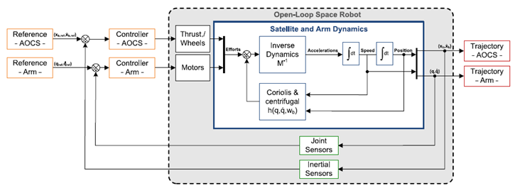
Figure 4 Simulation of the mathematical model for the space robot.6

Space environment and parametric uncertainty

Environmental perturbations

As aforementioned in Sec. 1, the space robot will be subjected to environmental perturbations due to the micro-gravity environment in space; this is mainly due to Gravity Gradient, Aerodynamic Drag, Solar Pressure and Residual Magnetic disturbances. Disturbances observed on the previous missions had a sinusoidal behavior with some fluctuations of varying frequencies. Moreover, these perturbations can be influenced by multiple factors, mainly the orbit parameters of the space robot, solar activities and magnetic storms. Previous data show that the maximum value of these perturbations combined is of the order of magnitude 10-5Nm, however, these data were only correlated to standard satellites.41 Nevertheless, a space robot may encounter different order of magnitude of these perturbations due to their bigger size and its robotic manipulator, which acts as a gravity boom during operation; therefore, it increases the effects of the gravity gradient tremendously. In fact, data from the Japanese spacecraft ETS VII that was equipped with a 2m long robotic arm showed that these disturbances are significantly larger than those experienced by a typical spacecraft. The order of magnitude of perturbations experienced by the ETS VII was in the order of ~10-6→10-3Nm.This is 100 times bigger than what the typical spacecraft encounters.41 Therefore, based on these data, the external disturbances used in this paper for simulations are sinusoidal waves with a Gaussian random noise of zero mean. In addition, the magnitude of the disturbances used here are 3 order of magnitudes higher than the ones observed in previous space missions. This allows for a good margin of safety and testing the proposed control algorithms' limits and robustness against these huge disturbances. Table 2 gives a breakdown of the external disturbances used and their corresponding parameters. The characteristics of the disturbances acting on the thrusters are shown in Figure 5. Furthermore, the same disturbances are imposed on the reaction wheels and joint motors but with a different order of magnitude.


         Sinusoidal

Gaussian Random Noises


Magnitude

Frequency

Mean       

Standard Deviation

Disturbance Forces on Thrusters

0.8

2 rad/s

0

0.1

Disturbance Moments on Reaction Wheels

0.4

2 rad/s

0

0.08

Disturbance Moments on Joint Motors

0.1

2 rad/s

0

0.03

Table 2 External environmental perturbations used in simulation

Mass [kg]

Length [m]

Width [m]

Height [m]

Principal Moments of Inertia [kg m2]

200

1

1

1

[40,40,40]

Table 3 Base-spacecraft specifications
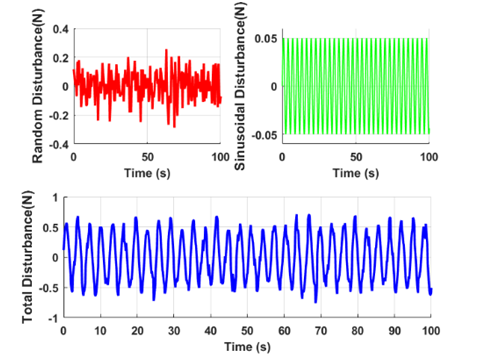
Figure 5 External perturbations on the Thrusters.

Parametric uncertainty

In practical robotic systems, the parameters of the system cannot be known a priori. For example, the load may vary while performing various operations; thus, varying the friction coefficient in different configurations. Moreover, some neglected non-linearities, such as backlash, may introduce disturbances to the control action. Therefore, it is crucial to consider the effects of internal parametric uncertainty on the model.42 Internal disturbances may be caused by any uncertainties in the D or C matrices due to any unmodeled parametric changes in the system. For example, any uncertainty in computing the actual fuel consumption may result in major internal disturbances that will affect the system's performance.42 Accordingly, the additional internal disturbances imposed on the system can be written as:

[ Δ F sc Δ τ sc Δ τ m ]=[ Δ D sc Δ D sc.m Δ D sc.m T Δ D m ][ X ¨ θ ¨ ]+[ Δ C sc     Δ C sc.m Δ C sc.m T Δ C m ][ X θ ˙ ̇ ] MathType@MTEF@5@5@+= feaagKart1ev2aaatCvAUfeBSjuyZL2yd9gzLbvyNv2CaerbuLwBLn hiov2DGi1BTfMBaeXatLxBI9gBaerbd9wDYLwzYbItLDharqqtubsr 4rNCHbGeaGqkY=Mj0xXdbba91rFfpec8Eeeu0xXdbba9frFj0=OqFf ea0dXdd9vqaq=JfrVkFHe9pgea0dXdar=Jb9hs0dXdbPYxe9vr0=vr 0=vqpWqaaeaabiGaciaacaqabeaadaqaaqaaaOqaaabaaaaaaaaape WaamWaa8aabaqbaeqabmqaaaqaaGGac8qacqWFuoarieWacaGFgbWd amaaBaaaleaapeGaa43Caiaa+ngaa8aabeaaaOqaa8qacqqHuoarcq aHepaDpaWaaSbaaSqaa8qacaGFZbGaa43yaaWdaeqaaaGcbaWdbiab fs5aejabes8a09aadaWgaaWcbaWdbiaa+1gaa8aabeaaaaaak8qaca GLBbGaayzxaaGaeyypa0ZaamWaa8aabaqbaeqabiGaaaqaa8qacqWF uoarcaWHebWdamaaBaaaleaapeGaaC4Caiaahogaa8aabeaaaOqaa8 qacqWFuoarcaWHebWdamaaBaaaleaapeGaaC4CaiaahogacaGGUaGa aCyBaaWdaeqaaaGcbaWdbiab=r5aejaahseapaWaa0baaSqaa8qaca WHZbGaaC4yaiaac6cacaWHTbaapaqaa8qacaWHubaaaaGcpaqaa8qa cqWFuoarcaWHebWdamaaBaaaleaapeGaaCyBaaWdaeqaaaaaaOWdbi aawUfacaGLDbaadaWadaWdaeaafaqabeGabaaabaWdbiqa+HfapaGb amaaaeaapeGafqiUde3dayaadaaaaaWdbiaawUfacaGLDbaacqGHRa WkdaWadaWdaeaafaqabeGabaaabaqbaeqabeGaaaqaa8qacqWFuoar caWHdbWdamaaBaaaleaapeGaaC4Caiaahogaa8aabeaaaOqaa8qaca GGGcGaaiiOaiaacckacaGGGcGae8hLdqKaaC4qa8aadaWgaaWcbaWd biaahohacaWHJbGaaiOlaiaah2gaa8aabeaaaaaakeaapeGae8hLdq 0dauaabeqabiaaaeaapeGaaC4qa8aadaqhaaWcbaWdbiaahohacaWH JbGaaiOlaiaah2gaa8aabaWdbiaahsfaaaaak8aabaWdbiab=r5aej aahoeapaWaaSbaaSqaa8qacaWHTbaapaqabaaaaaaaaOWdbiaawUfa caGLDbaadaWadaWdaeaadaWfGaqaauaabeqaceaaaeaapeGaamiwaa WdaeaapeGafqiUde3dayaacaaaaaWcbeqaa8qacqWIhmGjaaaakiaa wUfacaGLDbaaaaa@88CB@ (7.1)

In this paper, for simulation purpose, the internal disturbance due to the uncertainty in fuel consumption was considered and this will, in turn, produce a change in the Dsc and Csc matrices. Therefore, it produces a force and moment that will alter the linear and angular motion of the base-spacecraft. Thus, the above equation can be re-written as:

[ Δ F sc Δ τ Sc ]=Δ D sc   X ¨ +Δ C sc   X ˙ MathType@MTEF@5@5@+= feaagKart1ev2aqatCvAUfeBSjuyZL2yd9gzLbvyNv2CaerbuLwBLn hiov2DGi1BTfMBaeXatLxBI9gBaerbd9wDYLwzYbItLDharqqtubsr 4rNCHbGeaGqkY=Mj0xXdbba91rFfpec8Eeeu0xXdbba9frFj0=OqFf ea0dXdd9vqaq=JfrVkFHe9pgea0dXdar=Jb9hs0dXdbPYxe9vr0=vr 0=vqpWqaaeaabiGaciaacaqabeaadaqaaqaaaOqaaabaaaaaaaaape WaamWaa8aabaqbaeqabiqaaaqaa8qacqqHuoarieWacaWFgbWdamaa BaaaleaapeGaa83Caiaa=ngaa8aabeaaaOqaa8qacqqHuoarcqaHep aDpaWaaSbaaSqaa8qacaWFtbGaa83yaaWdaeqaaaaaaOWdbiaawUfa caGLDbaacqGH9aqpiiGacqGFuoarcaWHebWdamaaBaaaleaapeGaaC 4Caiaahogaa8aabeaak8qacaWFGcGab8hwa8aagaWaa8qacqGHRaWk cqGFuoarcaWHdbWdamaaBaaaleaapeGaaC4Caiaahogaa8aabeaak8 qacaWFGcGab8hwa8aagaGaaaaa@5261@ (7.2)

Based on equation (7.2), the dependency of these internal disturbances on the states of the system which are changed by the control algorithm is apparent. Therefore, each simulation is going to have different internal disturbances imposed. Results in Figure 6 are obtained from the Control-Floating mode simulation over 100 s. It shows the effects of the uncertainty in fuel consumption, which accordingly will change the mass of the spacecraft and in turn produce internal disturbances on the system. It can be seen that these disturbances also follow a cyclic behavior due to the imposed external disturbance on the system as discussed in Sec. 7.1.
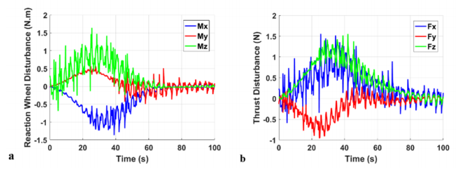
Figure 6 Internal Disturbances due to parametric uncertainties: (a) on Thrusters, (b) on RW.

Control system design for a space robot

In this section, a 3-stage control algorithm is presented for the space robot. The first stage would be feed-forward compensation to decouple the space robot system into a 6 DOF robotic manipulator and a 6 DOF base-spacecraft. It also compensates for the dynamic coupling reaction forces and moments between the two decoupled systems. The second stage would be feed-forward linearization using a non-linear controller to linearize both decoupled non-linear systems. The third and final stage of control will be to design a linear PID or LQR controller for the linearized de-coupled systems. The step-by-step process for designing the controller is described here below:

Feed-forward compensation

As stated in Section 5.2.1, to decouple the system, feed-forward compensation should be used to mitigate the effects of the D sc.m MathType@MTEF@5@5@+= feaagKart1ev2aaatCvAUfeBSjuyZL2yd9gzLbvyNv2CaerbuLwBLn hiov2DGi1BTfMBaeXatLxBI9gBaerbd9wDYLwzYbItLDharqqtubsr 4rNCHbGeaGqkY=Mj0xXdbba91rFfpec8Eeeu0xXdbba9frFj0=OqFf ea0dXdd9vqaq=JfrVkFHe9pgea0dXdar=Jb9hs0dXdbPYxe9vr0=vr 0=vqpWqaaeaabiGaciaacaqabeaadaqaaqaaaOqaaKqzGeaeaaaaaa aaa8qacaWHebGcdaWgaaWcbaWdamaaBaaameaajugWa8qacaWHZbGa aC4yaiaac6cacaWHTbaam8aabeaaaSWdbeqaaaaa@3E00@ and C sc.m MathType@MTEF@5@5@+= feaagKart1ev2aaatCvAUfeBSjuyZL2yd9gzLbvyNv2CaerbuLwBLn hiov2DGi1BTfMBaeXatLxBI9gBaerbd9wDYLwzYbItLDharqqtubsr 4rNCHbGeaGqkY=Mj0xXdbba91rFfpec8Eeeu0xXdbba9frFj0=OqFf ea0dXdd9vqaq=JfrVkFHe9pgea0dXdar=Jb9hs0dXdbPYxe9vr0=vr 0=vqpWqaaeaabiGaciaacaqabeaadaqaaqaaaOqaaKqzGeaeaaaaaa aaa8qacaWHdbWcpaWaaSbaaeaajugWa8qacaWHZbGaaC4yaiacycOG UaGaialGh2gaaSWdaeqaaaaa@4004@ terms, as follows:

[ F s c FFC τ s c FFC τ m FFC ]=[ 0 D sc.m D sc.m T 0 ][ X ¨ θ ¨ ]+[ 0 C sc.m C sc.m T 0 ][ X θ ˙ ̇ ] MathType@MTEF@5@5@+= feaagKart1ev2aaatCvAUfeBSjuyZL2yd9gzLbvyNv2CaerbuLwBLn hiov2DGi1BTfMBaeXatLxBI9gBaerbd9wDYLwzYbItLDharqqtubsr 4rNCHbGeaGqkY=Mj0xXdbba91rFfpec8Eeeu0xXdbba9frFj0=OqFf ea0dXdd9vqaq=JfrVkFHe9pgea0dXdar=Jb9hs0dXdbPYxe9vr0=vr 0=vqpWqaaeaabiGaciaacaqabeaadaqaaqaaaOqaaabaaaaaaaaape WaamWaa8aabaqbaeqabmqaaaqaaGqad8qacaWFgbWdamaaBaaaleaa peGaa83Caiaa=ngapaWaaSbaaWqaa8qacaWFgbGaa8Nraiaa=neaa8 aabeaaaSqabaaakeaapeGaeqiXdq3damaaBaaaleaapeGaa83Caiaa =ngapaWaaSbaaWqaa8qacaWFgbGaa8Nraiaa=neaa8aabeaaaSqaba aakeaapeGaeqiXdq3damaaBaaaleaapeGaa8xBa8aadaWgaaadbaWd biaa=zeacaWFgbGaa83qaaWdaeqaaaWcbeaaaaaak8qacaGLBbGaay zxaaGaeyypa0ZaamWaa8aabaqbaeqabiGaaaqaa8qacaaIWaaapaqa a8qacaWHebWdamaaBaaaleaapeGaaC4CaiaahogacaGGUaGaaCyBaa WdaeqaaaGcbaWdbiaahseapaWaa0baaSqaa8qacaWHZbGaaC4yaiaa c6cacaWHTbaapaqaa8qacaWHubaaaaGcpaqaa8qacaaIWaaaaaGaay 5waiaaw2faamaadmaapaqaauaabeqaceaaaeaapeGab8hwa8aagaWa aaqaa8qacuaH4oqCpaGbamaaaaaapeGaay5waiaaw2faaiabgUcaRm aadmaapaqaauaabeqaceaaaeaafaqabeqacaaabaWdbiaaicdaa8aa baWdbiaahoeapaWaaSbaaSqaa8qacaWHZbGaaC4yaiaac6cacaWHTb aapaqabaaaaaGcbaqbaeqabeGaaaqaa8qacaWHdbWdamaaDaaaleaa peGaaC4CaiaahogacaGGUaGaaCyBaaWdaeaapeGaaCivaaaaaOWdae aapeGaaGimaaaaaaaacaGLBbGaayzxaaWaamWaa8aabaWaaCbiaeaa faqabeGabaaabaWdbiaadIfaa8aabaWdbiqbeI7aX9aagaGaaaaaaS qabeaapeGaeS4bdycaaaGccaGLBbGaayzxaaaaaa@754E@ (8.1)

Hence, after applying the feed-forward compensation, the 12-DoF space robot system is decoupled into a 6 DOF base-spacecraft and a 6 DOF robotic manipulator. This decoupled system can be as follows:

[ F sc τ sc τ m ]=[ D sc 0 0 D m ][ X ¨ θ ¨ ]+[ C sc 0 0 C m ][ X θ ˙ ̇ ] MathType@MTEF@5@5@+= feaagKart1ev2aqatCvAUfeBSjuyZL2yd9gzLbvyNv2CaerbuLwBLn hiov2DGi1BTfMBaeXatLxBI9gBaerbd9wDYLwzYbItLDharqqtubsr 4rNCHbGeaGqkY=Mj0xXdbba91rFfpec8Eeeu0xXdbba9frFj0=OqFf ea0dXdd9vqaq=JfrVkFHe9pgea0dXdar=Jb9hs0dXdbPYxe9vr0=vr 0=vqpWqaaeaabiGaciaacaqabeaadaqaaqaaaOqaaabaaaaaaaaape WaamWaa8aabaqbaeqabmqaaaqaaGqad8qacaWFgbWdamaaBaaaleaa peGaa83Caiaa=ngaa8aabeaaaOqaa8qacqaHepaDpaWaaSbaaSqaa8 qacaWFZbGaa83yaaWdaeqaaaGcbaWdbiabes8a09aadaWgaaWcbaWd biaa=1gaa8aabeaaaaaak8qacaGLBbGaayzxaaGaeyypa0ZaamWaa8 aabaqbaeqabiGaaaqaa8qacaWHebWdamaaBaaaleaapeGaaC4Caiaa hogaa8aabeaaaOqaa8qacaaIWaaapaqaa8qacaaIWaaapaqaa8qaca WHebWdamaaBaaaleaapeGaaCyBaaWdaeqaaaaaaOWdbiaawUfacaGL DbaadaWadaWdaeaafaqabeGabaaabaWdbiqa=HfapaGbamaaaeaape GafqiUde3dayaadaaaaaWdbiaawUfacaGLDbaacqGHRaWkdaWadaWd aeaafaqabeGabaaabaqbaeqabeGaaaqaa8qacaWHdbWdamaaBaaale aapeGaaC4Caiaahogaa8aabeaaaOqaa8qacaaIWaaaaaWdaeaafaqa beqacaaabaWdbiaaicdaa8aabaWdbiaahoeapaWaaSbaaSqaa8qaca WHTbaapaqabaaaaaaaaOWdbiaawUfacaGLDbaadaWadaWdaeaadaWf GaqaauaabeqaceaaaeaapeGaamiwaaWdaeaapeGafqiUde3dayaaca aaaaWcbeqaa8qacqWIhmGjaaaakiaawUfacaGLDbaaaaa@6314@ (8.2)

As seen from equation (8.2), the mutual dynamic coupling is eliminated by removing the terms D sc.m MathType@MTEF@5@5@+= feaagKart1ev2aaatCvAUfeBSjuyZL2yd9gzLbvyNv2CaerbuLwBLn hiov2DGi1BTfMBaeXatLxBI9gBaerbd9wDYLwzYbItLDharqqtubsr 4rNCHbGeaGqkY=Mj0xXdbba91rFfpec8Eeeu0xXdbba9frFj0=OqFf ea0dXdd9vqaq=JfrVkFHe9pgea0dXdar=Jb9hs0dXdbPYxe9vr0=vr 0=vqpWqaaeaabiGaciaacaqabeaadaqaaqaaaOqaaKqzGeaeaaaaaa aaa8qacaWHebGcdaWgaaWcbaWdamaaBaaameaajugWa8qacaWHZbGa aC4yaiaac6cacaWHTbaam8aabeaaaSWdbeqaaaaa@3E00@ and C sc.m MathType@MTEF@5@5@+= feaagKart1ev2aaatCvAUfeBSjuyZL2yd9gzLbvyNv2CaerbuLwBLn hiov2DGi1BTfMBaeXatLxBI9gBaerbd9wDYLwzYbItLDharqqtubsr 4rNCHbGeaGqkY=Mj0xXdbba91rFfpec8Eeeu0xXdbba9frFj0=OqFf ea0dXdd9vqaq=JfrVkFHe9pgea0dXdar=Jb9hs0dXdbPYxe9vr0=vr 0=vqpWqaaeaabiGaciaacaqabeaadaqaaqaaaOqaaKqzGeaeaaaaaa aaa8qacaWHdbWcpaWaaSbaaeaajugWa8qacaWHZbGaaC4yaiacycOG UaGaialGh2gaaSWdaeqaaaaa@4004@ from the dynamics equation.

Feed-forward linearization

The dynamic model obtained using feed-forward compensation in equation (8.2) is still very complex, extremely dynamic and non-linear in nature. Hence, a linear PID or LQR controller cannot guarantee the stability of the closed-loop system. Therefore, to solve this issue, the feed-forward linearization technique is applied after the feed-forward compensation process to linearize the decoupled systems. This allows the use of a LQR or PID controller in the final stage. The control law for feed-forward linearization is expressed as follows:

[ F s c FFL τ s c FFL τ m FFL ]=[ D sc 0 0 D m ][ F sc Linear τ sc Linear τ m Linear ]+[ C sc 0 0 C m ][ X θ ˙ ̇ ] MathType@MTEF@5@5@+= feaagKart1ev2aqatCvAUfeBSjuyZL2yd9gzLbvyNv2CaerbuLwBLn hiov2DGi1BTfMBaeXatLxBI9gBaerbd9wDYLwzYbItLDharqqtubsr 4rNCHbGeaGqkY=Mj0xXdbba91rFfpec8Eeeu0xXdbba9frFj0=OqFf ea0dXdd9vqaq=JfrVkFHe9pgea0dXdar=Jb9hs0dXdbPYxe9vr0=vr 0=vqpWqaaeaabiGaciaacaqabeaadaqaaqaaaOqaaabaaaaaaaaape WaamWaa8aabaqbaeqabmqaaaqaaGqad8qacaWFgbWdamaaBaaaleaa peGaa83Caiaa=ngapaWaaSbaaWqaa8qacaWFgbGaa8Nraiaa=Xeaa8 aabeaaaSqabaaakeaapeGaeqiXdq3damaaBaaaleaapeGaa83Caiaa =ngapaWaaSbaaWqaa8qacaWFgbGaa8Nraiaa=Xeaa8aabeaaaSqaba aakeaapeGaeqiXdq3damaaBaaaleaapeGaa8xBa8aadaWgaaadbaWd biaa=zeacaWFgbGaa8htaaWdaeqaaaWcbeaaaaaak8qacaGLBbGaay zxaaGaeyypa0ZaamWaa8aabaqbaeqabiGaaaqaa8qacaWHebWdamaa BaaaleaapeGaaC4Caiaahogaa8aabeaaaOqaa8qacaaIWaaapaqaa8 qacaaIWaaapaqaa8qacaWHebWdamaaBaaaleaapeGaaCyBaaWdaeqa aaaaaOWdbiaawUfacaGLDbaadaWadaWdaeaafaqabeWabaaabaWdbi aa=zeapaWaaSbaaSqaa8qacaWFZbGaa83yaaWdaeqaaOWaaSbaaSqa a8qacaWFmbGaa8xAaiaa=5gacaWFLbGaa8xyaiaa=jhaa8aabeaaaO qaa8qacqaHepaDpaWaaSbaaSqaa8qacaWFZbGaa83yaaWdaeqaaOWa aSbaaSqaa8qacaWFmbGaa8xAaiaa=5gacaWFLbGaa8xyaiaa=jhaa8 aabeaaaOqaa8qacqaHepaDpaWaaSbaaSqaa8qacaWFTbaapaqabaGc daWgaaWcbaWdbiaa=XeacaWFPbGaa8NBaiaa=vgacaWFHbGaa8NCaa WdaeqaaaaaaOWdbiaawUfacaGLDbaacqGHRaWkdaWadaWdaeaafaqa beGabaaabaqbaeqabeGaaaqaa8qacaWHdbWdamaaBaaaleaapeGaaC 4Caiaahogaa8aabeaaaOqaa8qacaaIWaaaaaWdaeaafaqabeqacaaa baWdbiaaicdaa8aabaWdbiaahoeapaWaaSbaaSqaa8qacaWHTbaapa qabaaaaaaaaOWdbiaawUfacaGLDbaadaWadaWdaeaadaWfGaqaauaa beqaceaaaeaapeGaamiwaaWdaeaapeGafqiUde3dayaacaaaaaWcbe qaa8qacqWIhmGjaaaakiaawUfacaGLDbaaaaa@83B8@ (8.3)

Using equation (8.3) in (8.2):

[ F sc Linear τ sc Linear τ m Linear ]=[ X ¨ θ ¨ ] MathType@MTEF@5@5@+= feaagKart1ev2aqatCvAUfeBSjuyZL2yd9gzLbvyNv2CaerbuLwBLn hiov2DGi1BTfMBaeXatLxBI9gBaerbd9wDYLwzYbItLDharqqtubsr 4rNCHbGeaGqkY=Mj0xXdbba91rFfpec8Eeeu0xXdbba9frFj0=OqFf ea0dXdd9vqaq=JfrVkFHe9pgea0dXdar=Jb9hs0dXdbPYxe9vr0=vr 0=vqpWqaaeaabiGaciaacaqabeaadaqaaqaaaOqaaabaaaaaaaaape WaamWaa8aabaqbaeqabmqaaaqaaGqad8qacaWFgbWdamaaBaaaleaa peGaa83Caiaa=ngaa8aabeaakmaaBaaaleaapeGaa8htaiaa=Lgaca WFUbGaa8xzaiaa=fgacaWFYbaapaqabaaakeaapeGaeqiXdq3damaa BaaaleaapeGaa83Caiaa=ngaa8aabeaakmaaBaaaleaapeGaa8htai aa=LgacaWFUbGaa8xzaiaa=fgacaWFYbaapaqabaaakeaapeGaeqiX dq3damaaBaaaleaapeGaa8xBaaWdaeqaaOWaaSbaaSqaa8qacaWFmb Gaa8xAaiaa=5gacaWFLbGaa8xyaiaa=jhaa8aabeaaaaaak8qacaGL BbGaayzxaaGaeyypa0ZaamWaa8aabaqbaeqabiqaaaqaa8qaceWFyb WdayaadaaabaWdbiqbeI7aX9aagaWaaaaaa8qacaGLBbGaayzxaaaa aa@5ACD@ (8.4)

Therefore, as seen from equation (8.4), feed-forward linearization results in a simple, decoupled-linear system that can be further controlled using conventional LQR or PID controllers.

PID controller

As discussed in Section 5.2.2, conventional PID controllers are not the best choice when it comes to controlling a space robot due to its high complexity, non-linearity and limited robustness to both external perturbations and model uncertainties. Thus, the PID controller will be used only in the final stage of the three-stage control algorithm presented. In addition, this staging method allows tuning the gains of the PID controller using the characteristic equation of the linearized-decoupled systems, therefore, gaining much better performance as a result of choosing accurate gain values. The PID linear controller, which represents the third stage of the control algorithm, can be expressed as:

[ F sc Linear τ sc Linear τ m Linear ]=[ X ¨ Desired θ ¨ Desired ]+ K p [ X Desired X θ Desired θ ]+ K d [ X ˙ Desired X ˙ θ ˙ Desired θ ˙ ]+ K i  [ X Desired X θ Desired θ ] MathType@MTEF@5@5@+= feaagKart1ev2aqatCvAUfeBSjuyZL2yd9gzLbvyNv2CaerbuLwBLn hiov2DGi1BTfMBaeXatLxBI9gBaerbd9wDYLwzYbItLDharqqtubsr 4rNCHbGeaGqkY=Mj0xXdbba91rFfpec8Eeeu0xXdbba9frFj0=OqFf ea0dXdd9vqaq=JfrVkFHe9pgea0dXdar=Jb9hs0dXdbPYxe9vr0=vr 0=vqpWqaaeaabiGaciaacaqabeaadaqaaqaaaOqaaabaaaaaaaaape WaamWaa8aabaqbaeqabmqaaaqaaGqad8qacaWFgbWdamaaBaaaleaa peGaa83Caiaa=ngaa8aabeaakmaaBaaaleaapeGaa8htaiaa=Lgaca WFUbGaa8xzaiaa=fgacaWFYbaapaqabaaakeaapeGaeqiXdq3damaa BaaaleaapeGaa83Caiaa=ngaa8aabeaakmaaBaaaleaapeGaa8htai aa=LgacaWFUbGaa8xzaiaa=fgacaWFYbaapaqabaaakeaapeGaeqiX dq3damaaBaaaleaapeGaa8xBaaWdaeqaaOWaaSbaaSqaa8qacaWFmb Gaa8xAaiaa=5gacaWFLbGaa8xyaiaa=jhaa8aabeaaaaaak8qacaGL BbGaayzxaaGaeyypa0ZaamWaa8aabaqbaeqabiqaaaqaa8qaceWFyb WdayaadaWaaSbaaSqaa8qacaWFebGaa8xzaiaa=nhacaWFPbGaa8NC aiaa=vgacaWFKbaapaqabaaakeaapeGafqiUde3dayaadaWaaSbaaS qaa8qacaWFebGaa8xzaiaa=nhacaWFPbGaa8NCaiaa=vgacaWFKbaa paqabaaaaaGcpeGaay5waiaaw2faaiabgUcaRiaa=TeapaWaaSbaaS qaa8qacaWFWbaapaqabaGcpeWaamWaa8aabaqbaeqabiqaaaqaa8qa caWFybWdamaaBaaaleaapeGaa8hraiaa=vgacaWFZbGaa8xAaiaa=j hacaWFLbGaa8hzaaWdaeqaaOWdbiabgkHiTiaadIfaa8aabaWdbiab eI7aX9aadaWgaaWcbaWdbiaa=reacaWFLbGaa83Caiaa=LgacaWFYb Gaa8xzaiaa=rgaa8aabeaak8qacqGHsislcqaH4oqCaaaacaGLBbGa ayzxaaGaey4kaSIaa83sa8aadaWgaaWcbaWdbiaa=rgaa8aabeaak8 qadaWadaWdaeaafaqabeGabaaabaWdbiqa=HfapaGbaiaadaWgaaWc baWdbiaa=reacaWFLbGaa83Caiaa=LgacaWFYbGaa8xzaiaa=rgaa8 aabeaak8qacqGHsislceWFybWdayaacaaabaWdbiqbeI7aX9aagaGa amaaBaaaleaapeGaa8hraiaa=vgacaWFZbGaa8xAaiaa=jhacaWFLb Gaa8hzaaWdaeqaaOWdbiabgkHiTiqbeI7aX9aagaGaaaaaa8qacaGL BbGaayzxaaGaey4kaSIaa83sa8aadaWgaaWcbaWdbiaa=LgacaWFGc aapaqabaGcdaqfGaqabSqabeaacaaMb8oaneaapeGaey4kIipaaOWa amWaa8aabaqbaeqabiqaaaqaa8qacaWFybWdamaaBaaaleaapeGaa8 hraiaa=vgacaWFZbGaa8xAaiaa=jhacaWFLbGaa8hzaaWdaeqaaOWd biabgkHiTiaadIfaa8aabaWdbiabeI7aX9aadaWgaaWcbaWdbiaa=r eacaWFLbGaa83Caiaa=LgacaWFYbGaa8xzaiaa=rgaa8aabeaak8qa cqGHsisliiGacqGF4oqCaaaacaGLBbGaayzxaaaaaa@BA53@ (8.5)

Figure 7 shows the implementation of the 3-stage control algorithm with a PID controller in its final stage. It shows the feed-forward compensation scheme to eliminate the dynamic coupling reactions that are computed based on the reading of the joint sensors of the manipulator. It is fed-forward, in real-time, to the spacecraft motion controller for counteracting these effects. Furthermore, saturation blocks are added to limit the control output within the practical limits of the actuation system on-board the spacecraft.
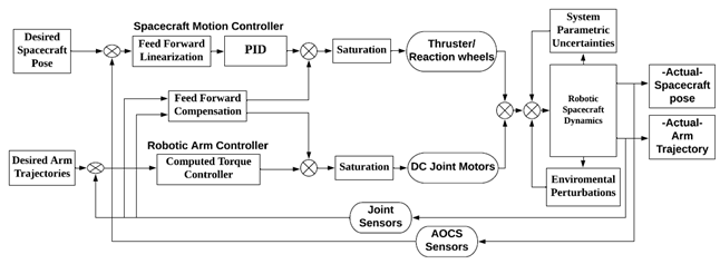
Figure 7 Control scheme using the PID as a final stage controller.

LQR controller

The LQR controller is based on state feedback and its gains are determined based on the trade-off between transient performance and control effort. Thus, the optimal control approach43 to this trade-off is to define and minimize the cost function. Furthermore, since the robot generally has to reach a non-zero target position and attitude, a non-zero set point optimal control44 has been considered. This enables the controller to follow the desired trajectory by shifting the actual state x( t )=[ X θ ] MathType@MTEF@5@5@+= feaagKart1ev2aqatCvAUfeBSjuyZL2yd9gzLbvyNv2CaerbuLwBLn hiov2DGi1BTfMBaeXatLxBI9gBaerbd9wDYLwzYbItLDharqqtubsr 4rNCHbGeaGqkY=Mj0xXdbba91rFfpec8Eeeu0xXdbba9frFj0=OqFf ea0dXdd9vqaq=JfrVkFHe9pgea0dXdar=Jb9hs0dXdbPYxe9vr0=vr 0=vqpWqaaeaabiGaciaacaqabeaadaqaaqaaaOqaaGqadKqzGeaeaa aaaaaaa8qacaWF4bGcdaqadaWdaeaajugib8qacaWF0baakiaawIca caGLPaaajugibiabg2da9OWaamWaa8aabaqcLbsapeGaa8hwaiaabc caiiWacqGF4oqCaOGaay5waiaaw2faaaaa@4385@ by a desired quantity x d MathType@MTEF@5@5@+= feaagKart1ev2aqatCvAUfeBSjuyZL2yd9gzLbvyNv2CaerbuLwBLn hiov2DGi1BTfMBaeXatLxBI9gBaerbd9wDYLwzYbItLDharqqtubsr 4rNCHbGeaGqkY=Mj0xXdbba91rFfpec8Eeeu0xXdbba9frFj0=OqFf ea0dXdd9vqaq=JfrVkFHe9pgea0dXdar=Jb9hs0dXdbPYxe9vr0=vr 0=vqpWqaaeaabiGaciaacaqabeaadaqaaqaaaOqaaGqadKqzGeaeaa aaaaaaa8qacaWF4bGcdaWgaaWcbaWdamaaBaaameaapeGaiair=rga a8aabeaaaSWdbeqaaaaa@3B20@ , thus obtaining the error, defined as:

x e ( t )= x d ( t )x( t ) MathType@MTEF@5@5@+= feaagKart1ev2aqatCvAUfeBSjuyZL2yd9gzLbvyNv2CaerbuLwBLn hiov2DGi1BTfMBaeXatLxBI9gBaerbd9wDYLwzYbItLDharqqtubsr 4rNCHbGeaGqkY=Mj0xXdbba91rFfpec8Eeeu0xXdbba9frFj0=OqFf ea0dXdd9vqaq=JfrVkFHe9pgea0dXdar=Jb9hs0dXdbPYxe9vr0=vr 0=vqpWqaaeaabiGaciaacaqabeaadaqaaqaaaOqaaGqadKqzGeaeaa aaaaaaa8qacaWF4bGcpaWaaSbaaSqaaKqzadWdbiaa=vgaaSWdaeqa aOWdbmaabmaapaqaaKqzGeWdbiaa=rhaaOGaayjkaiaawMcaaKqzGe Gaeyypa0Jaa8hEaSWaaSbaaWqaa8aadaWgaaqaa8qacGaGe9hzaaWd aeqaaaWdbeqaaOWaaeWaa8aabaqcLbsapeGaa8hDaaGccaGLOaGaay zkaaqcLbsacqGHsislcaWF4bGcdaqadaWdaeaajugib8qacaWF0baa kiaawIcacaGLPaaaaaa@4C61@ (8.6)

First, the optimal control problem is solved using the method of calculus of variations. Thus, the control action  u (t) that stabilizes the closed-loop system over a fixed time t f MathType@MTEF@5@5@+= feaagKart1ev2aqatCvAUfeBSjuyZL2yd9gzLbvyNv2CaerbuLwBLn hiov2DGi1BTfMBaeXatLxBI9gBaerbd9wDYLwzYbItLDharqqtubsr 4rNCHbGeaGqkY=Mj0xXdbba91rFfpec8Eeeu0xXdbba9frFj0=OqFf ea0dXdd9vqaq=JfrVkFHe9pgea0dXdar=Jb9hs0dXdbPYxe9vr0=vr 0=vqpWqaaeaabiGaciaacaqabeaadaqaaqaaaOqaaKqzafaeaaaaaa aaa8qacaqG0bGcpaWaaSbaaKGaafaajugab8qacaqGMbaajiaqpaqa baaaaa@3B1C@ whilst minimizing the cost function is given as:

J= 0 t f x ( t ) T Q x( t )+u ( t ) T Ru( t )dt MathType@MTEF@5@5@+= feaagKart1ev2aqatCvAUfeBSjuyZL2yd9gzLbvyNv2CaerbuLwBLn hiov2DGi1BTfMBaeXatLxBI9gBaerbd9wDYLwzYbItLDharqqtubsr 4rNCHbGeaGqkY=Mj0xXdbba91rFfpec8Eeeu0xXdbba9frFj0=OqFf ea0dXdd9vqaq=JfrVkFHe9pgea0dXdar=Jb9hs0dXdbPYxe9vr0=vr 0=vqpWqaaeaabiGaciaacaqabeaadaqaaqaaaOqaaKqzGeaeaaaaaa aaa8qacaqGkbGaeyypa0JcdaGfWbqabSWdaeaajugib8qacaaIWaaa l8aabaqcLbsapeGaaeiDaOWdamaaBaaameaajugWa8qacaqGMbaam8 aabeaaa0qaaKqzGeWdbiabgUIiYdaaieWacaWF4bGcdaqadaWdaeaa jugib8qacaWF0baakiaawIcacaGLPaaapaWaaWbaaSqabeaajugWa8 qacaWFubaaaKqzGeGaaCyuaiaa=bkacaWF4bGcdaqadaWdaeaajugi b8qacaWF0baakiaawIcacaGLPaaajugibiabgUcaRiaa=vhakmaabm aapaqaaKqzGeWdbiaa=rhaaOGaayjkaiaawMcaa8aadaahaaWcbeqa aKqzadWdbiaa=rfaaaqcLbsacaWHsbGaa8xDaOWaaeWaa8aabaqcLb sapeGaa8hDaaGccaGLOaGaayzkaaqcLbsacaWFKbGaa8hDaaaa@5FA1@ (8.7)

As shown in equation (5.7), the cost function is dependent on two terms, the first penalizes the variation of the states from the desired ones, while the second penalizes the use of excessive control action to control the system. Moreover, the weighting of these terms is controlled by the weighting matrices Q MathType@MTEF@5@5@+= feaagKart1ev2aqatCvAUfeBSjuyZL2yd9gzLbvyNv2CaerbuLwBLn hiov2DGi1BTfMBaeXatLxBI9gBaerbd9wDYLwzYbItLDharqqtubsr 4rNCHbGeaGqkY=Mj0xXdbba91rFfpec8Eeeu0xXdbba9frFj0=OqFf ea0dXdd9vqaq=JfrVkFHe9pgea0dXdar=Jb9hs0dXdbPYxe9vr0=vr 0=vqpWqaaeaabiGaciaacaqabeaadaqaaqaaaOqaaKqzGeaeaaaaaa aaa8qacaWHrbaaaa@3898@ and R MathType@MTEF@5@5@+= feaagKart1ev2aqatCvAUfeBSjuyZL2yd9gzLbvyNv2CaerbuLwBLn hiov2DGi1BTfMBaeXatLxBI9gBaerbd9wDYLwzYbItLDharqqtubsr 4rNCHbGeaGqkY=Mj0xXdbba91rFfpec8Eeeu0xXdbba9frFj0=OqFf ea0dXdd9vqaq=JfrVkFHe9pgea0dXdar=Jb9hs0dXdbPYxe9vr0=vr 0=vqpWqaaeaabiGaciaacaqabeaadaqaaqaaaOqaaKqzGeaeaaaaaa aaa8qacaWHsbaaaa@3899@ respectively. In the above terminology, u(t) is the state feedback control law, resulting from the quadratic performance index optimization subjected to the state equations. Q MathType@MTEF@5@5@+= feaagKart1ev2aqatCvAUfeBSjuyZL2yd9gzLbvyNv2CaerbuLwBLn hiov2DGi1BTfMBaeXatLxBI9gBaerbd9wDYLwzYbItLDharqqtubsr 4rNCHbGeaGqkY=Mj0xXdbba91rFfpec8Eeeu0xXdbba9frFj0=OqFf ea0dXdd9vqaq=JfrVkFHe9pgea0dXdar=Jb9hs0dXdbPYxe9vr0=vr 0=vqpWqaaeaabiGaciaacaqabeaadaqaaqaaaOqaaKqzGeaeaaaaaa aaa8qacaWHrbaaaa@3898@ is a positive semi definite state weighting matrix, and R MathType@MTEF@5@5@+= feaagKart1ev2aqatCvAUfeBSjuyZL2yd9gzLbvyNv2CaerbuLwBLn hiov2DGi1BTfMBaeXatLxBI9gBaerbd9wDYLwzYbItLDharqqtubsr 4rNCHbGeaGqkY=Mj0xXdbba91rFfpec8Eeeu0xXdbba9frFj0=OqFf ea0dXdd9vqaq=JfrVkFHe9pgea0dXdar=Jb9hs0dXdbPYxe9vr0=vr 0=vqpWqaaeaabiGaciaacaqabeaadaqaaqaaaOqaaKqzGeaeaaaaaa aaa8qacaWHsbaaaa@3899@ is the control weighting matrix that also has to be positive definite.45 Therefore, the control law is written as:

u( t )=K  x error ( t )  MathType@MTEF@5@5@+= feaagKart1ev2aqatCvAUfeBSjuyZL2yd9gzLbvyNv2CaerbuLwBLn hiov2DGi1BTfMBaeXatLxBI9gBaerbd9wDYLwzYbItLDharqqtubsr 4rNCHbGeaGqkY=Mj0xXdbba91rFfpec8Eeeu0xXdbba9frFj0=OqFf ea0dXdd9vqaq=JfrVkFHe9pgea0dXdar=Jb9hs0dXdbPYxe9vr0=vr 0=vqpWqaaeaabiGaciaacaqabeaadaqaaqaaaOqaaGqadKqzGeaeaa aaaaaaa8qacaWF1bGcdaqadaWdaeaajugib8qacaWF0baakiaawIca caGLPaaajugibiabg2da9iaahUeacaWFGcGaa8hEaOWdamaaBaaale aajugWa8qacaWFLbGaa8NCaiaa=jhacaWFVbGaa8NCaaWcpaqabaGc peWaaeWaa8aabaqcLbsapeGaa8hDaaGccaGLOaGaayzkaaqcLbsaca WFGcaaaa@4BCF@ (8.8)

where K is the state feed-back gain and can be found from:

K= R 1 B T P MathType@MTEF@5@5@+= feaagKart1ev2aqatCvAUfeBSjuyZL2yd9gzLbvyNv2CaerbuLwBLn hiov2DGi1BTfMBaeXatLxBI9gBaerbd9wDYLwzYbItLDharqqtubsr 4rNCHbGeaGqkY=Mj0xXdbba91rFfpec8Eeeu0xXdbba9frFj0=OqFf ea0dXdd9vqaq=JfrVkFHe9pgea0dXdar=Jb9hs0dXdbPYxe9vr0=vr 0=vqpWqaaeaabiGaciaacaqabeaadaqaaqaaaOqaaKqzGeaeaaaaaa aaa8qacaWHlbGaeyypa0JaeyOeI0IaaCOuaOWdamac0bihaaWcbKaD agac0bycLbmapeGamqhGgkHiTiac0biIXaaaaKqzGeGaiWiGhkeal8 aadaahaaqabeaajugWa8qacaWHubaaaKqzGeGaaCiuaaaa@49A5@ (8.9)

and P is the solution of the Algebraic Riccati equation (ARE)

A T P+PAPB R 1 B T P+Q=0 MathType@MTEF@5@5@+= feaagKart1ev2aqatCvAUfeBSjuyZL2yd9gzLbvyNv2CaerbuLwBLn hiov2DGi1BTfMBaeXatLxBI9gBaerbd9wDYLwzYbItLDharqqtubsr 4rNCHbGeaGqkY=Mj0xXdbba91rFfpec8Eeeu0xXdbba9frFj0=OqFf ea0dXdd9vqaq=JfrVkFHe9pgea0dXdar=Jb9hs0dXdbPYxe9vr0=vr 0=vqpWqaaeaabiGaciaacaqabeaadaqaaqaaaOqaaKqzGeaeaaaaaa aaa8qacaWHbbWcpaWaaWbaaeqabaqcLbmapeGaiafMhsfaaaqcLbsa caWHqbGaey4kaSIaaCiuaiaahgeacqGHsislcaWHqbGaaCOqaiaahk fal8aadaahaaqabeaajugWa8qacWaAaAOeI0IaiGgGigdaaaqcLbsa cGaMaEOqaSWdamaaCaaabeqaaKqzadWdbiac0H5HubaaaKqzGeGaaC iuaiabgUcaRiaahgfacqGH9aqpcaaIWaaaaa@52F3@ (8.10)

It is observed that an arbitrarily rapid reduction in the states of the system can be achieved at the expense of a corresponding increase in the control action that can be impossible to implement in practical situations. Moreover, an arbitrarily large reduction in control action may cause a significant elevation of the state and deviation from the desired set points, resulting in an undesirable situation in the attitude control process.46 As a result, the selection of the gains of the LQR control law and the weighting matrices of the LQR is a highly laborious process. Thus, a reasonable choice of Q and R makes the closed-loop system acquire stable performance, while limiting the control action and minimizing fuel expenditure. However, in simulations, the choices of the elements of the Q and R matrices were made based on the diagonal weighting method.It verifes which values best meet the performance criteria such as the overshoot, control effort and settling time; thus, it results in better performance of the system. Like the PID controller, Figure 8 shows the implementation of the LQR controller as a final stage to maintain the space robot's stability.

Figure 8 Control scheme using the LQR as a final stage.

Simulations and discussion

In this section, the performance and robustness of the PID controller is compared against its LQR counterpart for the Free-Flying and Controlled-Floating space robot. The simulations took into account the presence of extreme external disturbances, internal fuel consumption and parametric uncertainties imposed on the system. A fifth-order polynomial function is used to generate smooth trajectories between different set points for both the arm and the base-spacecraft. Additionally, the control action required from the on-board actuation systems is limited to 1→5N for thrusters (like cold or hot gas thrusters) and up to 2N for RWs.48 Since this paper is focused on the close-range approach with the target spacecraft, the orbital parameters are not relevant. Table 4 shows the parameters of the spacecraft, while a standard UR10 robotic arm49 was used in the simulations.

Controller        

Execution Time

PID

0.5 µs

LQR

0.9 µs

Feed-Forward Compensation

0.9 µs

Feed-Forward Linearization

16.5 µs

Over-all Execution Time

21-22 µs

Table 4 Control algorithms execution time

Free-flying space robot

As discussed previously in section 5.1, in this approach, the base-spacecraft tries to maintain stabilization with minimum fluctuations in both position and attitude while the end-effector of the arm follows its desired trajectory to engage with the target spacecraft.

PID results

Simulation results using the PID controller in the Free-Flying approach are shown below. Figure 9 shows the trajectory tracking of the end-effector of the manipulator. It can be seen that the PID controller was able to achieve good trajectory tracking; however, towards the end of the trajectory, the PID could not maintain low level of fluctuations. Nevertheless, the order of magnitude of these variations is still very small and is acceptable for some mission operations. Furthermore, these simulations results are for extreme perturbation environment; therefore, under realistic order of magnitudes for disturbances, the PID is capable of accomplishing perfect tracking throughout the whole trajectory. Moreover, for the relative motion between the Servicer and Target spacecraft during the close-range approach, the PID controller was able to maintain a sinusoidal deviation of maximum 4.7×10⁻⁴m for the relative position and a maximum error of 0.19° MathType@MTEF@5@5@+= feaagKart1ev2aaatCvAUfeBSjuyZL2yd9gzLbvyNv2CaerbuLwBLn hiov2DGi1BTfMBaeXatLxBI9gBaerbd9wDYLwzYbItLDharqqtubsr 4rNCHbGeaGqiVyI8Vfeu0dXdh9vqqj=hEeeu0xXdbba9frpe0=GqFf ea0dXdd9vqaq=JfrVkFHe9pgea0dXdar=Jb9hs0dXdbPYxe9vr0=vr 0=vqpWqaaeaabiGaciaacaqabeaadaqaaqaaaOqaaKqzafGaaGimai aac6cacaaIXaGaaGyoaiadaYLHWcaSaaa@3C0A@ in the relative attitude as shown in Figure 10a & 10c respectively. Additionally, the biggest cyclic deviation is in the 6th joint of the manipulator, which is about 2°3° MathType@MTEF@5@5@+= feaagKart1ev2aaatCvAUfeBSjuyZL2yd9gzLbvyNv2CaerbuLwBLn hiov2DGi1BTfMBaeXatLxBI9gBaerbd9wDYLwzYbItLDharqqtubsr 4rNCHbGeaGqiVyI8Vfeu0dXdh9vqqj=hEeeu0xXdbba9frpe0=GqFf ea0dXdd9vqaq=JfrVkFHe9pgea0dXdar=Jb9hs0dXdbPYxe9vr0=vr 0=vqpWqaaeaabiGaciaacaqabeaadaqaaqaaaOqaaKqzafGaiWiGik dacWaJCziSaaRaeyOeI0IaaG4maiadaYLHWcaSaaa@3F76@ as seen in Figure 10c; this is due to the cumulative effect of external and internal disturbance in the previous five joints. Although this error in the angle is the biggest compared to the other joints, it is still very tolerable in most cases. Moreover, the PID controller was able to maintain the control action under 1N and 1Nm for the thrusters and reactions wheels, as seen in Figure 10d & 10e respectively; this is very realizable for most on-board actuators and more importantly, it saves fuel. Moreover, the control action required was under 1Nm except for the 1st joint, where the maximum control action was about 2Nm; this is due to the total weight and inertia of the arm.
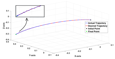
Figure 9 Trajectory Plot for the PID.
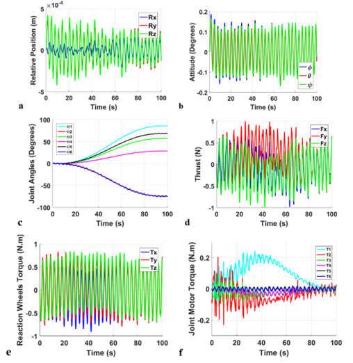
Figure 10 Simulation Results for PID; (a) Relative position, (b) Relative attitude, (c) joint angles, (d) Thrusters force, (e) Reaction Wheels control Toques, (f) Joint Torques.

LQR results

Simulation results for the LQR controller in the Free-Flying approach is shown in Figure 11. Unlike the PID controller, the LQR controller was able to maintain perfect trajectory tracking with infinitesimal fluctuations at the end, as shown in Figure 11a. Therefore, this can be used for high accuracy operations like assembly or mating parts. Moreover, the LQR controller was able to maintain stabilization with a maximum fluctuation of 0.1° MathType@MTEF@5@5@+= feaagKart1ev2aaatCvAUfeBSjuyZL2yd9gzLbvyNv2CaerbuLwBLn hiov2DGi1BTfMBaeXatLxBI9gBaerbd9wDYLwzYbItLDharqqtubsr 4rNCHbGeaGqiVyI8Vfeu0dXdh9vqqj=hEeeu0xXdbba9frpe0=GqFf ea0dXdd9vqaq=JfrVkFHe9pgea0dXdar=Jb9hs0dXdbPYxe9vr0=vr 0=vqpWqaaeaabiGaciaacaqabeaadaqaaqaaaOqaaKqzafGaaGimai aac6cacaaIXaGamaixgclaWcaa@3B47@ for the base spacecraft attitude, as illustrated in Figure 11c. Nevertheless, the deviations in the relative position for the base-spacecraft reached a maximum of 4.7×10⁻⁴m as shown in Figure 11b, which is a little higher than the PID controller was able to achieve. Furthermore, Figure 11d shows that the LQR maintained much lower fluctuations in the 6th joint of the manipulator (less than 0.5° MathType@MTEF@5@5@+= feaagKart1ev2aaatCvAUfeBSjuyZL2yd9gzLbvyNv2CaerbuLwBLn hiov2DGi1BTfMBaeXatLxBI9gBaerbd9wDYLwzYbItLDharqqtubsr 4rNCHbGeaGqiVyI8Vfeu0dXdh9vqqj=hEeeu0xXdbba9frpe0=GqFf ea0dXdd9vqaq=JfrVkFHe9pgea0dXdar=Jb9hs0dXdbPYxe9vr0=vr 0=vqpWqaaeaabiGaciaacaqabeaadaqaaqaaaOqaaKqzafGaaGimai aac6cacaaI1aGamaixgclaWcaa@3B4B@ ), unlike the cyclic 2° MathType@MTEF@5@5@+= feaagKart1ev2aaatCvAUfeBSjuyZL2yd9gzLbvyNv2CaerbuLwBLn hiov2DGi1BTfMBaeXatLxBI9gBaerbd9wDYLwzYbItLDharqqtubsr 4rNCHbGeaGqiVyI8Vfeu0dXdh9vqqj=hEeeu0xXdbba9frpe0=GqFf ea0dXdd9vqaq=JfrVkFHe9pgea0dXdar=Jb9hs0dXdbPYxe9vr0=vr 0=vqpWqaaeaabiGaciaacaqabeaadaqaaqaaaOqaaKqzafGaaGOmai adaYLHWcaSaaa@39DC@ variations obtained with the PID controller. However, although the LQR controller has higher accuracy and robustness to perturbations, it required more fuel. Figure 11e shows that the maximum control action for the thrust was 50% more than its PID counterpart, therefore, reducing the mission lifetime of the space robot. Additionally, as seen in Figure 11a the maximum control action required from the joint motors is 0.6Nm which is 3 times larger; however, this can be still achieved by commercial space qualified motors. Nevertheless, both controllers can be equipped with similar reaction wheels since they demand a similar level of internal torques, as depicted in Figure 11b.
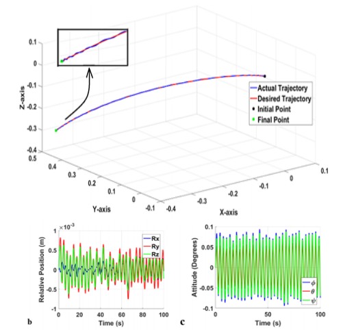
Figure 11 Simulation Results for LQR; (a) Trajectory Plot, (b) relative position, (c) relative attitude, (d) joint angles, (e) Thrusters, (f) Reaction Wheels, (g) Joint Motor.

Controlled-floating space robot

Unlike the Free-Flying approach, the controlled-floating mode allows the base-spacecraft to move and rotate in a controlled manner to match translational and angular rates with the target spacecraft. This is suitable for more sophisticated missions that need precise operations. The trajectory of the base can even be designed in such a manner to minimize dynamic coupling and fuel consumption using the Disturbance Map explained by Vafa and Dubowsky in.14 However, this paper is not focused on the trajectory planning and instead, a 5th order polynomial function is used to generate a trajectory of both the attitude and position of the base-spacecraft between two set points. This choice took into account real-time scenarios where the space robot has to match its rates with the target spacecraft.

PID results

Simulation results using the PID controller in the Controlled-Floating approach are discussed  below. Figure 12a shows the resulting 3D trajectory tracking graph for the end-effector of the manipulator. The PID controller was able to maintain perfect tracking of the desired trajectory without any cross-track errors or fluctuations along the path. Figure 12b & 12c shows the actual relative position and attitude trajectories being followed by the base-spacecraft to attain the orientation and position with respect to the target whilst maintaining 1m distance to avoid any collisions. However, Figure 12c shows some small fluctuations in ϕ till the steady state value is reached. Similar to the Free-Flying case, Figure 13a shows some minor fluctuations of 2° MathType@MTEF@5@5@+= feaagKart1ev2aqatCvAUfeBSjuyZL2yd9gzLbvyNv2CaerbuLwBLn hiov2DGi1BTfMBaeXatLxBI9gBaerbd9wDYLwzYbItLDharqqtubsr 4rNCHbGeaGqkY=Mj0xXdbba91rFfpec8Eeeu0xXdbba9frFj0=OqFf ea0dXdd9vqaq=JfrVkFHe9pgea0dXdar=Jb9hs0dXdbPYxe9vr0=vr 0=vqpWqaaeaabiGaciaacaqabeaadaqaaqaaaOqaaKqzGeGaaGOmai adaYLHWcaSaaa@3B2A@ on the 6th joint of the manipulator; this is an acceptable level of accuracy for some missions. It is important to recall that these simulated results are for extreme environmental disturbances but under realistic micro-gravity environment, these responses will be much smoother and accurate. The extreme cases are considered here mainly to test the limits of the control algorithms used. As shown in Figure 13b, the PID controller was able to achieve perfect tracking and was able to achieve it under 1N saturation limit on the thrusters; this is similar to the saturations used for the Free-Flying approach. Therefore, it minimizes fuel consumption, moreover, this control effort is a small value compared to the capabilities of modern thrusters, which can reach 5N. Additionally, Figure 13c & 13d shows that the saturation of the torque of the reaction wheels and joint motors are at 1Nm; thus, it  meets the physical constraint on space-qualified actuators used in most commercial spacecraft.
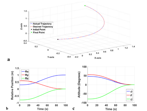
Figure 12 Simulation Results for PID; (a) Trajectory Plot (b) Relative position, (c) Relative attitude.

Figure 13 Simulation Results for PID; (a) joint angles, (b) Thrusters force,(c) Reaction Wheels control Toques, (d) Joint Torques.

LQR results

For the LQR controller, Figure 14 shows the actual trajectory tracking of the end-effector of the robotic arm. By comparing Figure 14 & 12a, it can be seen that the LQR controller was able to achieve excellent trajectory tracking like its PID counterpart. Moreover, the LQR controller was able to maintain a low fluctuation for the relative attitude, therefore, assuring a more stabilized motion. Moreover, it kept a slightly lower cyclic deviation on the manipulator’s 6th joint as illustrated in Figure 15c. Since the deviation is less than 1° MathType@MTEF@5@5@+= feaagKart1ev2aaatCvAUfeBSjuyZL2yd9gzLbvyNv2CaerbuLwBLn hiov2DGi1BTfMBaeXatLxBI9gBaerbd9wDYLwzYbItLDharqqtubsr 4rNCHbGeaGqiVyI8Vfeu0dXdh9vqqj=hEeeu0xXdbba9frpe0=GqFf ea0dXdd9vqaq=JfrVkFHe9pgea0dXdar=Jb9hs0dXdbPYxe9vr0=vr 0=vqpWqaaeaabiGaciaacaqabeaadaqaaqaaaOqaaKqzafGaaGymai adaYLHWcaSaaa@39DB@ , it can be used for more accurate operations. Going back to section 9.2.1, the LQR provided again a slightly better performance with higher stability and accuracy, however, it required more control effort (see Figure 11e), where the minimum saturation limit for operating the LQR controller was 1.5N. Moreover, the control effort generated by the reaction wheels increased by 50% with a maximum value of 1.5Nm as seen in Figure 15d & 15e.  The corresponding peak torque  produced by the joint motors is 1.5Nm, as shown in Figure 15f.
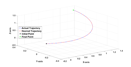
Figure 14 Trajectory Plot for the LQR.
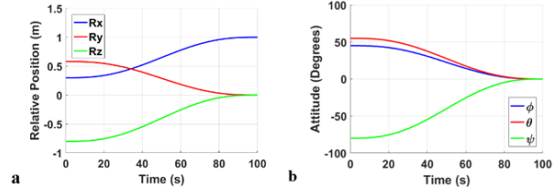
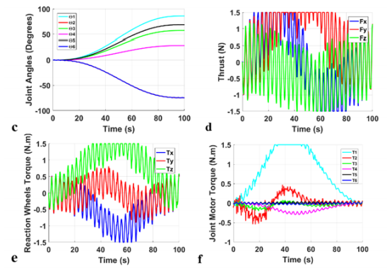
Figure 15 Simulation Results for LQR (a) relative position, (b) relative attitude, (c) joint angles, (d) Thrusters, (e) Reaction Wheels, (f) Joint Motors.

From the previous simulations, it is noticed that both PID and LQR controllers have a very similar performance. However, the LQR controller was able to offer a higher accuracy at the expense of about 50% more control effort, thus, higher fuel consumption. Therefore, depending on the mission requirements, PID or LQR could be chosen. Moreover, it should be noted that these trade-off analyses were conducted at extreme (3 orders of magnitude bigger than normal) environmental perturbations and internal disturbances. The reason for selecting such extreme values is that all previous data for the micro-gravity environment are applicable to normal spacecraft, therefore, the controllers developed for the space robot have to be robust enough to withstand the more vicious environmental and internal perturbations due to its much more complex dynamics. Table 5 shows the execution time of each individual control block.

Conclusion

Space robots are crucial for future missions that involves maintenance, repair or refueling of spacecraft, or assembly operations in space. Unlike Earth-based manipulators, the base of the space robot is not fixed in the inertial frame as a result of the dynamic coupling reactions during the motion of the manipulator. Hence, in order to develop control algorithms for such systems, it is crucial to consider the dynamic coupling effects and try to compensate for it. Moreover, the challenges facing a space robot over the fixed-based manipulators are presented, indicating the different modes of controlling a space robot and the pros and cons of each approach. Furthermore, the dynamic and kinematic modelling of a multi-DOF controlled-floating space robot in the close-range approach has been presented.

Control algorithms were developed where, feed-forward compensation was introduced to eliminate the dynamic coupling between the base-spacecraft; thus, decoupling the system into the base-spacecraft and the manipulator. Moreover, this is followed by a feed-forward linearization technique to linearize the non-linear decoupled systems, thus allowing the use of the linear LQR or PID controller as the last stage of the control algorithm. Closed loop simulations for the system were conducted, subjecting the space robot to extreme sinusoidal environmental perturbations with Gaussian random white noises, as well as parametric uncertainty due to fuel expenditure. A trade-off analysis was conducted for both controllers based on their robustness to perturbations, accuracy in trajectory tracking, fluctuations in behavior and control effort required. Results showed that the LQR controller was able to offer slightly higher trajectory tracking performance with more robustness to environmental perturbations and 30% less fluctuations in the joint angles, relative attitude and velocities; however, it required 50% more control effort. Therefore, depending on the mission requirements, the AOCS designer could choose between the slightly higher accuracy offered by the LQR controller or less fuel consumption offered by the PID controller.

As a next step, research into optimizing the path for the end-effector of the robotic arm  and the base-spacecraft, to minimize fuel consumption and achieve superior performance, is in progress. Additionally, other advanced concepts such as the kinematic and dynamic singularities along the path, applying real-time obstacle avoidance algorithms is also under development.

Acknowledgments

This research was facilitated by the University of Surrey, UK and the University of Lincoln, UK.

Conflicts of interest

Authors declare that there is no conflict of interest.

References

  1. Sweeting M. Modern small satellites-changing the economics of space. Proceedings of the IEEE. 2018;106(3):343–361.
  2. Ellery A, Kreisel J, Sommer B. The case for robotic on-orbit servicing of spacecraft: Spacecraft reliability is a myth. Acta Astronautica. 2008;63(5-6):632–648.
  3. Barbee B, Russel J, Heatwole S, et al. A Guidance and Navigation Strategy for Rendezvous and Proximity Operations with a Noncooperative Spacecraft in Geosynchronous Orbit. The Journal of the Astronautical Sciences. 2011;58(3):389–408.
  4. Xu Y, Shum H. Dynamic Control of a Space Robot System with No Thrust Jets Controlled Base. The Robotics Institute Carnegie Mellon University: Pittsburgh; 1991.
  5. Xia T, Leonard S, Deguet A, e al. Augmented Reality Environment with Virtual Fixtures for Robotic Telemanipulation in Space. IEEE/RSJ International Conference on Intelligent Robots and Systems: Vilamoura, Portugal; 2012.
  6. Shibli M. Modeling and Control of a Free-Flying Space Robot Interacting with a Target Satellite. Ph.D. dissertation, Mech Eng, Concordia University; 2005.
  7. Dubanchet V, Saussié D, Alazard D, e al. Modeling & control of a space robot for active debris removal. CEAS Space J. 2015;7:203–218.
  8. Eckersley S, Saunders C, Gooding D, e al. In-orbit assembly of largespacecraft using small spacecraft and innovative technologies. 69th International Astronautical Congress (IAC): Bremen, Germany; 2018.
  9. Papadopoulos E, Dubowsky S. On dynamic singularities in the control of free-floating manipulators. Trans ASME Dynamic Syst and Control. 1989;15:45–52.
  10. Ellery A. An engineering approach to the dynamic control of space robotic on-orbit servicers. Journal of Aerospace Engineering. 2004;218(2):79–98.
  11. Wilde M, Kwok CS, Grompone A, e al. Equations of Motion of Free-Floating Spacecraft-Manipulator Systems: An Engineer's Tutorial. Frontiers in Robotics and AI. 2018;5.
  12. Ali S, Moosavian A, Papadopoulos E. Free-flying robots in space: an overview of dynamics modeling, planning and control. Robotica. 2007;25(5):537–547.
  13. Seddaou A, Saaj C. Hα Controller for a Free-Flying Robotic Spacecraft. Proc 14th, International Symposium on Artificial Intelligence, Robotics and Automation in Space (i-SAIRAS 2018): Madrid, Spain; 2018.
  14. Vafa Z, Dubowsky S. On the dynamics of manipulators in space using the virtual manipulator approach. Proc IEEE Int Conf on Robotics and Automation: Raleigh, NC; 1987. 579–585 p.
  15. Virgili-Llop J, Zagaris C, Zappulla RI, e al. Convex optimization for proximity maneuvering of a spacecraft with a robotic manipulator. 27th AAS/AIAA Space Flight Mechanics Meeting: San Antonio, Texas; 2017.
  16. Dubowsky S, Papadopoulos E. The Kinematics, Dynamics, and Control of Free-Flying and Free-Floating Space Robotic Systems. IEEE Transactions on Robotics and Automation. 1993;9(5):531–543.
  17. Serpelloni E. Dynamics and Control of a Spacecraft-Manipulator System: Analysis, Simulation and Experiments. M.Sc. Thesis, Space Eng, Politecnico di Milano; 2011.
  18. Yoshida K. Practical Coordination Control Between Satellite Attitude and Manipulator Reaction Dynamics Based on Computed Momentum Concept. Proceedings of IEEE/RSJ International Conference on Intelligent Robots and Systems (IROS'94): Munich, Germany; 1994.
  19. Oda M. Attitude control experiments of a robot satellite. J Spacecraft and Rockets. 2000;37(6):788–793.
  20. Moradi M, Esmaelzadeh R, Ghasemi A. Adjustable adaptive fuzzy attitude control using nonlinear SISO structure of satellite dynamic. Transaction of Japan Society for Aeronautical and Space Sciences. 2012;55(5):265–273.
  21. Kulkarni J, Campbell M. An approach to magnetic Torque attitude control of satellites via H_∞ control for LTV system. 43rd IEEE Conference on Decision and Control; 2004. 273–277 p.
  22. Cheng H, Shu SL, Cheng PJ. Attitude control of a satellite using fuzzy controllers. Expert Systems with Applications. 2009;36(3):6613–6620.
  23. Singh SN, Yim W. Feedback linearization and solar pressure satellite attitude control. IEEE Transactions on Aerospace and Electronic Systems.1996;32:732–741.
  24. Almodaresi E, Bozorg M. K_p- stable regions in the space of PID controller coefficients. IET Control Theory & Applications. 2015;11(10):1642–1647.
  25. Skogestad S. Probably the best simple PID tuning rules in the world. AIChE Annual Meeting: Reno, Nevada; 2001.
  26. Ziegler JG, Nichols NB. Optimum settings for automatic controllers. J Dyn Sys Meas Control. 1993;115(2B):220–222.
  27. Åström KJ, Hägglund T. Advanced PID Control. ISA-The Instrumentation, Systems and Automation Society; 2006.
  28. Dabiri BP. Moghaddam JA, Tenreiro Machado. Optimal variable-order fractional PID controllers for dynamical systems. Journal of Computational and Applied Mathematics 2018;339:40–48.
  29. Astrom KJ, Hagglund T. Automatic tuning of PID controllers. Instrumentation Systems and Automation Society. 1985;18(15):205–210.
  30. Ezzeddin ME, Shaefi MR. Disturbance Elimination using Self-tuning PID Controller for Spinning Satellite Types. Int'l Journal of Computing, Communications & Instrumentation Engg. 2015;2(2):201–205.
  31. Morteza M. Self-tuning PID controller to three-axis stabilization of a satellite with unknown parameters. International Journal of Non-Linear Mechanics. 2013;49:50–56.
  32. You Li, Sun Zhaowei, Ye Dong. Time Efficient Robust PID Plus Controller for Satellite Attitude Stabilization Control Considering Angular Velocity and Control Torque Constraint. Journal of Aerospace Engineering. 2017;30(5).
  33. Guarnaccia L, Bevilacqua R, Pastorelli SP. Suboptimal LQR-based spacecraft full motion control: Theory and experimentation. Acta Astronautica. 2016;122:114–136.
  34. Xiaodong Liu, Yunjie Wu, Yu Zhang, e al. A control method to make LQR robust: A planes cluster approaching mode. International Journal of Control, Automation and Systems. 2014;12(2):302–308.
  35. Almeida MM, Raffo GV. Nonlinear Control of a Tiltrotor UAV for Load Transportation. 11th IFAC Symposium on Robot Control; 2015. 232–237 p.
  36. Shiau JK, Ma DM. An Autopilot Design for the Longitudinal Dynamics of a Low Speed Experimental UAV using Two Time Scale Cascade Decomposition. Transaction of the Canadian Society for Mechanical Engineering. 2009;33(3):501–521.
  37. Yang Y. Analytic LQR design for spacecraft control system based on quaternion model. Journal of Aerospace Engineering. 2012;25(3):448–453.
  38. Walker L, Spencer D. Automated proximity operations using image- based relative navigation. 26th Annual USU/AIAA Conference on Small Satellites; 2012.
  39. Vafa Z, Dubbowsky S. The kinematics and dynamics of space manipulators: The virtual manipulator approach. Int J Robotics Res. 1990;9(4):3–21.
  40. Wilde M, Kwok Choon S, Grompone A, e al. Equations of Motion of Free-Floating Spacecraft-Manipulator Systems: An Engineer’s Tutorial. Front Robot AI. 2018;5:41.
  41. Liu X, Li H, Chen Y. Dynamics and control of capture of a floating rigid body by a spacecraft robotic arm. Multibody Syst Dyn. 2015;33(3):315–332.
  42. Chen BS. A Non-Linear H∞ Control Design in Robotic Systems under parameter perturbation and external disturbance. International Journal of Control. 1994;59(2):439–461.
  43. Ross IM. Control and Optimization: An Introduction to Principles and Applications. Electronic Edition, Naval Postgraduate School: Monterey, CA; 2005.
  44. Kwakernaak H, Sivan R. Linear Optimal Control Systems. Wiley-Interscience: US; 1972.
  45. Insu Chang, Sang-Young Park, Kyu-Hong Choi. Decentralized coordinated attitude control for satellite for-mation flying via the state-dependent Riccati equation technique. International Journal of Non-Linear Mechanics. 2009;44(8):891–904.
  46. Xu J, Hu L. Formation Keeping of Micro-Satellites LQR Control Algorithms Analysis. Proceedings of 2011 International Conference on Electronics and Optoelectronics: Dalian; 2011.
  47. Fortescue P, Stark J, Swinerd G. Spacecraft Systems Engineering. John Wiley & Sons: Chichester; 2003.
  48. Fortescue P, Stark J, Swinerd G. Spacecraft Systems Engineering. John Wiley & Sons: Chichester; 2003.
  49. Parameters for calculations of kinematics and dynamics. Universal Robots; 2019.
Creative Commons Attribution License

©2020 Mohamed, et al. This is an open access article distributed under the terms of the, which permits unrestricted use, distribution, and build upon your work non-commercially.