
Research Article Volume 6 Issue 4
Finite element analysis of vibration of an isotropic thin rectangular plate subjected to different boundary conditions under point and uniformly distributed loadings
Sobamowo MG,1 
Regret for the inconvenience: we are taking measures to prevent fraudulent form submissions by extractors and page crawlers. Please type the correct Captcha word to see email ID.

Agbelusi CT,1 Oladosu SA,2 Kuku RO2
1Department of Mechanical Engineering, University of Lagos, Nigeria
2Department of Mechanical Engineering, Lagos State University, Epe Campus, Lagos, Nigeria
Correspondence: Sobamowo MG, Department of Mechanical Engineering, University of Lagos, Nigeria
Received: November 20, 2022 | Published: December 29, 2022
Citation: Sobamowo MG, Agbelusi CT, Oladosu SA, et al. Finite element analysis of vibration of an isotropic thin rectangular plate subjected to different boundary conditions under point and uniformly distributed loadings. Aeron Aero Open Access J. 2022;6(4):196-205. DOI: 10.15406/aaoaj.2022.06.00162
Download PDF
Abstract
In this paper, finite element method is applied to structural analysis of rectangular plate subjected to different boundary conditions. The governing equation of motions for the static analysis of a rectangular plate are developed using Kirchhoff plate bending theory. The verification and the reliability of the finite element methods used is established by comparing the results of an in-house MATLAB code and that of commercial computational solid mechanics code using FLEXPDE as well as exact analytical method. The results of the exact analytical method, MATLAB finite element method and FLEX finite element method show excellent agreements. Also, it was observed that the boundary conditions and the dimensions of the plate have significant influence on the vibration of plates. The results showed that Clamped- Simply Supported - Simply Supported -Simply Supported (CSSS) mixed boundary condition gave the highest deflection for each thickness and loading type while the Clamped-Clamped- Clamped -Simply Supported (CCCS) mixed boundary condition provided the lowest deflection. The FEM algorithm developed in this project shows great agreement with commercial software results. It is inferred from the study that use of the developed finite element codes in MATLAB is an easier, cheaper and quicker approach for the analysis of free vibration of an isotropic rectangular plate.
Nomenclature
a, plate length; b, plate width; E, modulus of elasticity, h, plate thickness; M, Bending moment; P, exciting load per unit area; u in-plane displacements in x-axis; v in-plane displacements in y-axis; v, Poisson’s ratio; w, plate displacement; γxy, shear strain; εx, in-plane strains in x-axis; εy, in-plane strains in y-axis; σx, normal stress in x-axis; σy, normal stress in y-axis; τxy, shear stress; ρ, density
Keywords: structural analysis, rectangular plates, boundary conditions, loading conditions, finite element analysis
Introduction
The studies on static and dynamic behaviours of plates have been presented using various methods.1 However, vibrational behaviours of complicated shapes and structures with geometry and material nonlinearity as well as nonclassical loading and boundary conditions are very difficult to be accurately described by analytical solutions. Consequently, over the years, the static and dynamic analyses of such structures have been carried out with computational methods. With the aid of meshless Galerkin method, Liew et al.,2 numerically analyzed the vibration of corrugated Reissner Mindlin plates while differential quadrature method (DQM) was used by Lu et al.,3 for natural vibration of rectangular plates. Some other researchers have also demonstrated the used of different numerical methods for the free and forced vibrations of plates under differences boundary conditions and loadings. Moon and Choi4 adopted Transfer of Dynamic Stiffness Coefficient method for vibration Analysis frame structures. Finite Element-Transfer Stiffness Coefficient Method was utilized by Choi5 for the numerical investigations of free vibration of plate structures while Wu and Lu6,7 demonstrated the use of differential cubature method to investigate the free vibration of arbitrary shaped thick plates. Tanaka et al.,8 applied boundary element method to analysis the multi-dimensional structures. Natural vibration of shear deformable general triangular plates was explored by Karunasena and Kitipornchai.9 Safaei10 analyzed the frequency-dependent damped vibrations of multifunctional foam plates. The same author investigated the effect of embedding a porous core on the free vibration behaviour of laminated composite plates.11 Kumar et al.,12 applied dynamic stiffness method to analyze the free vibration of thin functionally graded rectangular plates. Pratap et al.,13 presented vibration analysis of a thin functionally graded plate having an out of plane material inhomogeneity resting on Winkler-Pasternak foundation subjected to different boundary conditions. Ramu and Mohanty14 studied the natural vibration analysis of rectangular plate structures using finite element method. Liu et al.,15 presented a unified modeling method for vibration analysis of reinforced functionally graded plate resting on elastic foundation with elastic boundary conditions. Fattahi and Safaei16 used different nonlocal plate models to study free vibration of graphene sheets in an elastic matrix. Gholami and Ansari17 explored the nonlinear stability and vibration of pre/post-buckled multilayer functionally graded rectangular plates. In author’s works,18–20 the same author presented nonlinear vibration of functionally graded graphene platelet-reinforced composite rectangular plates. In this work, finite element method is applied to structural analysis of rectangular plate subjected to different boundary conditions under point and uniformly distribution loads. The governing equation of motions for the static analysis of a rectangular plate are developed using Kirchhoff plate bending theory. The verification and the reliability of the finite element methods used is established by comparing the results of an in-house MATLAB code and that of commercial computational solid mechanics code using FLEXPDE as well as exact analytical method.
Model development
Considering a rectangular plate having thickness, mass density as illustrated in Figure 1. It is assumed that the plate is linearly elastic and the effects of shear deformation as well as that of rotary inertia are neglected. Moreover, the development of the vibration model is based on the Kirchhoff plate bending theory From the basic theory of stress-stress and displacement analysis, the in-plane displacements u (in x-axis) and v (in y-axis) can be expressed as
(1)
(2)
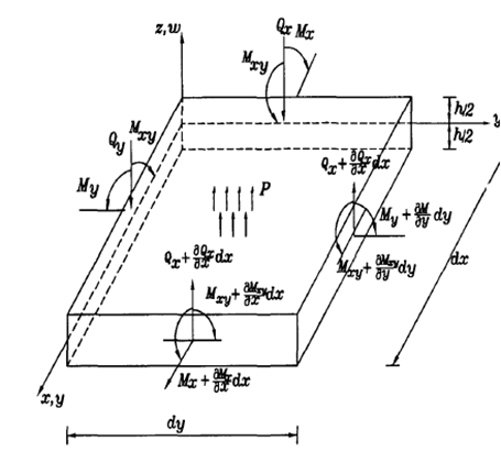
Figure 1 Free body diagram rectangular plate.
Since the transverse shear deformation is not considered, we can write the in-plane strains as
(3)
(4)
(5)
Assuming the plane stress condition for the plate, the constitutive equations for the stresses are given
(6)
(7)
(8)
Also, the moments as shown in Figure 1 are defined as
(9)
(10)
(11)
On substitution Eq. (6), (7) and (8) into Eqs. (9), (10) and (11), we have
(12)
(13)
(14)
Evaluation of Eqs. (12), (13) and (14) gives
(15)
(16)
(17)
From the free body diagram in Figure 1, we can obtain the equilibrium equation. The moment equilibrium about y- and x-axes and force equilibrium about z-axes yield after neglecting higher order terms
(18)
(19)
For a classical plate, the shear forces along x- and y-axes are related to the distributed pressure loading as
(20)
Differentiating Eqs. (18) and (19) with respect to x and y, respectively, we have
(21)
(22)
Adding Eqs. (21) and (22), we have
(23)
From Eq. (20)
(24)
Substitute Eq. (24) into Eq. (23), we have
(25)
Eq. (3.25) can be written as
(26)
Now, we can substitute Eqs. (3.15), (3.16) and (3.17) into Eq. (3.26),
(27)
Evaluation of the above Eq. (27), provides
(28)
For a plate made of homogenous and isotropic material where Dx = Dy = Dz, we have
(29)
where
Therefore, Eq. (29) can be written as
(30)
The expression
refers to the flexural rigidity of the plate. On denoting
, we have
(31)
The equation of motion for a plate made of homogenous and isotropic material is
(32)
For free vibration, we have
(33)
Alternatively, we can write
(34)
where the bi-harmonic operator
(35)
In the above equations, is the exciting load per unit area,
and
are the modulus of elasticity, plate thickness, the Poisson’s ratio, and density, respectively.
The boundary conditions for the static vibration are given
- Clamped-Clamped-Clamped-Simply Supported
(36)
- Clamped-Simply Supported-Clamped-Simply supported
(37)
- Clamped-Clamped-Simply Supported-Simply Supported
(38)
- Clamped-Simply Supported-Simply-Simply Supported
(39)
(Figures 2–5)
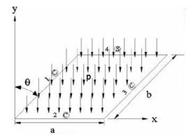
Figure 2 Clamped-clamped-clamped-simply supported (CCCS) under loading conditions.

Figure 3 Clamped-simply supported-clamped-simply supported (CSCS) under loading conditions.
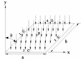
Figure 4 Clamped-clamped-simply supported- supported-simply supported (CCSS) under loading conditions.
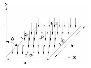
Figure 5 Clamped-simply supported-simply supported--supported-simply supported (CSSS) under loading conditions.
Finite element analysis to static analysis of rectangular plates
The approximate trial function for the fourth-order partial differential equation is given as
(40)
where the parametric trial function is taken as
(41)
The Galerkin weighted residual equation is given by.
(42)
After the weak formulation, we have
(43)
Which can be written in matrix form as
(44)
the local stiffness matrix
(45)
and the local load matrix
(46)
Finite element solutions to the natural frequencies of the rectangular plates under different boundary conditions
From the governing equation in previous section, the finite element solution of the natural frequency of the rectangular plate can be expressed as
(48)
Which can be well written as
(49)
If we substitute Eq. (42), we have
(50)
Substituting the shape function in Eq. (41) and carrying out the integration, we have
- Clamped-clamped-clamped-simply supported
(51)
- Clamped-simply supported-clamped-simply supported
(52)
- Clamped-clamped-simply supported-simply supported
(53)
- Clamped-simply supported-simply-simply supported
(54)
- Clamped- clamped-clamped-clamped-supported
(55)
- Simply supported -simply supported-simply-simply supported
(56)
For the sake of comparison of results, exact analytical solutions for the plate under different boundary conditions are developed. For example, for the Simply Supported -Simply Supported-Simply-Simply Supported plate with point load is given as
(57)
The exact analytical solution for the natural frequency is given as
(58)
Parameter used for simulations
Case 1:
Plate dimension: 1m x 1m
Plate thickness: 0.025 m, 0.05 m and 0.075 m
Point load: 4500 N
Uniformly distributed load = 4.5 kN/m
The mechanical properties of the plate were E= 205GPa and ρ= 8050 kg/m3. The Poisson’s ratio is 0.3 as shown in Table 1a.
|
Material
|
Density kg/m3
|
Yield stress (Mpa)
|
Young's modulus (N/m2)
|
Poisson's ratio
|
|
Steel
|
8050
|
250
|
205x109
|
0.3
|
|
Table 1a Physical properties of the materials used for the simulationsp
Case 2:
Plate dimension: 700 mm x 700 mm
Plate thickness: 10 mm
Point load: 800 N
The mechanical properties of the plate were E= 205GPa and ρ= 8050 kg/m3. The Poisson’s ratio is 0.3 as shown in Table 1b.
|
Material
|
Density kg/m3
|
Yield stress (Mpa)
|
Young's modulus (N/m2)
|
Poisson's ratio
|
|
|
Aluminium
|
2700
|
276
|
70x109
|
0.3
|
|
Table 1b Physical properties of the materials used for the simulations
Result and discussion
The results of the numerical simulations using MATLAB and FlexPDE are presented in this section. Grid independence and sensitivity analyses are carried out. Figures 6–8 present the finite element discretization of the plate.
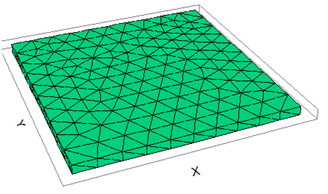
Figure 6 Discretisation of 1 m by 1 m Mild steel plate.
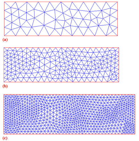
Figure 7 Triangular element mesh and refined mesh (MATLAB) for a rectangular plate of length = 500 mm, width = 200 mm and thickness = 12 mm.
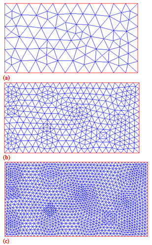
Figure 8 Triangular element mesh and refined mesh (MATLAB) for a rectangular plate of length = 500 mm, width = 300 mm and thickness = 12 mm.
Grid independency test and code verification
A mesh sensitivity analysis was carried out to ensure grid independence. In order to choose the grid size, grid independency test is performed for different grid mesh of sizes. The number of grid size from which there is no appreciable change in the results and the accuracy is not affected even if the numbers of elements are increased by decreasing the size of the elements.
In order to verify and establish the reliability of the finite element methods used in this work, we made some comparisons of the results of an in-house MATLAB code and that of commercial computational solid mechanics code using FLEXPDE as well as exact analytical method. It is established that, the two finite element methods have been proven to be adequate and give accurate results for vibration problem presented in this project. The results show excellent agreement between the exact solution and the finite element solution.
Clamped-clamped-clamped-simply supported (CCCS) plate subjected to point load
Table 2 shows the effect of plate thickness on the deflection of the plate for the Clamped-Clamped-Clamped-Simply Supported (CCCS) boundary conditions subjected to point load of 4.5kN.
|
|
Maximum deflection of the plate (m)
|
|
|
S. No. Thickness
|
Exact analytical solution
|
FEM MATLAB
|
FEM FLEXPDE
|
|
1 0.025
|
4.19×10⁻²
|
4.86×10⁻²
|
5.45×10⁻²
|
|
2 0.050
|
6.58×10⁻³
|
7.45×10⁻³
|
7.93×10⁻³
|
|
3 0.075
|
2.23×10⁻³
|
3.04×10⁻³
|
2.79×10⁻³
|
Table 2 Comparison of the deflection results for plate of length = 1 m, width = 1 m and Point load = 4500 N
Clamped-clamped-clamped-simply supported (CCCS) plate subjected to uniformly distributed load
While Table 3 shows the effect of plate thickness on the deflection of the plate for the same boundary conditions subjected to a uniformly distributed load of 4.5kN/m.
|
|
Maximum deflection of the plate (m)
|
|
|
S. No. Thickness
|
Exact analytical solution
|
FEM MATLAB
|
FEM FLEXPDE
|
|
1 0.025
|
5.65×10⁻³
|
5.86×10⁻³
|
5.79×10⁻³
|
|
2 0.050
|
7.98×10⁻⁴
|
8.45×10⁻⁴
|
8.20×10⁻⁴
|
|
3 0.075
|
2.53×10⁻⁴
|
3.04×10⁻⁴
|
2.79×10⁻⁴
|
Table 3 Comparison of the deflection results for plate of length = 1 m, width = 1 m and uniformly distributed load = 4.5kN/m2
The results obtained for deflections from FLEXPDE give good agreement with the results obtained from FEM MATLAB with the FLEXPDE values slightly higher. However, the difference between the two values reduces from at thickness of the plate increases. Also, it was observed that the deflection of the plate decreases with increase in the thickness of the plate. This is because no shear deformation is considered in the analysis of thin plate. If the plate is thick the effect of shear deformation becomes significant and therefore the result obtained may vary. Therefore, to reduce deflection, the thickness of the plate should be increased.
Clamped-simply supported-clamped-simply supported (CSCS) plate subjected to point load
Table 4 shows the effect of plate thickness on the deflection of the plate for the Clamped- Clamped-Simply Supported -Clamped-Simply Supported (CSCS) boundary conditions subjected to point load of 4.5kN.
|
|
Maximum deflection of the plate (m)
|
|
|
S. No. Thickness
|
Exact analytical solution
|
FEM MATLAB
|
FEM FLEXPDE
|
|
1 0.025
|
5.23×10⁻²
|
6.17×10⁻²
|
5.45×10⁻²
|
|
2 0.050
|
7.34×10⁻³
|
8.23×10⁻³
|
8.52×10⁻³
|
|
3 0.075
|
2.51×10⁻³
|
2.78×10⁻³
|
2.83×10⁻³
|
Table 4 Comparison of the deflection results for plate of length = 1 m, width = 1 m and Point load = 4500 N
Clamped-simply supported-clamped-simply supported (CSCS) plate subjected to uniformly distributed load
While Table 5 shows the effect of plate thickness on the deflection of the plate for the same boundary conditions subjected to a uniformly distributed load of 4.5kN/m.
|
|
Maximum deflection of the plate (m)
|
|
|
S. No. Thickness
|
Exact analytical solution
|
FEM MATLAB
|
FEM FLEXPDE
|
|
1 0.025
|
7.65×10⁻³
|
7.55×10⁻³
|
8.69×10⁻³
|
|
2 0.050
|
1.22×10⁻³
|
1.12×10⁻³
|
1.15×10⁻³
|
|
3 0.075
|
3.46×10⁻⁴
|
3.44×10⁻⁴
|
3.56×10⁻⁴
|
Table 5 Comparison of the deflection results for plate of length = 1 m, width = 1 m and uniformly distributed load = 5kN/m2
The results obtained for deflections from FLEXPDE give good agreement with the results obtained from FEM MATLAB with the FLEXPDE values slightly higher. However, the difference between the two values reduces from at thickness of the plate increases. Also, it was observed that the deflection values reduce with increase in thickness.
Clamped -clamped- simply supported -simply supported (CCSS) plate subjected to point load
Table 6 shows the effect of plate thickness on the deflection of the plate for the Clamped- Clamped-Clamped-Simply Supported-Simply Supported (CCSS) boundary conditions subjected to point load of 4.5kN.
|
|
Maximum deflection of the plate (m)
|
|
|
S. No. Thickness
|
Exact analytical solution
|
FEM MATLAB
|
FEM FLEXPDE
|
|
1 0.025
|
5.67×10⁻²
|
6.17×10⁻²
|
5.45×10⁻²
|
|
2 0.050
|
8.47×10⁻³
|
8.51×10⁻³
|
8.58×10⁻³
|
|
3 0.075
|
2.71×10⁻³
|
2.82×10⁻³
|
2.86×10⁻³
|
Table 6 Comparison of the deflection results for plate of length = 1 m, width = 1 m and Point load = 4500 N
Clamped -clamped-simply supported -simply supported (CCSS) plate subjected to uniformly distributed load
While Table 7 shows the effect of plate thickness on the deflection of the plate for the same boundary conditions subjected to a uniformly distributed load of 4.5kN/m.
|
|
Maximum deflection of the plate (m)
|
|
|
S. No. Thickness
|
Exact analytical solution
|
FEM MATLAB
|
FEM FLEXPDE
|
|
1 0.025
|
8.27×10⁻³
|
9.55×10⁻³
|
9.71×10⁻³
|
|
2 0.050
|
1.15×10⁻³
|
1.24×10⁻³
|
1.26×10⁻³
|
|
3 0.075
|
3.52×10⁻⁴
|
3.61×10⁻⁴
|
3.70×10⁻⁴
|
Table 7 Comparison of the deflection results for plate of length = 1 m, width = 1 m and uniformly distributed load = 5kN/m2
The results obtained for deflections from FLEXPDE give good agreement with the results obtained from FEM MATLAB with the FLEXPDE values slightly higher. However, the difference between the two values reduces from at thickness of the plate increases. Also, it was observed that the deflection values reduce with increase in thickness.
Clamped -simply supported- simply supported -simply supported (CSSS) plate subjected to point load
Tables 8 shows the effect of plate thickness on the deflection of the plate for the Clamped -Simply Supported-Simply Supported -Simply Supported (CCSS) boundary conditions subjected to point load of 4.5kN.
|
|
Maximum deflection of the plate (m)
|
|
|
S. No. Thickness
|
Exact analytical solution
|
FEM MATLAB
|
FEM FLEXPDE
|
|
1 0.025
|
7.25×10⁻²
|
6.89×10⁻²
|
6.85×10⁻²
|
|
2 0.050
|
1.02×10⁻²
|
9.47×10⁻³
|
9.49×10⁻³
|
|
3 0.075
|
3.15×10⁻³
|
3.13×10⁻³
|
3.14×10⁻³
|
Table 8 Comparison of the deflection results for plate of length = 1 m, width = 1 m and Point load = 4500 N
Clamped -simply supported- simply supported -simply supported (CSSS) plate subjected to uniformly distributed load
While Table 9 shows the effect of plate thickness on the deflection of the plate for the same boundary conditions subjected to a uniformly distributed load of 4.5kN/m.
|
|
Maximum deflection of the plate (m)
|
|
|
S. No. Thickness
|
Exact analytical solution
|
FEM MATLAB
|
FEM FLEXPDE
|
|
1 0.025
|
1.07×10⁻²
|
1.15×10⁻³
|
1.15×10⁻³
|
|
2 0.050
|
1.45×10⁻³
|
1.50×10⁻³
|
1.50×10⁻³
|
|
3 0.075
|
4.31×10⁻⁴
|
4.71×10⁻⁴
|
4.70×10⁻⁴
|
Table 9 Comparison of the deflection results for plate of length = 1 m, width = 1 m and uniformly distributed load = 5kN/m2
The results obtained for deflections from FLEXPDE give good agreement with the results obtained from FEM MATLAB with the FLEXPDE values slightly higher. However, the difference between the two values reduces from at thickness of the plate increases. Also, it was observed that the deflection values reduce with increase in thickness.
Figures 9&10 shows the effects of plate thickness and boundary conditions on the deflection of the plate under point load. While Figures 11–16 presents the impacts of the plate thickness and boundary conditions on the deflection of the plate under uniformly distributed load. The figures show that the deflection of the plate decreases as the thickness of the plate increases. However, the higher the number of simply supported boundaries, the higher the deflection of the plate. This also connotes that the higher the number of clamped-supported boundaries, the lower the deflection of the plate. Figures 17–21 shows the three-dimensional view of the vibration of the plate using FLEXPDE.
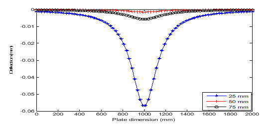
Figure 9 Deflection versus dimension plot of point distributed load under CCCS boundary conditions.
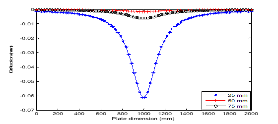
Figure 10 Deflection versus dimension plot of point distributed load under CSCS boundary conditions.
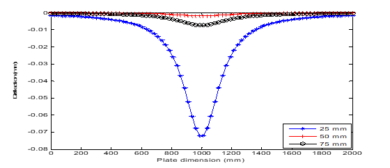
Figure 11 Deflection versus dimension plot of uniformly distributed load under CCSS boundary conditions.
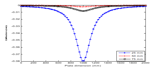
Figure 12 Deflection versus dimension plot of uniformly distributed load under CSSS boundary conditions.
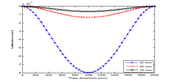
Figure 13 Deflection versus dimension plot of uniformly distributed load under CCCS boundary conditions.
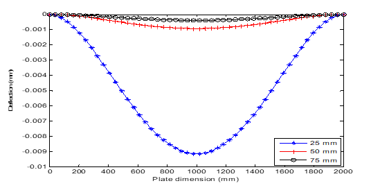
Figure 14 Deflection versus dimension plot of uniformly distributed load under CSCS boundary conditions.
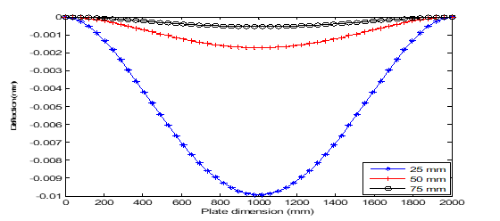
Figure 15 Deflection versus dimension plot of uniformly distributed load under CCSS boundary conditions.
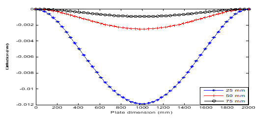
Figure 16 Deflection versus dimension plot of uniformly distributed load under CSSS boundary conditions.
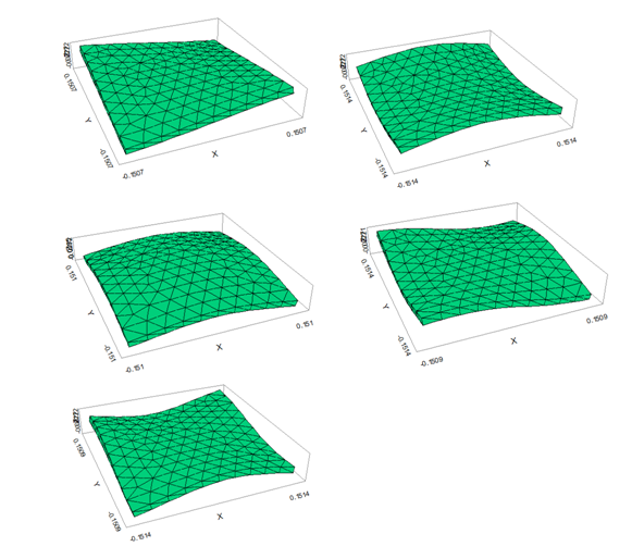
Figure 17 Different modes of vibration (FLEXPDE FEM) for a rectangular plate of length = 1000 mm, width = 1000 mm and thickness = 75 mm.

Figure 18 Different modes of vibration (FLEXPDE FEM) for a rectangular plate of length = 200 mm, width = 100 mm and thickness = 12 mm.
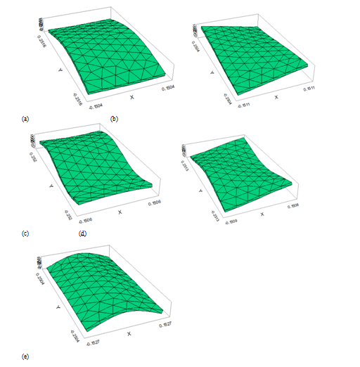
Figure 19 Different modes of vibration (FLEXPDE FEM) for a rectangular plate of length = 500 mm, width = 100 mm and thickness = 12 mm.

Figure 20 Different modes of vibration (FLEXPDE FEM) for a rectangular plate of length = 500 mm, width = 100 mm and thickness = 12 mm.
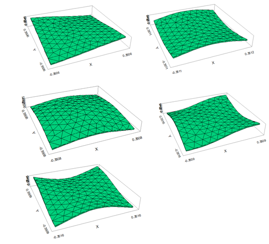
Figure 21 Different modes of vibration (FLEXPDE FEM) for a rectangular plate of length = 700 mm, width = 700 mm and thickness = 10 mm.
The natural frequencies of plates are investigated versus modal numbers by varying the length and width of the plates with clamped-clamped-clamped - simply supported (CCCS), clamped-simply-clamped - simply supported (CSCS), clamped-clamped-simply - simply supported (CCSS), clamped-simply-simply- simply supported (CSSS) boundary conditions as presented in Table 10. The frequencies of the plates increase by increasing the modal number, and CCCS frequencies are greater than the frequencies of other boundary conditions. It is observed from the Table that the boundary conditions have a significant influence on the vibration of plates. Also, the obtained results clearly show that frequency parameters increase if more constraints are included. Simply supported at all edges have lower frequency than clamped edge due to clamping in all edges. This means that as the constraint on the edges increases the flexural rigidity of the plate increases and hence there is an increase in the frequency. Table 11 presents comparison of results of the first 6 natural frequencies and mode shapes of simply supported rectangular plates.
|
Modes
|
CCCS
|
CSCS
|
CCSS
|
CSSS
|
|
(1, 1)
|
54.34
|
38.45
|
41.84
|
10.56
|
|
(1, 2)
|
55.13
|
40.11
|
42.48
|
15.98
|
|
(2, 2)
|
56.06
|
42.97
|
44.25
|
27.53
|
|
(1, 3)
|
64.98
|
53.65
|
55.31
|
32.87
|
|
(2, 3)
|
68.75
|
57.85
|
59.02
|
39.21
|
|
(1, 4)
|
75.27
|
67.33
|
69.18
|
48.9
|
|
(3, 3)
|
82.81
|
74.72
|
76.89
|
57.42
|
Table 10 Effects of boundary conditions on the natural frequencies at different mode numbers
|
Mode number
|
6.25 mm
|
12.5 mm
|
25 mm
|
50 mm
|
|
1
|
136.9
|
272.2
|
535.3
|
1024
|
|
2
|
263.3
|
522.27
|
1019.8
|
1906.8
|
|
3
|
422.3
|
833.6
|
1634.9
|
3008.8
|
|
4
|
474.5
|
940.3
|
1823.1
|
3100.6
|
|
5
|
547.9
|
1083.3
|
2088.3
|
3316
|
|
6
|
758.1
|
1493.7
|
2847.7
|
3748.1
|
Table 11 Effects of plate thickness conditions on the natural frequencies at different mode numbers (SSSS)
The table shows that the results of the natural frequency in this work agree very well with the results of the natural frequencies of the exact analytical solution and those numerical solutions available in literature and with exact solutions. Also, it was established that accuracy in the finite element solution increases as the thickness of the rectangular plate increases.
Conclusion
In this work, finite element method is applied to structural analysis of rectangular plate subjected to different boundary conditions. The verification and the reliability of the finite element methods used in this work have been established by comparing the results of an in-house MATLAB code and that of commercial computational solid mechanics code using FLEXPDE as well as exact analytical method. The results of the exact analytical method, MATLAB finite element method and FLEX finite element method show excellent agreements. Also, it was observed that the boundary conditions and the dimensions of the plate have significant influence on the vibration of plates. The results showed that Clamped- Simply Supported - Simply Supported -Simply Supported (CSSS) mixed boundary condition gave the highest deflection for each thickness and loading type while the Clamped-Clamped- Clamped-Simply Supported (CCCS) mixed boundary condition provided the lowest deflection. The FEM algorithm developed in this project shows great agreement with commercial software results and can be used by any person who has the MATLAB code. Although, the processing time for MATLAB symbolic language is higher than if one uses numbers in the equations. However, the authors believe that using the first strategy is better for code learning as the code consists of a good way to learn the finite element method in its state-of-art. It could be inferred from the study that use of the developed finite element codes in MATLAB is an easier, cheaper and quicker approach for the analysis of free vibration of a thin isotropic rectangular plate.
Acknowledgments
We thank University of Lagos, Nigeria and Lagos State University, Nigeria for providing us conducive environment and essential materials to carry out this research.
Conflicts of interest
The authors declare that there are no conflicts of interest.
Funding
References
- Karunasena W, Kitipornchai S. Free vibrations of shear deformable general triangular plates. J Sound Vibration. 1997;199(5):595–613.
- Liew KM, Peng LX, Kitipornchai S. Vibration analysis of corrugated Reissner Mindlin plates using a mesh-free Galerkin method. Int J Mech Sci. 2009;51(9,10):642–652.
- Lu CF, Zhang ZC, Chen WQ. Free vibration of generally supported rectangular Kirchhoff plates: State-space-based differential quadrature method. Int J Numer Meth Engng. 2007;70:1430–1450.
- Moon DH, Choi MS. Vibration Analysis for Frame Structures Using Transfer of Dynamic Stiffness Coefficient. J Sound Vibration. 2000;234(5):725–736.
- Myung Soo Choi. Free Vibration Analysis of Plate Structures Using Finite Element-Transfer Stiffness Coefficient Method. KSME Int J. 2003;17(6):805–815.
- Petyt M. Introduction to Finite Element Vibration Analysis. Cambridge University, New York; 1990.
- Wu L, Liu J. Free vibration analysis of arbitrary shaped thick plates by differential cubature method. Int J Mech Sci. 2005;47:638.
- Tanaka M, Yamagiwa K, Miyazaki K, et al. Free vibration analysis of elastic plate structures by boundary element method. Eng Analysis. 1988;5(4):182–188.
- Karunasena W, Kitipornchai S. Free vibrations of shear deformable general triangular plates. J Sound Vibration. 1997;199(5):595613.
- Safaei B. Frequency-dependent damped vibrations of multifunctional foam plates sandwiched and integrated by composite faces. Euro Phys J Plus. 2021;136(6):646.
- Safaei B. The effect of embedding a porous core on the free vibration behaviour of laminated composite plates. Steel Comp Struct. 2020;35(5):659–670.
- Kumar S, Vinayak Ranjan, Jana P. Free vibration analysis of thin functionally graded rectangular plates using the dynamic stiffness method. Comp Struct. 2018;197:39–53.
- Pratap Singh P, Azam MS, Ranjan Vinayak. Vibration analysis of a thin functionally graded plate having an out of plane material inhomogeneity resting on Winkler-Pasternak foundation under different combinations of boundary conditions. Proceedings of the Institution of Mechanical Engineers, Part C: Journal of Mechanical Engineering Science. 2018.
- Ramu I, Mohanty SC. Study on free vibration analysis of rectangular plate structures using finite element method. Procedia Engineering. 2012;38:2758–2766.
- Liu JC, Deng XW, Wang QS, et al. A unified modeling method for dynamic analysis of GPL-reinforced FGP plate resting on Winkler-Pasternak foundation with elastic boundary conditions. Comp Struct. 2020;244:112217.
- Fattahi AM, Safaei B. Free vibrational response of single-layered graphene sheets embedded in an elastic matrix using different nonlocal plate models. Mechanics. 2017;23(5):678–687.
- Gholami R, Ansari R. Nonlinear stability and vibration of pre/post-buckled multilayer FG-GPLRPC rectangular plates. App Math Model. 2019;65:627–660.
- Gholami R, Ansari R. Nonlinear harmonically excited vibration of third-order shear deformable functionally graded graphene platelet-reinforced composite rectangular plates. Eng Struct. 2018;156:197–209.
- Gholami R, Ansari R. Asymmetric nonlinear bending analysis of polymeric composite annular plates reinforced with graphene nano platelets. Int J Multi Comp Engg. 2017;17(1):45–63.
- Gholami R, Ansari R. On the nonlinear vibrations of polymer nano composite rectangular plates reinforced by graphene nano platelets: A unified higher-order shear deformable model. Iran J Sci Tech Tran Mech Engg. 2019;43(1):603–620.

©2022 Sobamowo, et al. This is an open access article distributed under the terms of the,
which
permits unrestricted use, distribution, and build upon your work non-commercially.


