
Research Article Volume 2 Issue 5
Finite element analysis of flow and heat transfer of dissipative Casson-Carreau nanofluid over a stretching sheet embedded in a porous medium
MG Sobamowo,
Regret for the inconvenience: we are taking measures to prevent fraudulent form submissions by extractors and page crawlers. Please type the correct Captcha word to see email ID.

AA Yinusa, AA Oluwo, SI Alozie
Department of Mechanical Engineering, University of Lagos, Nigeria
Correspondence: MG Sobamowo, Department of Mechanical Engineering, University of Lagos, Akoka, Lagos, Nigeria, Tel 2347034717417
Received: September 18, 2018 | Published: October 8, 2018
Citation: Sobamowo MG, Yinusa AA, OluwoAA, et al. Finite element analysis of flow and heat transfer of dissipative Casson-Carreau nanofluid over a stretching sheet embedded in a porous medium. Aeron Aero Open Access J. 2018;2(5):294-308. DOI: 10.15406/aaoaj.2018.02.00064
Download PDF
Abstract
In this paper, combined influences of thermal radiation, inclined magnetic field and temperature-dependent internal heat generation on unsteady two-dimensional flow and heat transfer analysis of dissipative Casson-Carreau nanofluid over a stretching sheet embedded in a porous medium is investigated. Similarity transformations are used to reduce the developed systems of governing partial differential equations to nonlinear third and second orders ordinary differential equations which are solved using finite element method. In the study, kerosene is used as the base fluid which is embedded with the silver (Ag) and copper (Cu) nanoparticles. Also, effects of other pertinent parameters on the flow and heat transfer characteristics of the Casson-Carreau nanofluids are investigated and discussed. From the results, it is established temperature field and the thermal boundary layers of Ag-Kerosene nanofluid are highly effective when compared with the Cu-Kerosene nanofluid. Heat transfer rate is enhanced by increasing in power-law index and unsteadiness parameter. Skin friction coefficient and local Nusselt number can be reduced by magnetic field parameter and they can be enhanced by increasing the aligned angle. Friction factor is depreciated and the rate of heat transfer increases by increasing the Weissenberg number. A very good agreement is established between the results of the present study and the previous results. The results of present analysis can help in expanding the understanding of the thermo-fluidic behaviour of the Casson-Carreau nanofluid over a stretching sheet as applied in manufacturing industries and production engineering.
Keywords: MHD, nanofluid, non-uniform heat source/sink, Carreau fluid, thermal radiation and free convection, finite element method
Introduction
The recent studies in the past few decades have shown that the study of Non-Newtonian have attracted tremendous attractions in the study of fluid dynamics. The flow applications of non-Newtonian fluids are evident in polymer devolatization and processing, wire and fiber coating, heat exchangers, extrusion process, chemical processing equipment, etc. Also, combining heat transfer with the concept of stretching flow is vital in the afore-mentioned areas of applications. Such processes have great affinity for cooling rates and stretching simultaneously.1 Consequently, in the past few years, research efforts have been directed towards the analysis of this very important phenomenon of wide areas of applications. Moreover, the promising significance of magnetohydrodynamics (MHD) fluid behavior in concerned applications such as in blood flow still provokes the continuous studies and interests of researchers. Additionally, the incorporation of radiation through thermal analysis is vital in technology involving solar energy, space vehicles, systems with propulsion, plasma physics in the flow structure of atomic plants, combustion processes, internal combustion engines, ship compressors, solar radiations and in chemical processes and space ship with high temperature level re-entry aerodynamics. Furthermore, there are various engineering and industrial applications of magnetohydrodynamics (MHD) fluid behavior such as in the study of the growth of crystals, blood flow etc. Therefore, the influences of external factors such as thermal radiation and magnetic field on the thermofluid problem concerning Newtonian and Non-Newtonian fluid have been widely analyzed in recent times.
In an early study, MHD fluid flow over a surface that is susceptible to stretching was critically studied by Anderson et al.2,3 In their studies, effect of transient variables on the film size2 and magnetic influence on the fluid flow characteristics were explored numerically.3 Few years later, Chen4 investigated the fluid film that obeys power-law flow of unsteady thermal-stretching sheet while Dandapat5,6 focused on the effect of changing viscosity as well as thermo-capillarity on the heat transfer rate of film flow over a sheet susceptible to stretching. Meanwhile, Wang7 developed an analytical or close form solution for momentum and energy (heat transfer) of film flow over a surface susceptible to stretching. Also, Chen8 and Sajid et al.9 investigated the motion characteristics involving non-Newtonian thin film over a transient stretching surface considering viscous dissipation using HAM and HPM. After a year, Dandapat et al.,10 presented the analysis using a two-dimensional flow over a transient sheet that is capable of stretching while in the same year, impact of power-law index was carried out by Abbasbandy et al.11 Santra & Dandapat12 numerically investigated the same considering a transient horizontal elongating sheet. A numerical approach was also used by Sajid et al.13 to analyze the micropolar film flow over an inclined plate, moving belt and vertical cylinder. A year later, Noor & Hashim14 investigated the influence of magnetic parameter and thermocapillarity on an unsteady liquid film flow over similar sheet while Dandapat & Chakraborty15 and Dandapat & Singh16 presented the thin film flow analysis over a non-linear stretching surface with the effect of transverse magnetic field. Heat transfer characteristics of the thin film flows considering the different channels have also been analyzed by Abdel-Rahman,17 Khan et al.18 Liu et al.19 and Vajaravelu et al.20 Meanwhile, Liu & Megahad21 used HPM to analyze the thermofluidic effect of thin film with internal heat generation and changing heat flux while Seddeek as well as other recent works22-35 investigated the impacts of thermal radiation and changing viscosity on magnetohydrodynamics in unforced convection fluid flow over a flat plate that is semi-infinite.
Other researchers went on to present their view on the interesting topic by adapting nanofluid into the generic three dimensional fluid model with radiation effect.36-48 Makinde & Animasaun49 investigated the effect of cross diffusion on MHD bioconvection flow over a horizontal surface. In another study, Makinde & Animasaun50 presented the MHD nanofluid on bioconvection flow of a paraboloid revolution with nonlinear thermal radiation and chemical reaction while Sandeep,51 Reddy et al.52 and Ali et al.53 studied the heat transfer behaviour of MHD flows. Maity et al.54 analyzed thermocapillary flow of a thin Nanoliquid film over an unsteady stretching sheet. Furthermore, different studies on the flow and heat transfer behaviour as well as entropy generation for different non-Newtonian fluids under difference internal and external conditions.55-72 The above reviewed studies have been the consequent of the various industrial and engineering applications of non-Newtonian fluids. Among the classes of non-Newtonian fluids, Carreau fluid which its rheological expressions were first introduced by Carreau,73 is one of the non-Newtonian fluids that its model is substantial for gooey, high and low shear rates.74 On account of this headway, it has profited in numerous innovative and assembling streams.74-87 Owing to these applications, different studies have been carried out to explore the characteristics of Carreau liquid in flow under different conditions. Kumar et al.40 applied numerical scheme to analyze the thermofluidic behaviour of a liquid film capable of conducting electricity. The fluid is based on the structure of liquid phase and interactive behaviour of solid of a two-phase suspension. It is able to capture complex rheological properties of a fluid, unlike other simplified models like the power law88 and second, third or fourth-grade models.89,90
Casson fluids are Jelly, honey, protein, Human blood and fruit juices. Concentrated fluids like sauces, honey, juices, blood, and printing inks can be well described using this model. The effect of magnetohydrodynamic Casson fluid flow on a laterally positioned elongating sheet was explained by Nadeem et al.91 The review studies have been analyzed using approximate analytical, semi-analytical and numerical methods. Among the numerical methods, the numerical solutions of FEM represent efficient ways of obtaining solutions to nonlinear problems even with complexities in the boundary conditions and geometries.92-94 Therefore, using FEM, this work presents numerical investigations of the combined influences of thermal radiation, inclined magnetic field and internal heat generation that is temperature-dependent on unsteady two-dimensional flow and heat transfer analysis of dissipative Casson-Carreau nanofluid over a stretching sheet embedded in a porous medium. Using kerosene as the base fluid embedded with the silver (Ag) and copper (Cu) nanoparticles, the effects of other pertinent parameters on flow and heat transfer characteristics of the nanofluids are investigated and discussed. The analysis of the stretched flows with heat transfer is very significant in controlling the qualities of the end products in manufacturing and metal forming processes. Such processes have great dependences on the stretching and cooling rates. The results of present analysis can help in expanding the understanding of the thermo-fluidic behaviour of the Casson-Carreau nanofluid over a stretching sheet as applied in manufacturing industries and production engineering.
Problem formulation
From the transient, two-dimensional boundary layer fluid flow of a conducting and heat generating Casson and Carreau nanofluids over a sheet susceptible to stretching extreme by liquid film of uniform size (thickness) h(t) as represented schematically in Figure 1. The stretching velocity along x-axis is U(x,t) and y–axis is perpendicular to it with dissipation and volume fraction considered.
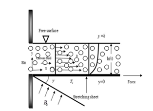
Figure 1 Flow geometry of the problem.
Using [85],
(1)
or
(2)
Also employing the tensor given as95
(3)
is the extra tensor, ηo is the zero shear rate viscosity, Γ is the time constant, n is the power-law index and
is defined as
where
is the second invariant strain tensor.
Following the assumptions, the equations for continuity and motion for the flow analysis of Carreau and Casson fluids are
(4)
(5)
(6)
where
(7a)
(7b)
(7c)
(8)
(9)
(using Roseland’s approximation) (10)
Assuming no slip condition, the appropriate boundary conditions are given as
(11a)
(11b)
It should be stated at this juncture that the formulated mathematical model is implicitly in the domain x≥0. In other to annul discontinuities as a result of surface effects, a further assumption of smooth surface is made. Likewise, the effect of shear due to the interfacial quiescent atmosphere i.e. is removed. The shear stress based on the Newton’s law of viscosity
as well as the heat flux
disappear when the adiabatic free surface condition is considered (at y=h).
It should be noted that
(12)
The above boundary conditions are in line with the works of Kumar et al.,56 and Abel et al.,76
The non-uniform heat generation/absorption
is taken as
(13)
where To is the ambient temperature and the surface temperature Ts of the stretching sheet varies with respect to distance x-from the slit as
(14)
And the stretching velocity varies with respect to x as
(15)
On introducing the following stream functions
(16)
And the similarity variables
(17)
Substituting Eq. (16) and (17) into Eq. (5), (6) and (7), we have a partially coupled third and second orders ordinary differential equation
(18a)
(18b)
where
(19)
And the boundary conditions become
(20)
Method of solution: finite element method
Equations (18a) and (18b) are systems of coupled non-linear ordinary differential equations which are to be solved along side with boundary conditions in Eq. (20). The exact analytical solutions for these non-linear equations are not possible. Therefore, in order to solve the equations, recourse is made to a numerical method. In this work, finite element method is applied to analyze the systems of the coupled nonlinear equations. The variational and the finite element formulation of Eqs. (18a) and (18b) are given as follows:
In order to reduce the system of the nonlinear equation, we let
(21)
The system of equation (18a) and (18b) thus reduces to
(22a)
(22b)
And the corresponding boundary conditions become
(23)
The variation forms associated with the Eqs. (21), (22a) and (22b) over a typical two-nodal linear element
are given as follows:
(24)
(25)
(26)
where w1, wsub>2 and wsub>3 are the weight functions or variational in f, g and θ, respectively.
The Galerkin finite element formulation may be obtained from Eq. (24)-(25) by substituting the finite element approximations of the form:
(27)
For the Galerkin finite element formulation, the weight function is equal to the basis/shape/interpolation function. Therefore, w1=w2=w3=Ni(i=1,2), where Ni are the basis/shape/interpolation functions when considering the linear element
which are defined as follows:
(28)
Therefore, the equivalent Galerkin finite element formulations of Eqs. (24)-(26) are
(29)
(30)
(31)
Incorporating the boundary conditions directly in the strong forms as presented Eqs. (30) and (32) is a daunting task. Also, the requirement on continuity of field variables is much stronger in its present strong forms. In order to overcome the difficulties, weak formulations are preferred. Indisputably, the weak formulations help to reduce the order of continuity needed for elements selected i.e. it will reduce the continuity requirements on the approximation (or basis functions) functions thereby allowing the use of easy-to-construct and implement polynomials. Moreover, weak formulation automatically enforces natural boundary conditions.
The weak formulations of Eqs. (30) and (31) are
(32)
(33)
Note that Eq. (29) has already been expressed in a weak form.
Substituting Eq. (27) into Eqs. (24), (32) and (33), we have
(34)
(35)
(36)
A linearized analysis of the above equations can be performed if Eqs .(35) and (36) are linearized by incorporating the functions
and
, which are assumed to be known. Therefore, we arrived at
(37)
(38)
The finite element model of the equations in matrix form is given as follow
(39)
where
and
(m, n=1, 2, 3) are defined as follows:
with
The element matrix given by Eq. (39) is 6×6 order and it’s domain is sectioned into 1200 line elements. Thus, a 3603 × 3603 order matrix is obtained after assembly. The remaining system of equations is solved numerically after using the boundary conditions. It should be noted that if Eq. (25) and (26) for the nonlinear forms of Eqs. (35) and (36), the developed finite element equations is nonlinear. The nonlinear algebraic equations so obtained are modified by imposition of boundary conditions. The set of equations were solved with the aid of MATLAB and the convergence was conditioned to be:
(40)
Results and discussion
For the selected domain, numerical solutions are computed and grid-independence test is to obtain the results accurately. The necessary convergence of the results is achieved with the desired degree of accuracy. The results with the discussion are illustrated through the Figures 2‒19 to substantiate the applicability of the present analysis.
Grid independency test
Table 1 and Table 2 show the grid refinement studies. The analysis are performed from 300 to 1500 elements in steps on 300 for arbitrary values of the thermophysical parameters of using M=2, ϕ=0.3, We=5, S=0.6, n=10, A*=3, E=3 and γ=60. The scale of 300 elements show a very little difference with the results obtained for the elements 600, 900, 1200 and 1500. A mesh sensitivity exercise was carried out to ensure grid independence. It is observed that for large values of number of elements greater than 300, there is no appreciable change in the results. The convergence of results is depicted in Table 1 & Table 2. Increasing the element were observed not to after the result obtained. Hence the grid size of 300-1500 elements is sufficient for optimum result. However, for parametric studies, 1200 linear elements is selected and used.
No. of elements |
fll(0) |
θl(0) |
300 |
-0.800675 |
3.183500 |
600 |
-0.800673 |
3.183501 |
900 |
-0.800673 |
3.183502 |
1200 |
-0.800673 |
3.183502 |
1500 |
-0.800673 |
3.183502 |
Table 1 Convergence of finite element results for fll(0) and θl(0) for Cu-kerosene
No. of elements |
fll(0) |
θl(0) |
300 |
-0.841595 |
-3.090644 |
600 |
-0.841593 |
-3.090643 |
900 |
-0.841593 |
-3.090642 |
1200 |
-0.841593 |
-3.090642 |
1500 |
-0.841593 |
-3.090642 |
Table 2 Convergence of finite element results for Ag-kerosene
Code validation
To verify the functionability and reliability of the present numerical code, result comparism with other numerical method using RK-4 with boundary value problem shooting method is adopted for the nonlinear equations (14a) and (14b) as presented by Kumar et al.74 Adequate and comprehensive reports are depicted in Table 3 and Table 4. The Tables show the comparison of the results of numerical methods (NM) and that of FEM. FEM as presented in the present study gives a splendid agreement with the results of the numerical method (NM) using Runge-Kutta coupled with Newton method as presented by Kumar et al.74 The high accuracy established by FEM validates and represents a bench mark in generating solution to similar nonlinear problems.
|
NM[74] |
FEM |
NM[74] |
FEM |
M |
ø |
We |
S |
n |
A* |
E |
γ |
|
|
|
|
1 |
|
|
|
|
|
|
|
-0.800673 |
-0.800673 |
3.183502 |
3.183502 |
2 |
|
|
|
|
|
|
|
-0.951051 |
-0.951050 |
3.137925 |
3.137923 |
3 |
|
|
|
|
|
|
|
-1.077238 |
-1.077238 |
3.097322 |
3.097320 |
|
0.1 |
|
|
|
|
|
|
-0.951051 |
-0.951050 |
3.137925 |
3.137923 |
|
0.2 |
|
|
|
|
|
|
-0.926769 |
-0.926768 |
2.900338 |
2.900336 |
|
0.3 |
|
|
|
|
|
|
-0.843920 |
-0.843921 |
2.683437 |
2.683437 |
|
|
1 |
|
|
|
|
|
-0.865479 |
-0.865478 |
3.155764 |
3.155763 |
|
|
3 |
|
|
|
|
|
-0.611938 |
-0.611938 |
3.218581 |
3.218581 |
|
|
5 |
|
|
|
|
|
-0.484571 |
-0.484571 |
3.252867 |
3.252868 |
|
|
|
0.2 |
|
|
|
|
-1.090240 |
-1.090238 |
3.094797 |
3.094797 |
|
|
|
0.4 |
|
|
|
|
-1.002314 |
-1.002312 |
3.125135 |
3.125137 |
|
|
|
0.6 |
|
|
|
|
-0.894041 |
-0.894040 |
3.149859 |
3.149861 |
|
|
|
|
1 |
|
|
|
-0.995049 |
-0.995047 |
3.129665 |
3.129667 |
|
|
|
|
5 |
|
|
|
-0.796797 |
-0.796798 |
3.171534 |
3.171534 |
|
|
|
|
10 |
|
|
|
-0.700307 |
-0.700307 |
3.195477 |
3.195475 |
|
|
|
|
|
1 |
|
|
-0.951051 |
-0.951050 |
3.002623 |
3.002622 |
|
|
|
|
|
2 |
|
|
-0.951051 |
-0.951050 |
2.833496 |
2.833495 |
|
|
|
|
|
3 |
|
|
-0.951051 |
-0.951050 |
2.664369 |
2.664368 |
|
|
|
|
|
|
1 |
|
-0.951051 |
-0.951050 |
2.534955 |
2.534956 |
|
|
|
|
|
|
2 |
|
-0.951051 |
-0.951050 |
1.864989 |
1.864989 |
|
|
|
|
|
|
3 |
|
-0.951051 |
-0.951050 |
1.195023 |
1.195024 |
|
|
|
|
|
|
|
π/6 |
-1.077238 |
-1.077237 |
3.097322 |
3.097321 |
|
|
|
|
|
|
|
π/4 |
-0.951051 |
-0.951050 |
3.137925 |
3.137926 |
|
|
|
|
|
|
|
π/3 |
-0.800673 |
-0.800673 |
3.183502 |
3.183501 |
Table 3 Physical parameter values of
and
for Cu-Kerosene nanofluid
|
NM[74] |
FEM |
NM[74] |
FEM |
M |
ø |
We |
S |
n |
A* |
E |
γ |
|
|
|
|
1 |
|
|
|
|
|
|
|
-0.841593 |
-0.841595 |
-3.090642 |
-3.090644 |
2 |
|
|
|
|
|
|
|
-0.987394 |
-0.987396 |
-3.045404 |
-3.045403 |
3 |
|
|
|
|
|
|
|
-1.110328 |
-1.110327 |
-3.005010 |
-3.005011 |
|
0.1 |
|
|
|
|
|
|
-0.987394 |
-0.987392 |
-3.045404 |
-3.045402 |
|
0.2 |
|
|
|
|
|
|
-0.982125 |
-0.982127 |
-2.739717 |
-2.739718 |
|
0.3 |
|
|
|
|
|
|
-0.907088 |
-0.907089 |
-2.473053 |
-2.473053 |
|
|
1 |
|
|
|
|
|
-0.894212 |
-0.894211 |
-3.064925 |
-3.064924 |
|
|
3 |
|
|
|
|
|
-0.627126 |
-0.627125 |
-3.132014 |
-3.132012 |
|
|
5 |
|
|
|
|
|
-0.495591 |
-0.495590 |
-3.168031 |
-3.168030 |
|
|
|
0.2 |
|
|
|
|
-1.133904 |
-1.133903 |
-2.982102 |
-2.982104 |
|
|
|
0.4 |
|
|
|
|
-1.041797 |
-1.041795 |
-3.026448 |
-3.026447 |
|
|
|
0.6 |
|
|
|
|
-0.926340 |
-0.926341 |
-3.063119 |
-3.063118 |
|
|
|
|
1 |
|
|
|
-1.036497 |
-1.036498 |
-3.036220 |
-3.036221 |
|
|
|
|
5 |
|
|
|
-0.820912 |
-0.820911 |
-3.081939 |
-3.081940 |
|
|
|
|
10 |
|
|
|
-0.719234 |
-0.719235 |
-3.107549 |
-3.107547 |
|
|
|
|
|
1 |
|
|
-0.987394 |
-0.987392 |
-2.906601 |
-2.906603 |
|
|
|
|
|
2 |
|
|
-0.987394 |
-0.987392 |
-2.733098 |
-2.733096 |
|
|
|
|
|
3 |
|
|
-0.987394 |
-0.987392 |
-2.559594 |
-2.559592 |
|
|
|
|
|
|
1 |
|
-0.987395 |
-0.987394 |
-2.390294 |
-2.390293 |
|
|
|
|
|
|
2 |
|
-0.987395 |
-0.987394 |
-1.662395 |
-1.662396 |
|
|
|
|
|
|
3 |
|
-0.987395 |
-0.987394 |
-0.934497 |
-0.934497 |
|
|
|
|
|
|
|
π/6 |
-1.110328 |
-1.110327 |
-3.005010 |
-3.005011 |
|
|
|
|
|
|
|
π/4 |
-0.987394 |
-0.987395 |
-3.045404 |
-3.045406 |
|
|
|
|
|
|
|
π/3 |
-0.841593 |
-0.841591 |
-3.090642 |
-3.090641 |
Table 4 Physical parameter values of
and
for Ag-Kerosene nanofluid
Figure 2A & Figure 2B depicts the effects of Casson parameter on velocity and temperature profiles Casson nanofluid, respectively. It is obvious from the figure that Casson the parameter has influence on axial velocity. From Figure 4A, the magnitude of velocity near the plate for Casson nanofluid parameter decreases for increasing value of the Casson parameter, while temperature increases for increase in Casson fluid parameter as shown in Figure 4B. Physically, increasing values of Casson parameter develop the viscous forces. These forces have a tendency to decline the thermal boundary layer. Figure 3A & Figure 3B depict the effect of thermal radiation parameter on the velocity and temperature profiles. From the figure, it is shown that an increase in radiation parameter causes the velocity of the fluid to increase, while the temperature profiles increases with increasing radiation parameter values. This is because, increases in thermal radiation causes the thermal boundary layer of fluid to increase. Generally, increasing radiation parameter values enhances the temperature near the boundary. Effects of other pertinent parameters such as magnetic field parameter, unsteadiness parameter, heat source/sink parameter, Eckert number, volume fraction of nanoparticles etc. on the flow and heat transfer of the thin film flow are investigated. Figure 4 & Figure 5 show the effects of magnetic field (Ha) on the velocity and temperature fields, respectively. It is established that as the Ha number increases, the velocity profile dominates and this enhance the temperature field. The presence of magnetic field slows fluid motion at boundary layer and hence retards the velocity field. It should be noted that the magnetic field tends to make the boundary layer thinner, thereby increasing the wall friction. It is seen through Figure 5 that the temperature profile θ(η) enhances increasing the Hartmann number Ha. Practically, the Lorentz force has a resistive nature which opposes motion of the fluid and as a result heat is produced which increases thermal boundary layer thickness and fluid temperature. The magnetic field tends to make the boundary layer thinner, thereby increasing the wall friction.

Figure 2A Effects of radiation parameter on the temperature profile of Ag-kerosene casson-carreau nanofluid.

Figure 2B Effects of radiation parameter on temperature profile of the Cu-kerosene casson-carreau nanofluid.
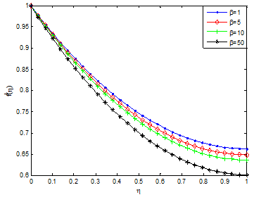
Figure 3A Effects of casson parameter on the velocity profile of Ag-kerosene casson-carreau nanofluid.
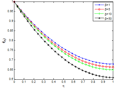
Figure 3B Effects of casson parameter on temperature profile of Cu-kerosene casson-carreau nanofluid.
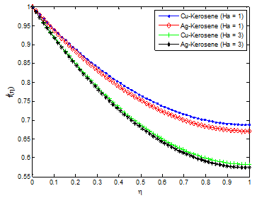
Figure 4 Effect of magnetic field parameter (Hartmann number) on the fluid velocity distribution.
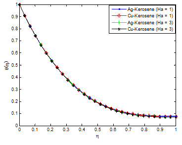
Figure 5 Effect of magnetic field parameter (Hartmann number) on the fluid temperature distribution.
The effects of unsteadiness parameter on velocity and temperature profiles are shown in Figure 6 & Figure 7, respectively. It is observed that increasing values of S increases the velocity field while decreases the temperature field. This is because as the rate of heat loss by the thin film increases as the value of unsteadiness parameter increases. Figure 8 & Figure 9 depict the effects of Weissenberg number (We) on the velocity and temperature profiles. It is shown from the figures that the velocity increases for increasing values of We and opposite trend was observed in temperature field. The observed trends in the velocity and temperature fields are due to the fact that a higher value of We will reduce the viscosity forces of the Carreau fluid. Increasing the Weissenberg number reduces the magnitude of the fluid velocity for shear thinning fluid while it arises for the shear thickening fluid. The influence of aligned angle on velocity and temperature profiles is presented in Figure 10 & Figure 11. From the figures, it is shown that as the value of aligned parameter increases, the velocity field increases while temperature field decreases.
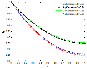
Figure 6 Effect of unsteadiness parameter on the fluid velocity distribution.
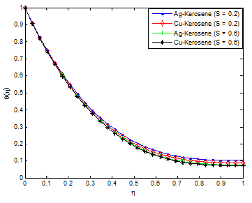
Figure 7 Effect of unsteadiness parameter on the fluid temperature distribution.
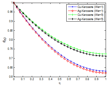
Figure 8 Effect of Weissenberg number on the fluid velocity distribution.

Figure 9 Effect of Weissenberg number on the fluid temperature distribution.
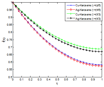
Figure 10 Effect of aligned angle on the fluid velocity distribution.
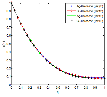
Figure 11 Effect of aligned angle on the fluid temperature distribution.
Figure 12 & Figure 13 demonstrated the effect of power law index on velocity and temperature fields. As the power index is increased, it was observed that the velocity profile increases while the temperature profile decreases. This is because, increasing value of the power law index, thickens the liquid film associated with an increase of the thermal boundary layer. An increase in the momentum boundary layer thickness and a decrease in thermal boundary layer thickness is observed for the increasing values of the power law index including shear thinning to shear thickening fluids. Also, it should be pointed out that an increase in Weissenberg number correspond a decrease in the local skin friction coefficient and the magnitude of the local Nusselt number s decreases when the Weissenberg number increases. The effects of nanoparticles volume fraction on the velocity and temperature profiles are depicted in Figure 14 & Figure 15, respectively. The result shows that as the solid volume fraction of the film increases both the velocity and temperature field increases. This is because as the nanoparticle volume increases, more collision occurs between nanoparticles and particles with the boundary surface of the plate and consequently the resulting friction enhances the thermal conductivity of the flow and gives rise to increase the temperature within the fluid near the boundary region.

Figure 12 Effect of power-law index on the fluid velocity distribution.
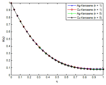
Figure 13 Effect of power-law index on the fluid temperature distribution.

Figure 14 Effect of nanoparticle volume fractions on the fluid velocity distribution.

Figure 15 Effect of nanoparticle volume fractions on the fluid temperature distribution.
Figure 16 & Figure 17 depict the influence of non-uniform heat source/sink parameter on the temperature field. It is revealed that increasing the non-uniform heat source/sink parameter enhances the temperature fields. It is observed in the analysis that the temperature and thermal boundary layer thickness is depressed by increasing the Prandtl number Pr. The effect of Eckert number on temperature profile is shown in Figure 18. It was established that as the values of Eckert number increases, the values of the temperature distributions in the fluid increases. This is because as Ec increases, heat energy is saved in the liquid due to the frictional heating. The effect of nanoparticle volume fraction ϕ on the film thickness of the nanofluid is shown in Figure 19. It is evident from the figure that the film thickness is enhanced as the values of ϕ is increased. It can be inferred from Eq. (12) that if nanoparticle volume fraction ϕ is increased, the nanofluid viscosity will increased as there exist a direct relationship or proportion between the two parameters. As a result, the increasing viscosity resists the fluid motion along the stretching direction leading to the slowdown of the film thinning process.96
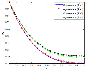
Figure 16 Effect of non-uniform heat source/sink parameter (A*) on the fluid temperature distribution.

Figure 17 Effect of non-uniform heat source/sink parameter (B*) on the fluid temperature distribution.
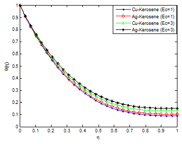
Figure 18 Effect of Eckert number on the fluid temperature distribution.
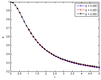
Figure 19 Variation of film thickness h with time t for different values of ϕ.
Conclusion
In this paper, combined influences of thermal radiation, inclined magnetic field and temperature-dependent internal heat generation on unsteady two-dimensional flow and heat transfer analysis of dissipative Casson-Carreau nanofluid over a stretching sheet embedded in a porous medium have been investigated examined. Using kerosene as the base fluid embedded with the silver (Ag) and copper (Cu) nanoparticles, the effects of other pertinent parameters on flow and heat transfer characteristics of the nanofluids are investigated and discussed. From the results, it was established temperature field and the thermal boundary layers of Ag-kerosene nanofluid are highly effective when compared with the Cu-kerosene nanofluid. Thermal and momentum boundary layers of Cu-kerosene and Ag-kerosene nanofluids are not uniform. Heat transfer rate is enhanced by increasing in power-law index and unsteadiness parameter. Skin friction coefficient and local Nusselt number can be reduced by magnetic field parameter and they can be enhanced by increasing in aligned angle. Friction factor is depreciated and the rate of heat transfer increases by increasing the Weissenberg number. This analysis can help in expanding the understanding of the thermo-fluidic behaviour of the Carreau nanofluid over a stretching sheet. Also, the present study has numerous applications involving heat transfer and other applications such as chemical sensors, biological applications, glass, solar energy transformation, electronics, petrochemical products, light-weight, heat-insulating and refractory fiberboard and metallic ceramics etc
Acknowledgements
Conflicts of Interest
The authors declare that there is no conflict of interest regarding the publication of this paper.
Nomenclature
Time-dependent rate
A* Non-uniform heat generation/absorption parameter
B* Non-uniform heat generation/absorption parameter
Bo Electromagnetic induction
Ec Eckert number
M Hartmann number/magnetic field parameter
n Power law index
Pr Prandtl number
Pressure
R Radiation number
Re Permeation Reynolds number
S Unsteadiness parameter
Time
Velocity component in x-direction
Velocity component in y-direction
Fluid inflow velocity at the wall
We Weissenberg number
Coordinate axis parallel to the channel walls
Coordinate axis perpendicular to the channel walls
Symbol
Density of the nanofluid
Density of the fluid
Dynamic viscosity of the nanofluid
Density of the nanoparticles
Fraction of nanoparticles in the nanofluid
Electrical conductivity
Γ Time constant
γ Aligned angle
References
- Hayat T, Ullah I, Ahmad B, et al. Radiative flow of Carreau liquid in presence of Newtonian heating and chemical reaction. Results in Physics. 2017;7:715–722.
- Andersson HI, Aarseth JB, Braudand N, et al. Flow of a Power-Law Fluid on an Unsteady Stretching Surface. J Non-Newtonian Fluid Mech. 1996;62(1):1–8.
- Anderson HI, Bech KH, Dandapat BS. Magneto Hydrodynamics Flow of a Power-Law Fluid Over A Stretching Sheet. Int J Non- Linear Mech. 1992;27(6):929–936.
- Chen CH. Heat Transfer in a Power-Law Fluid Film over an Unsteady Stretching Sheet. Heat Mass Transf. 2003;39(9):791–796.
- Dandapat BS, Santra B, Andersson HI. Thermo Capillarity in a Liquid Film on an Unsteady Stretching Surface. Int J Heat and Mass transfer. 2003;46(16):3009–3015.
- Dandapat BS, Santra B, Vejravelu K. The Effects of Variable Fluid Properties and the Thermo Capillarity on The Flow of a Thin Film On Stretching Sheet. Int J Heat and Mass transfer. 2007;50(6):991–996.
- Wang C. Analytic Solutions for a Liquid Film on an Unsteady Stretching Surface. Heat Mass Transf. 2006;42(8):759–766.
- Chen CH. Effect of Viscous Dissipation on Heat Transfer in a Non-Newtonian Liquid Film over an Unsteady Stretching Sheet. J Nonnewton Fluid Mech. 2006;135(3):128–135.
- Sajid M, Hayat T, Asghar S. Comparison between the HAM and HPM Solutions of Thin Film Flows of Non-Newtonian Fluids on a Moving Belt. Nonlinear Dyn. 2007;50(2):27–35.
- Dandapat BS, Maity S, Kitamura A. Liquid Film Flow Due to an Unsteady Stretching Sheet. Int J Non Linear Mech. 2008;43(9):880–886.
- Abbasbandy S, Yurusoy M, Pakdemirli M. The Analysis Approach of Boundary Layer Equation of Power-Law Fluids of Second Grade. Zzeitschrift fur Naturforschung A. 2008;63(9):564–570.
- Santra B, Dandapat BS. Unsteady Thin Film Flow over A Heated Stretching Sheet. Int J Heat Mass transfer. 2008;52:1965–1970.
- Sajid M, Ali N, Hayat T. On Exact Solutions for Thin Film Flows of A Micropolar Fluid. Commun Nonlinear Sci Numer Simul. 2009;14(2):451–461.
- Noor NFM, Hashim I. Thermocapillarity and Magnetic Field Effects in a Thin Liquid Film on an Unsteady Stretching Surface. Int J Heat and mass Transfer. 2010;53(10):2044–2051.
- Dandapat BS, Chakraborty S. Effects of Variable Fluid Properties on Unsteady Thin-Film Flow over a Non-Linear Stretching Sheet. Int J Heat Mass Transf. 2010;(53):5757–5763.
- Dandapat BS, Singh SK. Thin Film Flow over a Heated Nonlinear Stretching Sheet in Presence of Uniform Transverse Magnetic Field. Int Commun Heat Mass Transf. 2011;38(3):324–328.
- Abdel-Rahman GM. Effect of Magnetohydrodynamic on Thin Films of Unsteady Micropolar Fluid through A Porous Medium. J Mod Phys. 2011;2(11):1290–1304.
- Khan Y, Wu Q, Faraz N, et al. The Effects of Variable Viscosity and Thermal Conductivity on a Thin Film Flow over a Shrinking/Stretching Sheet. Comput Math with Appl. 2011;61(11):3391–3399.
- Liu IC, Megahed A, Wang HH. Heat Transfer in a Liquid Film due to an Unsteady Stretching Surface with Variable Heat Flux. J Appl Mech. 2013;80(4):1–7.
- Vajravelu K, Prasad KV. Unsteady Flow and Heat Transfer in a Thin Film of Ostwald-De Waele Liquid Over A Stretching Surface. Commun Nonlinear Sci Numer Simul. 2012;17(11):4163–4173.
- Liu IC, Megahed AM. Homotopy Perturbation Method for Thin Film Flow and Heat Transfer over an Unsteady Stretching Sheet with Internal Heating and Variable Heat Flux. J Appl Math; 2012.
- Aziz RC, Hashimand I, Abbasbandy S. Effects of Thermocapillarity and Thermal Radiation on Flow and Heat Transfer In A Thin Liquid Film on an Unsteady Stretching Sheet. Math Probl Eng; 2012.
- Khader MM, Megahed AM. Numerical Simulation Using The Finite Difference Method for the Flow and Heat Transfer in a Thin Liquid Film over an Unsteady Stretching Sheet in a Saturated Porous Medium in the Presence of Thermal Radiation. J King Saud Univ Eng Sci. 2013;25(1):29–34.
- Vajravelu K, Hadjinicolaou A. Convective heat transfer in an electrically conducting fluid at a stretching surface with uniform free stream. Int J Eng Sci.1997;35(13):1237–1244.
- Pop I, Na TY. A note on MHD flow over a stretching permeable surface. Mech Res Commun. 1998;25(3):263–269.
- Xu H, Liao SJ, Pop I. Series solutions of unsteady three-dimensional MHD flow and heat transfer in the boundary layer over an impulsively stretching plate. Eur J Mech B-Fluids. 2007;26(1):15–27.
- Ishak A, Nazar R, Pop I. Hydromagnetic flow and heat transfer adjacent to a stretching vertical sheet. Heat Mass Transfer. 2008;44:921.
- Ishak A, Jafar K, Nazar R, et al. MHD stagnation point flow towards a stretching sheet. Physica A: Statistical Mechanics and its Applications. 2009;388(17):3377–3383.
- Abo Eldahab Emad M. Radiation effect on heat transfer in electrically conducting fluid at a stretching surface with uniform free stream. J Phys D Appl Phys. 2000;33(24):3180–3185.
- Gnaneswara Reddy M. Influence of magnetohydrodynamic and thermal radiation boundary layer flow of a nanofluid past a stretching sheet. J Sci Res. 2014;6(2):257–272.
- Abo-Eldahab EM, Elgendy MS. Radiation effect on convective heat transfer in an electrically conducting fluid at a stretching surface with variable viscosity and uniform free stream. Physica Scripta. 2000;62(4):321–325.
- Gnaneswara Reddy M. Thermal radiation and chemical reaction effects on MHD mixed convective boundary layer slip flow in a porous medium with heat source and Ohmic heating. Eur Phys J Plus. 2014;129:41.
- Gnaneswara Reddy M. Effects of thermophoresis, viscous dissipation and joule heating on steady MHD flow over an inclined radiative isothermal permeable surface with variable thermal conductivity. J Appl Fluid Mech. 2014;7(1):51–61.
- Raptis A, Perdikis C. Viscoelastic flow by the presence of radiation. Zeitschrift für Angewandte Mathematik und Mechanik (ZAMM). 1998;78(4):277–279.
- Seddeek MA. Effects of radiation and variable viscosity on a MHD free convection flow past a semi-infinite flat plate with an aligned magnetic field in the case of unsteady flow. Int J Heat Mass Transfer. 2002;45(4):931–935.
- Mabood F, Imtiaz M, Alsaedi A, et al. Unsteady convective boundary layer flow of Maxwell fluid with nonlinear thermal radiation: A Numerical study. Int J Nonlinear Sci Num Simul. 2016;17(5):221–229.
- Hayat T, Muhammad T, Alsaedi A, et al. Magnetohydrodynamic threedimensional flow of viscoelastic nanofluid in the presence of nonlinear thermal radiation. J Magn Magn Mater. 2015;385:222–229.
- Farooq M, Khan MI, Waqas M, et al. MHD stagnation point flow of viscoelastic nanofluid with non-linear radiation effects. J Mol Liq. 2016;221:1097–1103.
- Shehzad SA, Abdullah Z, Alsaedi A, et al. Thermally radiative three-dimensional flow of Jeffrey nanofluid with internal heat generation and magnetic field. J Magn Magn Mater. 2016;397:108–114.
- Lin Y, Zheng L, Zhang X, et al. MHD Pseudo-Plastic Nanofluid Unsteady Flow And Heat Transfer In A Finite Thin Film Over Stretching Surface With Internal Heat Generation. Int J Heat Mass Transf. 2015;84:903–911.
- Sandeep N, Sulochana C, Animasaun IL. Stagnation Point Flow of a Jeffrey Nano Fluid over a Stretching Surface with Induced Magnetic Field and Chemical Reaction. Int J Eng Res Africa. 2016;20:93–111.
- Tawade J, Abel MS, Metri PS, et al. Thin Film Flow and Heat Transfer Over an Unsteady Stretching Sheet with Thermal Radiation, Internal Heating In Presence of External Magnetic Field. Int J Adv Appl Math And Mech. 2016;3(4):29–40.
- Raju CSK, Sandeep N. Unsteady three-dimensional flow of Casson-Carreau fluids past a stretching surface. Alex Eng J. 2016;55(2):1115–1126.
- Raju CSK, Sandeep N. Falkner-Skan flow of a magnetic-Carreau fluid past a wedge in the presence of cross diffusion effects. Eur Phys J Plus. 2016;131:267.
- Raju CSK, Sandeep N, Sugunamma V. Dual Solutions For Three-Dimensional MHD Flow Of A Nanofluid Over A Nonlinearly Permeable Stretching Sheet. Alexandria Engineering Journal. 2016;55(1):151–162.
- Sandeep N, Koriko OK, Animasaun IL. Modified Kinematic Viscosity Model for 3D-Casson Fluid Flow within Boundary Layer Formed On A Surface At Absolute Zero. Journal of Molecular Liquids. 2016;221:1197–1206.
- Babu MJ, Sandeep N, Raju CSK. Heat and Mass Transfer in MHD Eyring-Powell Nanofluid Flow Due To Cone in Porous Medium. International Journal of Engineering Research in Africa. 2016;19:57–74.
- Animasun IL, Raju CSK, Sandeep N. Unequal Diffusivities Case of Homogeneous-Heterogeneous Reactions within Viscoelastic Fluid Flow in the Presence of Induced Magnetic Field and Nonlinear Thermal Radiation. Alexandria Engineering Journal. 2016;55(2):1595–1606.
- Makinde OD, Animasaun IL. Thermophoresis and Brownian Motion Effect on MHD Bioconvection of Nanofluid with Nonlinear Thermal Radiation and Quartic Chemical Reaction Past an Upper Horizontal Surface of A Paraboloid of Revolution. J Mol Liquids. 2016;221:733–743.
- Makinde OD, Animasaun IL. Bioconvection in MHD Nanofluid Flow with Nonlinear Thermal Radiation and Quartic Autocatalysis Chemical Reaction Past an Upper Surface of A Paraboloid of Revolution. Int J Ther Sci. 2016;109:159–171.
- Sandeep N. Effect of Aligned Magnetic Field on Liquid Thin Film Flow of Magnetic-Nanofluid Embedded With Graphene Nanoparticles. Advanced Powder Technology. 2017;28(3):865–875.
- Reddy JVR, Sugunamma V, Sandeep N. Effect Of Frictional Heating on Radiative Ferrofluid Flow over a Slendering Stretching Sheet With Aligned Magnetic Field. Europen Physical Journal Plus. 2017;132:7.
- Ali ME, Sandeep N. Cattaneo-Christov Model for Radiative Heat Transfer of Magnetohydrodynamic Casson-Ferrofluid: A Numerical Study. Results in Physics. 2017;7:21–30.
- Maity S, Ghatani Y, Dandapat BS. Thermocapillary Flow of a Thin Nanoliquid Film Over an Unsteady Stretching Sheet. Journal of Heat Transfer. 2016;138(4):042401.
- Hayat T, Khan MI, Farooq M, et al. Impact of Cattaneo-Christov heat flux model in flow of variable thermal conductivity fluid over a variable thicked surface. International Journal of Heat and Mass Transfer. 2016;99:702–710.
- Hayat T, Khan MI, Farooq M, et al. Stagnation point flow with Cattaneo-Christov heat flux and homogeneous-heterogeneous reactions. Journal of Molecular Liquids. 2016;220:49–55.
- Khan MI, Waqas M, Hayat T, et al. A comparative study of Casson fluid with homogeneous-heterogeneous reactions. J Colloid Interface Sci. 2017;498:85–90.
- Khan MI, Hayat T, Alsaedi A. Activation energy impact in nonlinear radiative stagnation point flow of Cross nanofluid. International Communications in Heat and Mass Transfer. 2018;91:216–224.
- Hayat T, Ijaz Khan M, Qayyum S, et al. New thermodynamics of entropy generation minimization with nonlinear thermal radiation and nanomaterials. Physics Letters A. 2018;382(11):749–760.
- Hayat T, Nawaz S, Alsaedi A. Entropy generation in peristalsis with different shapes of nanomaterial. Journal of Molecular Liquids. 2017;248:447–458.
- Hayat T, Khan MI, Khan TA, et al. Entropy generation in Darcy-Forchheimer bidirectional flow of water-based carbon nanotubes with convective boundary conditions. Journal of Molecular Liquids. 2018;265:629–638.
- Hayat T, Waleed M, Khan A, et al. Nonlinear radiative heat flux and heat source/sink on entropy generation minimization rate. Physica B: Condensed Matter. 2018;538:95–103.
- Khan MI, Qayyum S, Hayat T, et al. Entropy generation minimization and binary chemical reaction with Arrhenius activation energy in MHD radiative flow of nanomaterial. Journal of Molecular Liquids. 2018;259:274–283.
- Khan MI, Qayyum S, Hayat T, et al. Entropy generation in flow with silver and copper nanoparticles. Colloids and Surfaces A. 2018;539:335–346.
- Khan MI, Qayyum S, Hayat T, et al. Entropy generation in magnetohydrodynamic radiative flow due to rotating disk in presence of viscous dissipation and Joule heating. Physics of Fluids. 2018;30(1):017101.
- Waleed M, Khan A, Khan MI, et al. Entropy generation minimization (EGM) of nanofluid flow by a thin moving needle with nonlinear thermal radiation. Physica B: Condensed Matter. 2018;534:113–119.
- Khan MI, Ullah S, Hayat T, et al. Entropy generation minimization (EGM) for convection nanomaterial flow with nonlinear radiative heat flux. Journal of Molecular Liquids. 2018;260:279–291.
- Khan NB, Ibrahima Z, Khan MI, et al. VIV study of an elastically mounted cylinder having low mass-damping ratio using RANS model. International Journal of Heat and Mass Transfer. 2018;121:309–314.
- Hayat T, Ijaz Khan M, Qayyum S, et al. Modern developments about statistical declaration and probable error for skin friction and Nusselt number with copper and silver nanoparticles. Chinese Journal of Physics. 2017;55(6):2501–2513.
- Khan MI, Waqas M, Hayat T, et al. Numerical simulation of nonlinear thermal radiation and homogeneous-heterogeneous reactions in convective flow by a variable thicked surface. Journal of Molecular Liquids. 2017;246:259–267.
- Hayat T, Khan M, Khan MI, et al. Electromagneto squeezing rotational flow of Carbon (C)-Water (H2O) kerosene oil nanofluid past a Riga plate: A numerical study. PLOS ONE. 2017;12(8):e0180976.
- Khan MI, Qayyuma S, Hayata T, et al. Entropy generation in radiative motion of tangent hyperbolic nanofluid in presence of activation energy and nonlinear mixed convection. Physics Letters A. 2018;31:2017–2026.
- Carreau PJ. Rheological equations from molecular network theories. Trans Soc Rheol. 1972;16(1):99–127.
- Kumar MS, Sandeep N, Kumar BR. Free convection Heat transfer of MHD dissipative Carreau Nanofluid Flow Over a Stretching Sheet. Frontiers in Heat and Mass Transfer. 2017;13:8.
- Hayat T, Saleem N, Asghar S, et al. Influence of induced magnetic field and heat transfer on peristaltic transport of a Carreau fluid. Commun Nonlinear Sci Numer Simul. 2011;16(9):3559–3577.
- Olajuwon BI. Convective heat and mass transfer in a hydromagnetic Carreau fluid past a vertical porous plated in presence of thermal radiation and thermal diffusion. Therm Sci. 2011;15(Suppl 2):241–252.
- Hayat T, Asad S, Mustafa M, et al. Boundary layer flow of Carreau fluid over a convectively heated stretching sheet. Appl Math Comput. 2014;246:12–22.
- Akbar NS, Nadeem S, Haq Rizwan UI, et al. MHD stagnation point flow of Carreau fluid toward a permeable shrinking sheet: Dual solutions. Ain Shams Eng J. 2014;5(4):1233–1239.
- Akbar NS. Blood flow of Carreau fluid in a tapered artery with mixed convection. Int J Biomath. 2014;7(6):1450068.
- MekheimerKh S, Salama F, El Kot MA. The unsteady flow of a carreau fluid through inclined catheterized arteries haveing a balloon with Time-Variant Overlapping Stenosis. Walailak Journal of Science and Technology (WJST). 2015;12(10):863–883.
- Elmaboud YA, Mekheimer KS, Mohamed MS. Series solution of a natural convection flow for a Carreau fluid in a vertical channel with peristalsis. J Hydrodyn Ser B. 2015;27(6):969–979.
- Hashim, Khan M. A revised model to analyze the heat and mass transfer mechanisms in the flow of Carreaunanofluids. Int J Heat Mass Transfer. 2016;103:291–297.
- Machireddy GR, Naramgari S. Heat and mass transfer in radiative MHD Carreau fluid with cross diffusion. Ain Shams Eng J; 2016.
- Sulochana C, Ashwinkumar GP, Sandeep N. Transpiration effect on stagnation point flow of a Carreau nanofluid in the presence of thermophoresis and Brownian motion. Alex Eng J. 2016;55(2):1151–1157.
- Casson N. Rheology of Dispersed System. Oxford, UK: Pergamon Press; 1959.
- Casson N. A flow equation for the pigment oil suspension of the printing ink type. In: Rheology of Disperse Systems, New York: Pergamon; 1959. 84–102p.
- Dash RK, Mehta KN, Jayaraman G. Casson fluid flow in a pipe filled with a homogeneous porous medium. International Journal of Engineering Science. 1996;34(10):1145–1156.
- Andersson HI, Dandapat BS. Flow of a power-law fluid over a stretching sheet. International Journal of Non-Linear Mechanics. 1992;27(6):929–936.
- Sajid M, Ahmad I, Hayat T, et al. Unsteady flow and heat transfer of a second grade fluid over a stretching sheet. Communications in Nonlinear Science and Numerical Simulation. 2009;14(1):96–108.
- Eldabe NTM, Salwa MGE. Heat transfer of mhd non-Newtonian Casson fluid flow between two rotating cylinder. Journal of the Physical Society of Japan. 1995;64:41–64.
- Nadeem S, Haq RL, Akbar NS, et al. MHD three-dimensional Casson fluid flow past a porous linearly stretching sheet. Alexandria Engineering Journal. 2013;52(4):577–582.
- Al Kalbani KS, Alam MS, Rahman MM. Finite Element Analysis of Unsteady Natural Convective Heat Transfer and Fluid Flow of Nanofluids inside a Tilted Square Enclosure in the Presence of Oriented Magnetic Field. Columbia International Publishing American Journal of Heat and Mass Transfer. 2016;3(3):186–224.
- Swapna G, Lokendra Kumar, Puneet Rana, et al. Finite element study of radiative double-diffusive mixed convection magneto-micropolar flow in a porous medium with chemical reaction and convective condition. Alexandria Engineering Journal. 2018;57(1):107–120.
- Abel MS, Mahesha N, Tawade J. Heat transfer in a liquid film over an unsteady stretching surface with viscous dissipation in presence of external magnetic field. Applied Mathematical Modelling. 2009;33(8):3430–3441.
- Akbar NS, Nadeem S, Haq RUI, et al. MHD stagnation point flow of Carreau fluid toward a permeable shrinking sheet: dual solutions. Ain Shams Eng J. 2014;5(4):1233–1239.
- Maity S, Ghatani Y, Dandapat BS. Thermocapillary Flow of a Thin Nanoliquid Film Over an Unsteady Stretching Sheet. Journal of Heat Transfer. 2016;138(4):042401.

©2018 Sobamowo, et al. This is an open access article distributed under the terms of the,
which
permits unrestricted use, distribution, and build upon your work non-commercially.


