For a heat engine working between two heat reservoirs, a hot reservoir at high temperature TH and a cold temperature at low temperature TL, what is the maximal achievable efficiency by the heat engine? This question was answered by Sadi Carnot at the beginning of the 19th century by using methods of thermodynamics.1-2 It was found that the maximal efficiency is limited by the Carnot efficiency
. It is well known that the Carnot cycle is the most efficient cycle operating between these specified temperature limits. The Carnot cycle includes four branches: isentropic compression, isothermal heat addition, isentropic expansion and isothermal heat rejection.3 The Carnot cycle is an idealized thermodynamic cycle and is not appropriate to describe real heat engines such as air standard cycles. The Otto cycle, named after Nikolaus A. Otto, is the ideal cycle for spark-ignition reciprocating engines. The Otto cycle describes the ideal behavior of spark-ignition engines, in which the piston traces four strokes (four-stroke internal combustion engine). The internal combustion engine has intake and exhaust valves. These valves are closed during compression and expansion and they are open while exchanging intake (air mixture) and exhaust (combustion gases).3 The Brayton cycle, named after George Brayton, is used to describe the behavior of the reciprocating oil-burning engine that was developed by Brayton around 1870. The Brayton cycle is used today to describe the behavior of gas turbines which includes four processes: isentropic compression and expansion, and constant pressure heat addition and rejection. The working fluid is ideal gas.3
Stirling and the Ericsson engines are considered external combustion engines. That is, the energy flows to the cylinder from outside. External combustion has some advantages compared to internal combustion. Among these is the flexibility of choosing thermal energy sources, less air pollution due to complete combustion, more efficient use of energy sources, closed cycles operation which enables choosing best working fluids such as Hydrogen and Helium. The Stirling engine includes four processes: isothermal compression, isochoric heat addition, isothermal expansion and isochoric heat rejection. The Ericsson cycle differs from the Stirling cycle by the heat addition and heat rejection processes. While in the Stirling cycle these are isochoric processes, in the Ericsson cycle they are isobaric processes.3 Curzon & Ahlborn4 investigated the efficiency of a heat engine at maximum power operation in finite time.5-10 They considered in 1975 a model of heat engine (usually called the Curzon-Ahlborn engine) with finite heat transfer rates. The heat engine produces zero power output in the extremes of very slow operation and very fast operation. It was found that the heat engine attains a maximum power point with the efficiency at this point being one minus the square root of the ratio between the temperature of the cold reservoir and the temperature of the hot reservoir
. Bejan11 showed in 1994 that this result of heat engine efficiency at maximum power operation was previously derived by Novikov12 in 1957 when analyzing the performance of nuclear power plants.
Harvey S Leff13 considered four air standard cycles (Otto, Disel, Brayton, Atkinson) and found that the efficiency of these cycles at maximum power operation is similar to the achieved result by Curzon-Ahlborn. The methods of irreversible thermodynamics and finite thermodynamics have been used to analyze thermodynamic systems.14-32 Analysis of the air standard cycles (Otto and others) could be found elsewhere.33-60 In this article we ask: what are the effective temperature and the effective efficiency of a heat engine working between two heat reservoirs for the cycles described above? The answers to these questions are given in the following paragraphs. The following sections describe: the SOT function in section II, the model of the heat engine in section III; the Carnot cycle is considered in section IV, the air standard cycles are considered in section V, numerical examples are given in section VI, and finally summary and conclusions are given in section VII.
For a thermal process that goes from state A to state B, the negative integral of the heat transfer change divided by the square of the temperature from state A to state B is given by (a new function introduced in this article and it is called by the author the SOT function):
(1)
For isothermal process the SOT function is given by:
(2)
The first law of thermodynamics for a process with ideal gas working fluid is given by:
(3)
By considering the various process types and using the first law of thermodynamics (eq. 3), makes it easy to write explicit forms of the SOT function. In the following subsections some typical processes are considered.
Constant volume process
For the constant volume process (v=const.), the heat transfer change is proportional to the temperature change (dT) with constant volume heat capacity proportionality factor (cv). In this case the SOT function is given by:
(4)
Constant pressure process
For the constant pressure process (p=const.), the heat transfer change is proportional to the temperature change (dT) with constant pressure heat capacity proportionality factor (cp). In this case the SOT function is given by:
(5)
Constant temperature process
For the constant temperature process (T=const.), the heat transfer change is proportional to the volume change (dv) with pressure proportionality factor (p). In this case the SOT function is given by:
(6)
Isentropic process
For the isentropic process-constant entropy process (s=const.), the heat transfer change is zero. In this case the SOT function is given by:
(7)
For a heat engine going in a cycle the SOT function is given by:
(8)
Consider a heat engine working between two heat reservoirs, a hot reservoir at high temperature (TH) and a cold reservoir at low temperature (TL). The schematics of the heat engine are depicted in Figure 1.
The net work output wnet is calculated by means of the first law of thermodynamics (eq. 3) and is given by:
(9)
The SOT function is given by equation (8).
The effective temperature is defined as the square root of the ratio between the net work output and the SOT function, and is given by:
(10)
Finally, the effective efficiency is defined as the difference between unity minus the ratio between the low temperature and the effective temperature, and is given by:
(11)
The schematic of the Carnot heat engine is depicted in Figure 1. The net work output is given by (eq. 9). The Carnot cycle includes two processes: heat addition and heat rejection at constant temperatures (high and low) connected with two isentropic (reversible adiabatic) processes. The entropy of the heat engine is calculated by means of the second law of thermodynamics and is given by:
(12)
By applying the assumptions of the Carnot cycle, equation (12) could be written explicitly as follows:
(13)
The SOT function for the Carnot cycle is derived by means of equation 1 and is given by:
(14)
Applying equation (13) to equation (4) aids to simplify the expression for the SOT function. After algebraic manipulation and using equation (9), the SOT function of the Carnot heat engine simplifies to the following:
(15)
Then, the effective temperature is defined as the geometric mean of the high temperature and the low temperature, a result suggested by (eq. 15) and is given by:
(16)
Finally, the effective efficiency for the Carnot heat engine is given by:
(17)
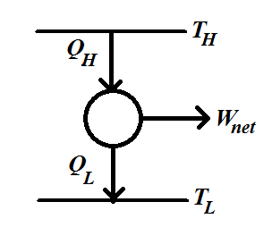
Figure 1 Schematics of the engine working between two heat reservoirs, a hot reservoir at high temperature TH and a cold reservoir at low temperature TL. The heat input to the heat engine is QH and the heat rejection from the heat engine is QL. The net work output wnet is given by the QH-QL.
Ideal Otto cycle
The ideal Otto cycle is used to estimate the efficiency of spark ignition (SI) engine (Otto engine). The schematic of the Pressure–Volume (P-V) diagram of the ideal Otto cycle is shown in Figure 2. The cycle includes four processes: 1à2 isentropic compression, 2à3 constant volume heat addition, 3à4 isentropic expansion, and 4à1 constant volume heat rejection.
For a given initial state (pressure P1, volume V1, temperature T1) with known highest temperature T3, the application of the thermodynamic state relations and the first law of thermodynamics of the different branches lead to the following results:
The heat input to the engine QH is given by:
(18)
Where cv is the constant volume heat capacity, is the ratio between T1 and T3 and a () is the compression ratio r raised to the power (k-1) with k equals the ratio between constant pressure heat capacity (cp) and constant volume heat capacity (k=cp/cv).1
The heat rejection from the engine is given by:
(19)
Where T4 is the temperature at state 4.
The net work output (wnet) extracted by the engine is given by:
(20)
The SOT function is calculated based on equation (8). Noting that the contributions of the isentropic branches to the SOT function are zero, the resulting SOT function for the ideal OTTO cycle is given by:
(21)
By comparing equations (20) and (21) it is observed that the effective temperature could be deduced and is given by:
(22)
The effective efficiency for the ideal OTTO cycle is given by equation (17), where
is replaced by
and
is replaced by
.
Ideal Brayton cycle
The ideal Brayton cycle is used to estimate the efficiency of gas turbines. The schematic of the Pressure–Volume (P-V) diagram of the ideal Brayton cycle is shown in Figure 3. The Brayton cycle includes four processes: 1à2 isentropic compression, 2à3 constant pressure heat addition, 3à4 isentropic expansion, and 4à1 constant pressure heat rejection.
For a given initial state (pressure P1, volume V1, temperature T1) with known highest temperature T3, the application of the thermodynamic state relations and the first law of thermodynamics of the different branches lead to the following results:
The heat input to the engine QH is given by:
(23)
Where cp is the constant pressure heat capacity,
is the ratio between T1 and T3 and a (
) is the compression ratio r raised to the power (k-1) with k equals the ratio between constant pressure heat capacity (cp) and constant volume heat capacity (k=cp/cv).
The heat rejection from the Brayton cycle is given by:
(24)
Where T4 is the temperature at state 4.
The net work output (wnet) extracted by the Brayton cycle is given by:
(25)
The SOT function is calculated based on equation (8). Noting that the contributions of the isentropic branches to the SOT function are zero, the resulting SOT function for the ideal Brayton cycle is given by:
(26)
By comparing equations (25) and (26) it is observed that the effective temperature could be deduced and is given by:
(27)
The effective efficiency the ideal Brayton cycle is given by equation (17), where
is replaced by
and
is replaced by
.
Ideal Stirling cycle
The ideal Stirling cycle is used to estimate the efficiency of Stirling engine. The schematic of the Pressure–Volume (P-V) diagram of the ideal Stirling cycle is shown in Figure 4. The cycle includes four processes: 1à2 isothermal compression, 2à3 constant volume heat addition, 3à4 isothermal expansion, and 4à1 constant volume heat rejection.
For a given initial state (pressure P1, volume V1, temperature T1) with known highest temperature T3, the application of the thermodynamic state relations and the first law of thermodynamics of the different branches lead to the following results:
The heat input to the Stirling cycle QH is given by:
(28)
Where cv is the constant volume heat capacity,
is the ratio between T1 and T3 and a (
) is the compression ratio r raised to the power (k-1) with k equals the ratio between constant pressure heat capacity (cp) and constant volume heat capacity (k=cp/cv).
The heat rejection from the Stirling cycle is given by:
(29)
Where T4 is the temperature at state 4 and R is the ideal gas constant.
The net work output (wnet) extracted by the Stirling cycle is given by:
(30)
The SOT function is calculated based on equation (8). Noting that the contributions of the isothermal branches to the SOT function cancel each other, the resulting SOT function for the ideal Stirling cycle is given by:
(31)
By comparing equations (30) and (31) it is observed that the effective temperature could be deduced and is given by:
(32)
The effective efficiency the ideal OTTO cycle is given by equation (17), where is replaced by and is replaced by.
Ideal Ericsson cycle
The ideal Ericsson cycle is used to estimate the efficiency of the Ericsson engine. The schematics of the Pressure–Volume (P-V) diagram of the ideal Ericsson cycle is shown in Figure 5. The cycle includes four processes: 1à2 isothermal compression, 2à3 constant pressure heat addition, 3à4 isothermal expansion, and 4à1 constant pressure heat rejection.
For a given initial state (pressure P1, volume V1, temperature T1) with known highest temperature T3, the application of the thermodynamic state relations and the first law of thermodynamics of the different branches lead to the following results:
The heat input to the engine QH is given by:
(33)
Where cv is the constant volume heat capacity,
is the ratio between T1 and T3 and a (
) is the compression ratio r raised to the power (k-1) with k equals the ratio between constant pressure heat capacity (cp) and constant volume heat capacity (k=cp/cv).
The heat rejection from the engine is given by:
(34)
Where T4 is the temperature at state 4.
The net work output (wnet) extracted by the engine is given by:
(35)
The SOT function is calculated based on equation (8). Noting that the contributions of the isobaric branches to the SOT function cancel each other, the resulting SOT function for the ideal Ericsson cycle is given by:
(36)
By comparing equations (35) and (36) it is observed that the effective temperature could be deduced and is given by:
(37)
The effective efficiency the ideal OTTO cycle is given by equation (17). where
is replaced by
and
is replaced by
.
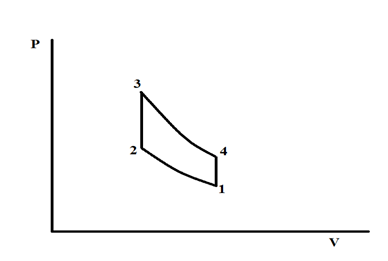
Figure 2 Schematics if the ideal Otto cycle.
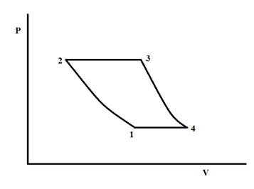
Figure 3 Schematics if the ideal Brayton cycle.
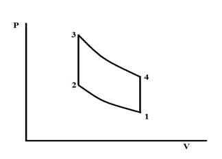
Figure 4 Schematics if the ideal Stirling cycle.
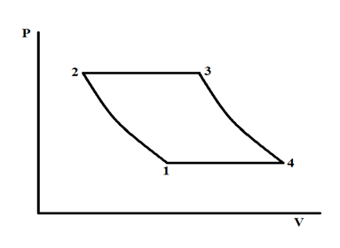
Figure 5 Schematics if the ideal Ericsson cycle.
None.


