The research results relate to the problem of a rational choice of the executive bodies of the spacecraft stage control system of the launch vehicle. Consider the motion of the space stage of a carrier rocket, which is controlled by a roll of engine of small thrust, and by pitch and heading, by a mash engine. Pitch and course control is achieved by deflecting the vector P of the traction force of the marching engine of the space stage in the planes xoy, xoz of the associated coordinate system1 from its longitudinal axis by angles
, respectively.
Figure 1 & 2 contain diagrams that illustrate the action of forces and moments of force on the LV stage when the vector P deviates from the longitudinal axis of the space stage of the nostel rocket.2
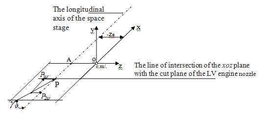
Figure 1 Scheme of action on the space step of the force P in the xoz plane related coordinate system.
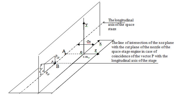
Figure 2 Scheme of action on the space stage of the engine thrust P in the xoy plane related coordinate system.
On the diagrams: OXYZ-a linked coordinate system, a с.m. is the center of mass of the stage, (-
) is the mass asymmetry value (it is assumed that the center of mass of the stage coincides with the point of the negative half-plane; <0, (Figure 1);
-the angle of deviation of the vector P from the plane parallel to the plane XOY and such that it passes through the longitudinal axis of the stage. The force P (when asymmetry
and angle
are obvious) forms a moment
around the axis
, the vector of which is directed along the axis
. Component-
is disturbing moment; component
is moment, which may be the moment controlling.
Usually, angle
and
Note, that a
are functions of time. The non-stationarity
is caused by the non-stationarity of a parameter
, that changes in time due to the emptying in flight of the fuel tanks of the space stage of the launch vehicle (a process independent of the control system), while the non-stationarity
depends on the angle
, which varies in accordance with the control commands.
Figure 2 shows that P, in the presence of an asymmetry
and an angle
, forms around the axes
moments
,
.
The components
of the vector P (Figure 1-3) act in a plane parallel to the plane
.
From Figure 3 it follows that the component of the force P creates a moment
. If the center of mass of the stаge does not coincide with the point of the plane
, then the force
also creates a moment around the axis
.
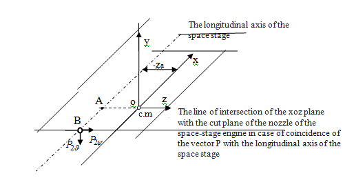
Figure 3 Scheme of action on the LV stage of components P, which create moments of forces around the longitudinal axis.
The components
of the moments of forces around the axis
do not create. An analysis of Figure 1& 2 shows that the swing of the vector P around the point of the longitudinal axis of the LV stage, when the mass asymmetry of the stage is obvious, creates moments of forces around the center of mass of the stage, which can be used to control the movement of the stage along pitch, heading, and roll. As an example, to illustrate what was skozhennogo, the effect of the application of the proposed method when controlling the movement of the 3rd stage of the modern launch vehicle with the following characteristics is considered.3
- The rated thrust of the main engine in the void is 7916 kgf,
- Shift of the geometric axis of the engine chamber relative to the axis of the frame, mm, not more than 2;
- Deviation of the axis of the engine chamber from the perpendicular to the plane of the junction of the engine with the frame, under load, not more than 15 arc minutes (~25 arc degrees).
- Mass asymmetry, m, not more than: - at the beginning of the movement
=0.003,
=0.0085,
at the end of the movement
=0.017,
=0.05.
- Central principal axial moments of inertia: -at the beginning of the movement
at the end of the movement
- The shoulder of the control forces in pitch, heading, m:
- at the beginning of the movement
,
- at the end of the movement
.
- The distance of the center of mass of the step from the longitudinal axis the:
- in the beginning of the movement
- at the end of the movement
.
- The distance of the center of mass of the step from the tip of his nose, m:
- at the beginning of the movement
,
- at the end of the movement
.
- The duration of the perturbed movement of the stage: 470 s.
- The total length of the stage launch vehicle, m:13.
The step control (standard option) in pitch and course is provided by swinging the combustion chamber of the marching engine in the planes of the associated coordinate system,1 in roll by jet thrust engines that create the thrust moment vector directed along the longitudinal axis of the stage. Mathematical modeling of the process of controlling the angular movement of the third stage of a modern launch vehicle,3 that is controlled by pitch and heading by swinging the vector P, was performed using the MathCad software package for a PC. The mathematical model of the motion of the space stage of the launch vehicle was built taking into account unsteady masses, moments of inertia, coordinates of the central masses, and parameters of the motion of the stage.
Models of unsteady characteristics, parameters, disturbing and controlling moments of forces were written as
Here are
the control moments for the course (pitch), roll;
-disturbing, controlling moments on the roll;
- perturbations of pitch angles, course, roll, respectively;
is the distance from the center of the mas stage to the planes xoz, xoy, respectively;
is the angle between the projection of the vector P on the plane xoz (xoy) and the axis ox.
The initial data for the simulation was recorded on the Mathcad worksheet as follows:
, P:=7916, K0:=0.5, K1:=0.25, K01:=0.5, K11:=0.2, T:=0.01. Here K0, K1, K01, K11 are the transfer coefficients, T is the time constant of the control system, - the state vector is transposed. The function D (t, x)-the function of calculating the first derivatives was written in the form:
-team for mathematical modeling.
Character Mappings Introduced:
From Figure 4-6 it follows: the initial perturbations
of the parameters of the stage motion are worked out quite qualitatively.
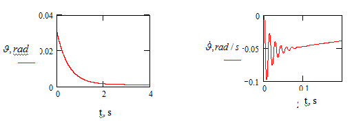
Figure 4 Time variation of perturbations of the step motion parameters.
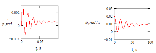
Figure 5 Time variation of perturbations of the step motion parameters.
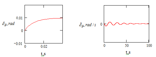
Figure 6 Time variation of perturbations of the stage motion parameters.
Let us carry out a simplified analytical and further refined numerical analysis of the processes of working out disturbances of the parameters of the stage motion by swinging the marching engine and compare them with the processes of working out disturbances by steering engines in two in the pitch and course channels.
In the case of a simplified analysis, it is permissible to use the method of “frozen” coefficients and the principle of superposition, which are often used in problems of rocket dynamics.1-3 Let us consider separately the processes of developing perturbations of the parameters of the motion of space stages of the LV from mass asymmetry and skew line of action of the vector P of the thrust of the main engine of the stage relative to its longitudinal axis due to errors in the manufacture, assembly, installation of the stage and its propulsion system.
We write the mathematical models for working out perturbations in the form:
- Equations (1, 2) when controlling the swing stage in the hinge of the mid-flight engine
- Equations (3, 4) when controlling a stage with steering engines
In equations 1-4, the angles of deviation of the line of action of the thrust vector P of the marching engine thrust from the longitudinal axis of the stage, due to errors in the manufacture, assembly, installation of the foot, its propulsion system (excitation factor) and due to the control commands of the control system, aimed at working out perturbations of the stage motion parameters respectively;
- the angle of deviation of the steering engine from the neutral position in accordance with the commands of the stage control system, aimed at working out perturbations of the motion parameters.
In steady-state modes of motion, the values
are zero and we obtain:
1).
-from the of equations (1), and
-from the equations of system (2).
2).
,
- from equations of systems (3), (4), respectively.
Thus, when controlling the movement of a stage by swinging the main engine, the zeroing of disturbances in the parameters of the stage motion is achieved by reducing the disturbing factors by turning the main engine in a hinge. The refined numerical analysis of the processes of working out the disturbances of the motion parameters by swinging the main engine and steering engines is carried out according to the results of mathematical modeling of the stage stabilization processes using the Mattcad programs.
Initial data:
,
At characteristic times, the control parammeter
takes values
The results of modeling the processes of stabilizing the movement of the LV stage by steering engines
Initial data: К0=:0.1 К1=:0.5 Т=:0.01 а=:1000
The control parameter
takes the following values at characteristic times
The amount of energy required for working out perturbing effects on the movement of the LV stage during a 100s flight when using a marching engine is characterized by an estimate
,
when using steering engines (
) characterize the value
The values of the integrated estimates of energy costs, determined from the presented results of mathematical modeling, are as follows:.
.
An examination of the processes (Figures 7–10) of testing the disturbances of the parameters of the LV stage motion, analysis of the results of mathematical modeling of these processes show the following:
- The main engine as the executive body of the spacecraft stage control system of the LV with mass asymmetry relative to the longitudinal axis provides stage control with a reduction in the influence of disturbing factors,
- The effect of decreasing the value of the perturbing factor is accompanied by a decrease in the amount of energy (fuel) necessary for working out perturbations of the parameters of the LV stage motion.

Figure 7 Time variation of perturbations of the stage motion parameters
,
.

Figure 8 Hafiki time variation of the control parameter
.
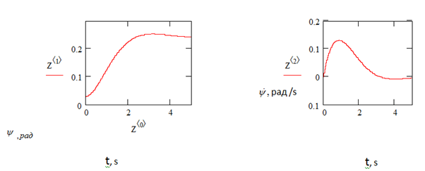
Figure 9 Time variation of perturbations of the stage motion parameters
,
.
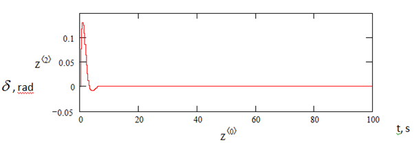
Figure 10 Gaifik changes in time of the control parameter
.


