Submit manuscript...
eISSN: 2576-4543

Physics & Astronomy International Journal

Mini Review Volume 2 Issue 1

Comparison of EDFA and Raman amplifiers effects on RZ and NRZ encoding techniques in DWDM optical network with bit rate of 80 Gb/s

Seraji FE, Kiaee MS

Optical Communication Group, Iran Telecom Research Center, Tehran, Iran

Correspondence: Faramarz Seraji, Optical Communication Group, Iran Telecom Research Center, End of North Kargar Ave., Tehran, Iran, Fax 98-21-84274426

Received: December 24, 2017 | Published: February 20, 2018

Citation: Seraji FE, Kiaee MS. Comparison of EDFA and Raman amplifiers effects on RZ and NRZ encoding techniques in DWDM optical network with bitrate of 80 Gb/s. Phys Astron Int J. 2018;2(1):116-121. DOI: 10.15406/paij.2018.02.00057

Download PDF

Abstract

Transmission of data through the communication networks is possible by using different methods of modulation and encoding. The aim of using these techniques is to efficiently use bandwidth and transmission of digital data by using carrier waves. There is no exception for optical communication systems in which we transmit optical pulses via the light waves. Yet, propagation of the light wave through the optical fibers would incur power loss due to different attenuation mechanisms. Such a situation will cause errors in detection of signals at the receiver end. So, to circumvent this problem, use of optical amplifiers is required. Erbium-doped fiber amplifier (EDFA) and Raman amplifier (RA) are the most popular ones, which are used widely in the optical communications systems. In this study, by simulating a DWDM optical link with a bit rate of 80 Gb/s and a link span of 80 km, the effects of EDFA and RA on NRZ and RZ encoding techniques for modulation are investigated by using Optisystem software solver and the received optical signals are analyzed by the corresponding eye-diagrams and Q-factors.

Keywords: EDFA, raman amplifiers, RZ and NRZ encoding, DWDM Optical Link, 80 Gb/s bit rate

Abbreviations

EDFA, erbium-doped fiber amplifier; RA, raman amplifier; NRZ, non-return-to-zero; DWDM, dense wavelength division multiplexing; CW, continuous wave; SNR, signal-to-noise ratio; NZDSF, non-zero dispersion shifted fiber; RZ, return-to-zero; DCF, dispersion compensating fiber; BER, bit error rate

Introduction

The demand for optical networks with a high bit rate at a long transmission distance is growing at yearly basis.1,2 The signal transmission in optical networks experiences propagation attenuations along a long span of optical fiber links, which in units of dB/km is defined by α=(10/L)log( P o / P in ) MathType@MTEF@5@5@+= feaagKart1ev2aqatCvAUfeBSjuyZL2yd9gzLbvyNv2CaerbuLwBLn hiov2DGi1BTfMBaeXatLxBI9gBaerbd9wDYLwzYbItLDharqqtubsr 4rNCHbGeaGqipG0di9qqqrpepC0xbbL8F4rqqrFfpeea0xe9Lq=Jc9 vqaqpepm0xbba9pwe9Q8fs0=yqaqpepae9pg0FirpepeKkFr0xfr=x fr=xb9adbaqaaeGacaGaaiaabaqaamaabaabaaGcbaqcLbsacqaHXo qycqGH9aqpcqGHsislcaGGOaGaaGymaiaaicdacaGGVaGaamitaiaa cMcaciGGSbGaai4BaiaacEgacaGGOaGaamiuaOWaaSbaaKazba4=ba qcLbmacaWGVbaajeaybeaajugibiaac+cacaWGqbqcfa4aaSbaaKaz ba4=baqcLbmacaWGPbGaamOBaaqcKfaG=hqaaKqzGeGaaiykaaaa@518E@ , where P in MathType@MTEF@5@5@+= feaagKart1ev2aqatCvAUfeBSjuyZL2yd9gzLbvyNv2CaerbuLwBLn hiov2DGi1BTfMBaeXatLxBI9gBaerbd9wDYLwzYbItLDharqqtubsr 4rNCHbGeaGqipG0di9qqqrpepC0xbbL8F4rqqrFfpeea0xe9Lq=Jc9 vqaqpepm0xbba9pwe9Q8fs0=yqaqpepae9pg0FirpepeKkFr0xfr=x fr=xb9adbaqaaeGacaGaaiaabaqaamaabaabaaGcbaqcLbsacaWGqb qcfa4aaSbaaKazba4=baqcLbmacaWGPbGaamOBaaqcKfaG=hqaaaaa @3E37@  is the input power to the fiber and P o MathType@MTEF@5@5@+= feaagKart1ev2aqatCvAUfeBSjuyZL2yd9gzLbvyNv2CaerbuLwBLn hiov2DGi1BTfMBaeXatLxBI9gBaerbd9wDYLwzYbItLDharqqtubsr 4rNCHbGeaGqipG0di9qqqrpepC0xbbL8F4rqqrFfpeea0xe9Lq=Jc9 vqaqpepm0xbba9pwe9Q8fs0=yqaqpepae9pg0FirpepeKkFr0xfr=x fr=xb9adbaqaaeGacaGaaiaabaqaamaabaabaaGcbaqcLbsacaWGqb qcfa4aaSbaaKazba4=baqcLbmacaWGVbaajqwaa+Fabaaaaa@3D4A@  denotes the output power at the fiber end.3 To compensate this loss of signal power, Erbium-doped fiber amplifier (EDFA) and Raman amplifiers are usually used along the transmission link.3

In an optical link, optical amplifiers are usually employed in different arrangements. For instance, a booster amplifier is utilized in the optical transmitter in order to amplify the optical signal before launching into optical fiber.4 The purpose of this amplifier is to compensate the losses incurred in optical devices such as modulator and multiplexer, etc. In addition, the optical signal loses energy while propagating through optical fiber. To compensate this loss, in-line optical amplifier is used. At the final stage of transmission, for enhancing the detection sensitivity of the photodetector at the receiver end, a preamplifier is employed.

The operating principle of EDFA is based on the excitation of Erbium ions in the active region by the signal propagating at operating wavelength in the region of 1550nm. The excited ions while on return to ground state would emit photons in the wavelength range of 1520nm to 1570nm that is accompanied with additional noise.5 On continuation of ion excitations, more photons will emit and the attenuated signal will be amplified, accordingly.6,7

When an optical pulse is launched into a silica fiber along with a continuous wave (CW) pumping beam, its frequency is up-shifted by so-called Raman shift for which the Raman gain becomes maximum. Than the optical pulse is amplified with an effective local gain coefficient.3,8 Since implementation of Raman amplifier needs no separate optical fiber, one can use some portion of transmission fiber for amplification purposes.3

Due to use of the operating wavelength in 1550nm window of optical communication systems and widely utilization of the EDFA and Raman amplifier in this wavelength region,6,9 in this paper, the effects of the EDFA and RA on dense wavelength division multiplexing (DWDM) optical network with a bit rate of 80Gb/s and 80km transmission distance are analyzed using Optisystem solver. To add that Optisystem is a software solver with a capability of simulating optical networks using optical components in order to analyze the quality of communication medium before any possible network implementation.10

Description of the eye-diagram parameters

For the analysis of the simulations results, we have used the eye-diagram of received signals by the receiver. First, we consider the eye-diagram of an NRZ received signal as shown in Figure 1.11 On the eye-diagram, different sections are marked for the analysis such as Jitter, Width of Logical ‘1’, Low-Level, High-Level, Signal-To-Noise (SNR), Rise-Time, Fall-Time, Eye-Height, Eye-Width, and Amplitude of a Signal, Eye-Crossing, and Bit Period:12

  1. Jitter: This parameter is the deviation from the ideal timing to the actual timing of an event. In an eye-diagram of an NRZ signal, it shows the existence of distortion in a system which could affect on the received signal. The wider eye-crossing, the more jitter. The jitter is due to reflection, inter-symbol interference, cross-talk and some other factors. To reduce the amount of jitter in an optical system, the power ratio of the clock pulse and the data signal should be optimized.
  2. Width of Logical ‘1’: Disarrayed width of logical ‘1’ of the received signals shows the existence of distortion in the system due to the attenuation and dispersion of the fiber at a specific wavelength.
  3. Low-Level: is the mean value of logic ‘0’.
  4. High-Level: is the mean value of logical ‘1’.
  5. Signal-To-Noise Ratio (SNR): is the ratio of signal power to the noise power.
  6. Rise-Time: It is the time taken by a signal to rise from 20% to 80% between low- and high-level of the signal. This parameter shows the sensitivity of the received signal to the noise. The smaller slope shows the higher speed of changing the level of the signal. The smaller the slope, the better will be the SNR.
  7. Fall-Time: It is the time taken by a signal to fall from 80% to 20% between low- and high-level of the signal. It acts just like the rise-time; the smaller slope, the better.
  8. Eye-Height: This parameter is the vertical opening of an eye-diagram. In an ideal system, this amount is equal to the amplitude of the eye. But due to the existence of noise in any channel, it is smaller. This parameter also shows the SNR of the signal.
  9. Eye-Width: The horizontal opening of an eye-diagram is found by measuring the difference between the statistical mean of the crossing points of the eye. It shows the data rate.
  10. Amplitude of a Signal: That is the difference between the low-level and high-level of the signal. In an ideal system, the amplitude is equal to the eye-height; but practically it is not possible because of the none-linear properties of the fiber and existence of noise in the transmission medium. However, the higher eye-height shows less noise in a system.
  11. Eye-Crossing: That is the point where eye-diagrams of consecutive signals cross. The ideal eye-crossing is when the crossing happens in 50% of each eye-diagram. This parameter indicates the duty cycle of distortion or the symmetry of received signals. Deviation from the 50% point will cause the eye to be closed and also the degradation of the quality of the received signal.
  12. Bit Period: That is the inverse of the data rate and can be found from the measure of the horizontal opening of an eye-diagram at the crossing points of the eye. It is measured in picoseconds for the high speed systems.
  13. Figure 2 shows an eye-diagram of an RZ received signal. Although the eye-diagram of an RZ and an NRZ signal have relatively same parameters, but identifying them is a little different.
  14. High Level: That is the logical ‘1’ of the RZ signal which is calculated as the mean of vertical width of the high-value.
  15. Low Level: The logical ‘0’ of the RZ signal which is calculated as the mean of vertical width of low-value.
  16. Eye Amplitude: That defined as the difference between high level and low level.
  17. Eye Opening: If and are the width of the high- and low level, the eye opening will be given [Amplitude(α+β)]. MathType@MTEF@5@5@+= feaagKart1ev2aqatCvAUfeBSjuyZL2yd9gzLbvyNv2CaerbuLwBLn hiov2DGi1BTfMBaeXatLxBI9gBaerbd9wDYLwzYbItLDharqqtubsr 4rNCHbGeaGqiVCI8FfYJH8YrFfeuY=Hhbbf9v8qqaqFr0xc9pk0xbb a9q8WqFfeaY=biLkVcLq=JHqpepeea0=as0Fb9pgeaYRXxe9vr0=vr 0=vqpWqaaeaabiGaciaacaqaaeaadaqaaqaaaOqaaKqzGeGaai4wai aadgeacaWGTbGaamiCaiaadYgacaWGPbGaamiDaiaadwhacaWGKbGa amyzaiabgkHiTiaacIcacaGIXoGaaO4kaiaakk7acaGGPaGaaiyxai aac6caaaa@46BC@
  18. Eye Height: The eye height is defined as marked on Figure 2.

Figure 1 Eye-diagram of NRZ received signal.

Figure 2 Eye-diagram of an RZ received signal.

All other parameters in the eye-diagram of an RZ signal are the same as that of an NRZ.

Design procedure with RZ/NRZ methods

In an optical network, maintaining main signal power level is one of important factors so as to detect the signals at the receiving end with a high Q-factor.13 For the signal amplification we have considered EDFA and Raman amplifiers while using encoding techniques of return-to-zero (RZ) and non-return-to-zero (NRZ) as modulation formats. Non-zero dispersion shifted fiber (NZDSF) with low dispersion and 0.2 dB/km attenuation at 1550 nm is used as transmission medium in designing the optical network.14

The specifications of the NZDSF are selected defined in ITU-T G.655 Recommendation.15 Dispersion compensating fiber (DCF) with a length of 2.2km is employed. The specifications of the DWDM system used in the design are given in Table 1. To determine the gain of the amplifier for the given DWDM system in Table 1, it is required to calculate the power budget without taking the amplifier in to account in the network. The power budget is expressed as:

P r = P t L f L s L c SM MathType@MTEF@5@5@+= feaagKart1ev2aaatCvAUfeBSjuyZL2yd9gzLbvyNv2CaerbuLwBLn hiov2DGi1BTfMBaeXatLxBI9gBaerbd9wDYLwzYbItLDharqqtubsr 4rNCHbGeaGqipu0Je9sqqrpepC0xbbL8F4rqqrFfpeea0xe9Lq=Jc9 vqaqpepm0xbba9pwe9Q8fs0=yqaqpepae9pg0FirpepeKkFr0xfr=x fr=xb9adbaqaaeGaciGaaiaabeqaamaabaabaaGcbaqcLbsacaWGqb WcdaWgaaqcbasaaKqzadGaamOCaaqcbasabaqcLbsacqGH9aqpcaWG qbGcdaWgaaqcbasaaKqzadGaamiDaaWcbeaajugibiabgkHiTiaadY ealmaaBaaajeaibaqcLbmacaWGMbaajeaibeaajugibiabgkHiTiaa dYealmaaBaaajeaibaqcLbmacaWGZbaajeaibeaajugibiabgkHiTi aadYealmaaBaaajeaibaqcLbmacaWGJbaajeaibeaajugibiabgkHi TiaadofacaWGnbaaaa@50B2@   (1)

No. of Channels

32

Channel Bit Rate (Gb/s)

2.5

Channel Spacing (GHz)

100

Transmission Distance (km)

80

Central Wavelength (nm)

1550

Length of DCF (km)

2.2

Table 1 The specifications of the DWDM system

Where P t MathType@MTEF@5@5@+= feaagKart1ev2aqatCvAUfeBSjuyZL2yd9gzLbvyNv2CaerbuLwBLn hiov2DGi1BTfMBaeXatLxBI9gBaerbd9wDYLwzYbItLDharqqtubsr 4rNCHbGeaGqipu0Je9sqqrpepC0xbbL8F4rqqrFfpeea0xe9Lq=Jc9 vqaqpepm0xbba9pwe9Q8fs0=yqaqpepae9pg0FirpepeKkFr0xfr=x fr=xb9adbaqaaeGaciGaaiaabeqaamaabaabaaGcbaqcLbsacaWGqb WcdaWgaaqcbasaaKqzadGaamiDaaqcbasabaaaaa@39E2@  denotes the power of transmitter, L s , L f MathType@MTEF@5@5@+= feaagKart1ev2aqatCvAUfeBSjuyZL2yd9gzLbvyNv2CaerbuLwBLn hiov2DGi1BTfMBaeXatLxBI9gBaerbd9wDYLwzYbItLDharqqtubsr 4rNCHbGeaGqipu0Je9sqqrpepC0xbbL8F4rqqrFfpeea0xe9Lq=Jc9 vqaqpepm0xbba9pwe9Q8fs0=yqaqpepae9pg0FirpepeKkFr0xfr=x fr=xb9adbaqaaeGaciGaaiaabeqaamaabaabaaGcbaqcLbsacaWGmb WcdaWgaaqcbasaaKqzadGaam4CaaqcbasabaqcLbsacaGGSaGaamit aOWaaSbaaKqaGeaajugWaiaadAgaaSqabaaaaa@3E66@ and L c MathType@MTEF@5@5@+= feaagKart1ev2aqatCvAUfeBSjuyZL2yd9gzLbvyNv2CaerbuLwBLn hiov2DGi1BTfMBaeXatLxBI9gBaerbd9wDYLwzYbItLDharqqtubsr 4rNCHbGeaGqipu0Je9sqqrpepC0xbbL8F4rqqrFfpeea0xe9Lq=Jc9 vqaqpepm0xbba9pwe9Q8fs0=yqaqpepae9pg0FirpepeKkFr0xfr=x fr=xb9adbaqaaeGaciGaaiaabeqaamaabaabaaGcbaqcLbsacaWGmb WcdaWgaaqcaasaaKqzadGaam4yaaqcaasabaaaaa@39CB@  represent the splice loss, the fiber loss, and the connector loss, respectively, SM is the system margin, and P r MathType@MTEF@5@5@+= feaagKart1ev2aqatCvAUfeBSjuyZL2yd9gzLbvyNv2CaerbuLwBLn hiov2DGi1BTfMBaeXatLxBI9gBaerbd9wDYLwzYbItLDharqqtubsr 4rNCHbGeaGqipu0Je9sqqrpepC0xbbL8F4rqqrFfpeea0xe9Lq=Jc9 vqaqpepm0xbba9pwe9Q8fs0=yqaqpepae9pg0FirpepeKkFr0xfr=x fr=xb9adbaqaaeGaciGaaiaabeqaamaabaabaaGcbaqcLbsacaWGqb GcdaWgaaqcbasaaKqzadGaamOCaaWcbeaaaaa@39C0@  represents receiver power sensitivity. In the above calculations, SM=6dB, L s =0.15dB, MathType@MTEF@5@5@+= feaagKart1ev2aqatCvAUfeBSjuyZL2yd9gzLbvyNv2CaerbuLwBLn hiov2DGi1BTfMBaeXatLxBI9gBaerbd9wDYLwzYbItLDharqqtubsr 4rNCHbGeaGqipu0Je9vqqrpepC0xbbL8F4rqqrFfpeea0xe9Lq=Jc9 vqaqpepm0xbba9pwe9Q8fs0=yqaqpepae9pg0FirpepeKkFr0xfr=x fr=xb9adbaqaaeGacaGaaiaabaqaamaabaabaaGcbaqcLbsacaWGtb Gaamytaiabg2da9iaaiAdacaaMc8UaaGPaVlaaksgacaGIcbGaaOil aiaadYealmaaBaaajeaibaqcLbmacaWGZbaajeaibeaajugibiabg2 da9iaaicdacaGGUaGaaGymaiaaiwdacaaMc8UaaGPaVlaaksgacaGI cbGaaOilaaaa@4D0D@  and loss of each connector L c =0.75dB MathType@MTEF@5@5@+= feaagKart1ev2aaatCvAUfeBSjuyZL2yd9gzLbvyNv2CaerbuLwBLn hiov2DGi1BTfMBaeXatLxBI9gBaerbd9wDYLwzYbItLDharqqtubsr 4rNCHbGeaGqipu0Je9sqqrpepC0xbbL8F4rqqrFfpeea0xe9Lq=Jc9 vqaqpepm0xbba9pwe9Q8fs0=yqaqpepae9pg0FirpepeKkFr0xfr=x fr=xb9adbaqaaeGaciGaaiaabeqaamaabaabaaGcbaqcLbsacaWGmb WcdaWgaaqcbasaaKqzadGaam4yaaqcbasabaqcLbsacqGH9aqpcaaI WaGaaiOlaiaaiEdacaaI1aGaaGPaVlaaykW7caGIKbGaaOOqaaaa@4321@ are considered.16 If the received signal level is lower than the receiver sensitivity, employment of an amplifier in the system is required. The specifications of the EDFA used in the system are listed in Table 2. In continuation of the design calculations, the same network is implemented by using a Raman amplifier with specifications given in Table 3.

Maximum Output Power (dBm)

10

Noise Figure (dB)

5

Gain (dB)

21

PMD (ps)

0.5

Table 2 Specifications of the EDFA

Maximum Power (dBm)

14.77

Pumping wavelengths (nm)

1420-1452

Table 3 The specifications of the Raman amplifier

As illustrated in Figure 3 & Figure 4, the DWDM networks once is designed with the EDAF and in another attempt it is designed with the Raman amplifier. The bit error rate (BER) characterizes the performance of an optical network. Nevertheless, the measurement of the BER of a high performance transmission link may be a difficult task.17 However, Q-factor measurement has become a new quality assessing parameter, which is defined as the ratio of the received signal power to the noise power at the receiver section which has a direct impact on the optical network performance. For an optical signal, Q-factor is evaluated as11

Q= I 1 I 0 σ 1 σ 0 MathType@MTEF@5@5@+= feaagKart1ev2aqatCvAUfeBSjuyZL2yd9gzLbvyNv2CaerbuLwBLn hiov2DGi1BTfMBaeXatLxBI9gBaerbd9wDYLwzYbItLDharqqtubsr 4rNCHbGeaGqipG0di9qqqrpepC0xbbL8F4rqqrFfpeea0xe9Lq=Jc9 vqaqpepm0xbba9pwe9Q8fs0=yqaqpepae9pg0FirpepeKkFr0xfr=x fr=xb9adbaqaaeGacaGaaiaabaqaamaabaabaaGcbaqcLbsacaWGrb Gaeyypa0JcdaWcaaqaaKqzGeGaamysaOWaaSbaaKqaGeaajugWaiaa igdaaSqabaqcLbsacqGHsislcaWGjbqcfa4aaSbaaKqaGeaajugWai aaicdaaKqaGeqaaaGcbaqcLbsacqaHdpWCkmaaBaaajeaibaqcLbma caaIXaaaleqaaKqzGeGaeyOeI0Iaeq4Wdmxcfa4aaSbaaKqaGeaaju gWaiaaicdaaKqaGeqaaaaaaaa@4B6A@   (2)

Figure 3 The designed DWDM network with an EDFA.

Figure 4 The designed DWDM network with a Raman amplifier.

Where I 1 MathType@MTEF@5@5@+= feaagKart1ev2aqatCvAUfeBSjuyZL2yd9gzLbvyNv2CaerbuLwBLn hiov2DGi1BTfMBaeXatLxBI9gBaerbd9wDYLwzYbItLDharqqtubsr 4rNCHbGeaGqipG0di9qqqrpepC0xbbL8F4rqqrFfpeea0xe9Lq=Jc9 vqaqpepm0xbba9pwe9Q8fs0=yqaqpepae9pg0FirpepeKkFr0xfr=x fr=xb9adbaqaaeGacaGaaiaabaqaamaabaabaaGcbaqcLbsacaWGjb qcfa4aaSbaaKqaGeaajugWaiaaigdaaKqaGeqaaaaa@3984@  and I 0 MathType@MTEF@5@5@+= feaagKart1ev2aqatCvAUfeBSjuyZL2yd9gzLbvyNv2CaerbuLwBLn hiov2DGi1BTfMBaeXatLxBI9gBaerbd9wDYLwzYbItLDharqqtubsr 4rNCHbGeaGqipG0di9qqqrpepC0xbbL8F4rqqrFfpeea0xe9Lq=Jc9 vqaqpepm0xbba9pwe9Q8fs0=yqaqpepae9pg0FirpepeKkFr0xfr=x fr=xb9adbaqaaeGacaGaaiaabaqaamaabaabaaGcbaqcLbsacaWGjb GcdaWgaaqcbasaaKqzadGaaGimaaWcbeaaaaa@38E0@  denote the transmitted levels of data ‘1’s and ‘0’s, respectively, and σ 1 MathType@MTEF@5@5@+= feaagKart1ev2aqatCvAUfeBSjuyZL2yd9gzLbvyNv2CaerbuLwBLn hiov2DGi1BTfMBaeXatLxBI9gBaerbd9wDYLwzYbItLDharqqtubsr 4rNCHbGeaGqipG0di9qqqrpepC0xbbL8F4rqqrFfpeea0xe9Lq=Jc9 vqaqpepm0xbba9pwe9Q8fs0=yqaqpepae9pg0FirpepeKkFr0xfr=x fr=xb9adbaqaaeGacaGaaiaabaqaamaabaabaaGcbaqcLbsacqaHdp WCjuaGdaWgaaqcbasaaKqzadGaaGymaaqcbasabaaaaa@3A79@  and σ 0 MathType@MTEF@5@5@+= feaagKart1ev2aqatCvAUfeBSjuyZL2yd9gzLbvyNv2CaerbuLwBLn hiov2DGi1BTfMBaeXatLxBI9gBaerbd9wDYLwzYbItLDharqqtubsr 4rNCHbGeaGqipG0di9qqqrpepC0xbbL8F4rqqrFfpeea0xe9Lq=Jc9 vqaqpepm0xbba9pwe9Q8fs0=yqaqpepae9pg0FirpepeKkFr0xfr=x fr=xb9adbaqaaeGacaGaaiaabaqaamaabaabaaGcbaqcLbsacqaHdp WCjuaGdaWgaaqcbasaaKqzadGaaGimaaqcbasabaaaaa@3A78@  represent the corresponding standard deviations of the ‘1’s and ‘0’s data. Figure 5 depicts the eye-diagram of the designed DWDM system using NRZ encoding technique with EDFA and Figure 6 shows the same system while using RZ technique. With a similar calculation, the Raman amplifier is used for amplification in the previous designed DWDM network. In this case, the eye-diagrams for NRZ and RZ techniques are illustrated in Figure 7 & Figure 8, respectively. The corresponding Q-factors for NRZ and RZ techniques are listed in Table 4.
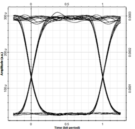
Figure 5 Eye-diagram of DWDM network with transmission distance of 80km with the EDFA and use of NRZ technique.
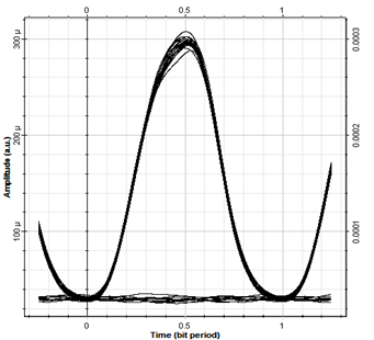
Figure 6 Eye-diagram of DWDM network with transmission distance of 80km with the EDFA and use of RZ technique.
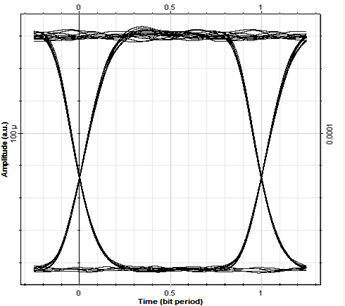
Figure 7 The Eye-diagram of DWDM network with transmission distance of 80km with the Raman amplifier and use of NRZ technique.

Figure 8 Eye-diagram of DWDM network with transmission distance of 80km with the Raman amplifier and use of RZ technique.

The Designed DWDM Network

Q-factor

With EDFA and NRZ

53.302

With EDFA and RZ

47.775

With Raman Amplifier and NRZ

68.474

With Raman Amplifier and RZ

59.506

Table 4 The Q-factor for 80km transmission distance with bit rate of and 80 Gb/s

In another design attempt, in the case of Raman amplifier included in the network, we have increased the transmission distance to 88 km in the new calculations. The resulting eye-diagrams are depicted in Figure 9 & Figure 10 for NRZ and RZ techniques, respectively. The obtained Q-factors for transmission distance of 88 km with 80 Gb/s are listed in Table 5.

Figure 9 The eye-diagram of the received signal using Raman amplifier with NRZ technique.

Figure 10 The eye-diagram of the received signal using Raman amplifier with RZ technique.

The Designed DWDM Network

Q-factor

With Raman amplifier and NRZ

53.942

With Raman amplifier and RZ

44.404

Table 5 The Q-factors for transmission distance of 88km with bit rate of 80 Gb/s

Discussion

In a study which was done by Singh and colleagues in 2013,9 a wavelength division multiplexing (WDM) system with a bit rate of 10Gb/s, the effects of Raman amplifier and EDFA with channel numbers of 16, 32, 64 was investigated, where it was shown that by increasing the dispersion from 2 to 10ps/nm.km, the system performance was better in case of Raman amplifier than EDFA.

In 2002, the reasons for advantages of using Raman amplifier were reported by Islam MN18 where it was revealed that this amplifier with higher noise figure would reduce the non-linearity effects of optical fiber, thus resulting in increase of transmission distance with higher bit rate and smaller channel spacing. In another report in the same year, a study on comparison of using two amplifiers, EDFA and Raman, by optimization of the network on using diode pumping, the advantage of Raman amplifier was proved to be superior to that of EDFA.19

In the present paper, on investigation of the effects of Raman amplifier and EDFA used in a DWDM network with NRZ and RZ encoding techniques, based on eye-diagrams and Q-factors of the received signals, it is revealed that network performance has become better while using Raman amplifier for amplification in DWDM networks.

In the received signals in each designed DWDM network, some specifications can be extracted from the resulting eye-diagrams. It is noted that the higher height opening of eye-diagrams introduces lower noise. The amplitude of each diagram shows the power of received signal, so on a comparison, we could find that a better situation in design is achieved.20

We can predict the distortion of the designed network using the eye-diagrams, as well. The more disarrayed diagram proves the presence of distortions. Availability of more information in the eye-diagrams may help designers to minimize the faults during implementation of optical networks. With respect to Q-factor, the more its value, the better will be the network performance, which is the result of higher detectable signal power than the present noise power in the receiver end.21,22

Conclusion

This paper presented an analysis of the effects of the EDFA and Raman amplifier on DWDM optical network with a bit rate of 80 Gb/s and 80km and 88km transmission distances, using Optisystem solver. On comparison of eye-diagrams of the DWDM network while using EDFA and Raman amplifier, it is shown that in the case of Raman amplifier the Q-factor is higher and the network performance is better than when the EDFA is used in the network. As well, it is revealed that when NRZ modulation scheme is used, the quality of the received signals in the receiver is better than the RZ technique.

Since the non-linearity effects in optical transmission line reduces to a minimum level while using Raman amplifier, one can design an optical network operable at longer distance. To this end, we have increased the transmission distance from 80 to 88km and kept other specifications unchanged. It is found that the employment of Raman amplifier and NRZ technique, would allow establishing a DWDM network to have the same performance quality as that of 80km network with EDFA inclusion.

Such a network would provide increase of transmission span in a long-haul optical network with reduced number of optical connectors and reduction of total loss, thus decreases the total cost of the network operation, installation, and maintenance.

Acknowledgments

None.

Conflicts of interest

Author declares there is no conflict of interest.

References

  1. Ohsono K, Nishio T, Yamazaki T. Low Non-linear Dispersion-shifted Fiber for DWDM Transmission. Hitachi Cable Review. 2000;19:45–48.
  2. Yu J, Zhou X. Ultra-High-Capacity DWDM transmission system for 100G and beyond. IEEE Communications Magazine. 200;48(3).
  3. Headley C, Agrawal GP. Raman Amplification in fiber optical communications systems. 1st edn. Academic Press, USA, 2005.  p. 4–15.
  4. Green P. Progress in optical networking. IEEE Communications Magazine. 2001;39(1):54–61.
  5. Svelto O, Longhi S, Valle GD. Lasers and Coherent Light Sources. In: Träger F editor. Springer Handbook of Lasers and Optics, Springer, Berlin, Heidelberg, Germany, 2012. p. 641–1046.
  6. Saleh BEA, Teich M. Fundamentals of Photonics. John Wiley & Sons, New Jersey, USA. 2007.
  7. Kolimbiris H. Fiber optics communications. Pearson Prentice Hall, New Jersey, USA. 2003.
  8. Agrawal GP. Applications of Nonlinear Fiber Optics. 2nd edn. Academic Press, USA. 2007.
  9. Singh S, Singh A, Kaler RS. Performance evaluation of EDFA, Raman and SOA optical amplifiers for WDM systems. Optik. 2013;124(2):95–101.
  10. https://optiwave.com/optisystem/
  11. Gumaste A, Antony T. DWDM Network Designs and Engineering Solutions. Cisco Press, Indiana, USA. 2002.
  12. Keiser G. Optical Fiber Communications. 2nd edn, Mc-Graw Hill, Pennsylvania Plaza, New York, USA. 1991.
  13. Seraji FE, Kiaee S. Eye-Diagram-Based Evaluation of RZ and NRZ Modulation Methods in a 10-Gb/s Single-Channel and a 160-Gb/s WDM Optical Networks. International Journal of Optics and Applications. 2017;7(2):31–36.
  14. Nguyen BE. Optical Fiber Communications Systems (Optics and Photonics). 2nd edn, CRC Press, USA, p. 385. 2011.
  15. Characteristics of a non-zero dispersion-shifted single-mode optical fibre and cable. Recommendation ITU-T G.655, (11/2009). International Telecommunication Union, Switzerland. 2009.
  16. A Guide for fiber optics and premises cabling. May 02 2014, www.thefoa.org/tech/ref/OSP/term.html#loss.
  17. Agalliu R, Lucki M. Benefits and Limits of Modulation Formats for Optical Communications. Optics and Optoelectronics. 2014;12(2): 160–167.
  18. Islam MN. Raman amplifier for telecomm-unications. IEEE Journal of Selected Topics in Quantum Electronics. 2002;8:848–859.
  19. Namiki S, Emori Y. Ultrabroad-band Raman amplifiers pumped and gain-equalized by wavelength-division-multiplexed high-power laser diodes. IEEE Journal of Selected Topics in Quantum Electronics. 2001;7(1).
  20. Freude W, Schmogrow R, Nebendahl B. Quality metrics for optical signals: eye diagram, Qfactor, OSNR, EVM and BER. IEEE, 2012. p. 1–4.
  21. Chan CCK. Optical Performance Monitoring: Advanced Techniques for Next-Generation Photonic Networks. Elsevier Inc, USA. 2010.
  22. Agrawal GP. Fiber-Optic Communication Systems. 4th edn, John Wiley & Sons, Hoboken, New Jersey, USA. 2010.
Creative Commons Attribution License

©2018 Seraji, et al. This is an open access article distributed under the terms of the, which permits unrestricted use, distribution, and build upon your work non-commercially.