eISSN: 2574-9927


Research Article Volume 8 Issue 1
Department of Mechanical and Manufacturing Engineering, Aalborg University, Denmark
Correspondence: Syed Talat Ali, Department of Mechanical and Manufacturing Engineering, Denmark.
Received: December 19, 2023 | Published: January 22, 2024
Citation: Ali ST, Riis A Larsen RM. Comparison of test methods for crevice corrosion propagation and repassivation potential of stainless steel AISI 316. Material Sci & Eng. 2024;8(1):9-13. DOI: 10.15406/mseij.2024.08.00229
The crevice corrosion propagation modes and repassivation potential of stainless steel AISI 316 in chloride solution were compared using cyclic potentiodynamic polarization (CPP), potentiodynamic-galvanostatic-potentiodynamic (PD-GS-PD) and Tsujikawa– Hisamatsu electrochemical (THE) methods. The PD-GS-PD method was found to be the most conservative electrochemical technique which delivered the lowest repassivation potential value in a relatively short time. The crevice corrosion propagation modes in these three electrochemical methods were also compared with crevice corrosion propagation mode in galvanically coupled small area stainless steel AISI 316 anode with large area titanium cathode. The crevice corrosion propagation mode achieved in galvanically coupled AISI 316 anode at open circuit potential simulated the crevice corrosion propagation mode in real systems. The crevice corrosion propagation modes achieved in PD-GS-PD and THE methods mimicked the crevice corrosion propagation in real systems.
Keywords: crevice corrosion, repassivation, galvanostatic, potentiodynamic polarization, potentiostaic, cyclic polarization
Type AISI 316 stainless steel is largely being used in a variety of applications requiring corrosion resistance superior to AISI 304 stainless steel. Typical uses include exhaust manifolds, furnace parts, heat exchangers, jet engine parts, pharmaceutical and photographic equipment, valve and pump trim, chemical equipment, digesters, tanks, evaporators, pulp, paper and textile processing equipment, parts exposed to marine environment and tubing.1 This type of austenitic stainless steel is susceptible to crevice corrosion. The susceptibility of stainless steel 316 to crevice corrosion depends on environmental and metallurgical variables, including chloride concentration, pH, oxygen concentration, temperature, presence of inhibitors and applied potential.2,3 Crevice corrosion is a specific type of localized corrosion that involves the creation of an occluded region at a particular site on the metal surface by a crevice former. The former can be metal or non-metal. The occluded region can then develop its own chemistry and potential distribution entirely different from the bulk solution. With time, the occluded region develops an aggressive environment in terms of solution chemistry into which metal is dissolved. After a period of time, enough mass loss is taken place to cause failure. Crevice corrosion morphology is often characterized by regions of unattacked metal near the crevice mouth followed by areas of severe penetration deeper into the crevice. This morphology is referred to as intermediate attack.4
Several theories and mathematical models have been proposed to explain the occurrence and growth of crevice corrosion in stainless steel.5–9 The critical crevice solution theory model is primarily concerned with the manner in which the occluded geometry of a crevice restricts the mass transport of species into and out of the occluded region resulting in aggressive solution chemistry in terms of pH and chloride concentration.5–7 IR drop mechanism states that crevice corrosion would abruptly start when the potential difference between the crevice mouth and interior was large enough to cause the anodic potentials to become active.8 Stewart developed a computational model that combined CCS and IR* theories to examine the effects of cathodic reactions inside crevices.9 Using this model, Lee et al. in his prior work validated a governing quadratic scaling law for crevice corrosion of nickel in sulfuric acid.10 Later on in his investigations Lee et al. results predicted that a chemistry dependent potential current behavior is the factor that controls the spatial distribution of crevice corrosion attack in the acidic chloride environments.11
The literature survey reveals that the prior work on the morphology of crevice corrosion attack has mainly focused on the initiation mechanism of crevice corrosion and determination of the location of maximum crevice attack both experimentally and computationally. As it is well known that the stainless steel is susceptible to crevice corrosion. It is therefore, extremely important to explore the electrochemical methods which can predict what happens in the real systems where crevice corrosion in stainless steel 316 can initiate, propagate and repassivate in one exposure. In last couple of decades various electrochemical methods have been proposed to measure the repassivation potential of different alloys including cyclic potentiodynamic polarisation (CPP) (ASTM G61), Tsujikawa–Hisamatsu electrochemical (THE) (ASTM G192), potentiostatic (PS), mixed potentiodynamic–potentiostatic (PD-PS-PD) and mixed potentiodynamic–galvanostatic (PD-GS-PD) methods.12–15
The main goal of this research work is to evaluate the different electrochemical methods used to investigate the crevice corrosion propagation in stainless steel 316 which mimic the crevice corrosion propagation in real systems. Among several electrochemical methods CPP, THE and PD-GS-PD methods were utilized in the present work. In the present study a galvanic-coupling technique was also employed in which a creviced stainless steel 316 working electrode was coupled to a large area titanium counter electrode through a zero resistance ammeter. This arrangement simulates the crevice corrosion process in real systems and avoids electrochemical perturbation of the system. The crevice corrosion propagation in this galvanically coupled stainless steel 316 working electrode was compared to the crevice corrosion propagation during aforementioned crevice corrosion testing methods.
The chemical composition of stainless steel AISI 316 use in this research work is given in Table 1. The The Avesta Cell manufactured by Bank Elektronik was used to carry out the crevice corrosion experiments. The crevice corrosion was created between Viton O-ring and stainless steel 316 sample by removing filter paper and without flushing deionized water around the periphery of the O-ring. The exposed area of the sample inside the Avesta cell was 1cm2 and the applied torque was 5 N-cm to avoid bending of the sample and mounting support. The stainless steel sample was wet grinded with 500 grid silicon carbide paper and then degreased in acetone and finally rinsed in deionized water and air-dried. The Gamry reference 600 potentiostat/galvanostat/ZRA was employed for all electrochemical measurements in the present research study. All crevice corrosion experiments were carried out in 3.5 wt % sodium chloride solution at 25°C. All potential values in this present work were recorded with respect to the reference saturated calomel electrode (SCE). In all experiments the open circuit potential was monitored for 1 h while purging argon through the electrolyte. After the 1 hour Argon gas treatment, a potentiodynamic anodic polarization was applied at a scan rate of 0.167 mV/s starting 100 mV below the open-circuit potential and progressed anodically until the current density of 2 μA/cm2 was achieved. For Galvanic coupling test three titanium strips of the same size (50 mm x 10 mm x 1.2 mm) were introduced in the Avesta cell to investigate the crevice corrosion while simulating the real environment. The surfaces of the creviced specimens were examined with Leica MZ6 stereomicroscope and Zeiss Axio Imager M2m microscope.
Cyclic potentiodynamic polarization (CPP)
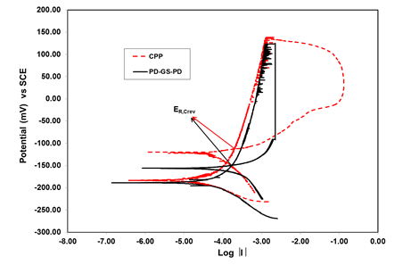
The cyclic potentiodynamic polarization is one of the tests to assess the susceptibility of stainless steel 316 to localized corrosion and repassivation potential.12 Figure 1 shows the CPP curve for stainless steel AISI 316 in 3.5 wt% NaCl solution at 25°C. The scan was started 100 mV below open circuit potential at a scan rate of 0.167 mV/s in the forward direction and the potential scan was reversed when the current density of 2 µA/cm2 was achieved. The threshold current density was adjusted at 2 μA/cm2 to prevent the specimen anodic potential from entering into the transpassive region. The corrosion potential (Ecorr) value of -183 mV vs SCE was obtained. The reverse polarization showed a delayed hysteresis, suggesting the nucleation and growth of crevice corrosion during the reverse scan. In this study, the repassivation potential is defined as the potential at which the reverse and forward scans intersect each other for the first time. The repassivation potential (ER, crev) value of -112mV vs SCE was measured. This method lasted in approximately 4 hours.
|
%C |
%Si |
%Mn |
%P |
%S |
%Cr |
%Mo |
%Ni |
%N |
|
0.07 |
1.00 |
2.00 |
0.045 |
0.015 |
16.5- 18.5 |
2.00- 2.50 |
10.0- 13.0 |
0.10 |
Table 1 Chemical composition of stainless steel AISI 316
Potentiodynamic - Galvanostatic - Potentiodynamic (PD-GS-PD)
The potentiodynamic-galvanostatic-potentiodynamic is also one of the tests like CPP to assess the susceptibility of stainless steel 316 to localized corrosion and repassivation potential.15 Figure 1 depicts the curve for PD-GS-PD method. In PD-GS-PD method the potential was first scanned in the anodic direction at a rate of 0.167 mV/s starting at 100 mV below Ecorr When the current reached a predetermined value, a nominal current density of 2 μA/cm2, the control mode was switched from potentiodynamic to galvanostatic and the current was maintained for 2 hours. This second part of the experiment allowed the localized corrosion to propagate and the potential was recorded. After the 2 hours constant current step, the control mode was switched to potentiodynamic scan in the reverse direction. The PD-GS-PD method differs from CPP method in that sense that it has intermediate stage of galvanostatic stage between forward and reverse scans. The recorded values of corrosion potential (Ecorr) and the repassivation potential (ER, crev) during PD-GS-PD method were found to be -189 mV vs SCE and -149 mV vs. SCE respectively.

Figure 1 CPP and PD-GS-PD methods to determine repassivation potential of stainless steel AISI 316 in 3.5 wt% NaCl at 25 C.
This method consumed approximately 4 hours to complete all the steps.
Tsujikawa–Hisamatsu electrochemical (THE)
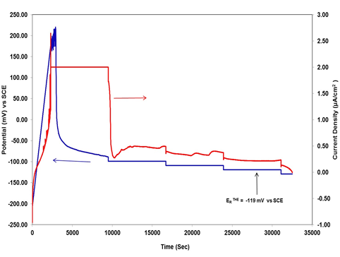
Figure 2 illustrates the Tsujikawa–Hisamatsu Electrochemical (THE)13 technique to determine the repassivation potential of stainless steel 316 in 3.5 wt% NaCl solution at 25°C. In this technique potentiodynamic scan also started in the anodic direction at a rate of 0.167 mV/s. The potentiodynamic scan was stopped when the measured current density reached up to 2 μA/cm2 then this current was held galvanostatically for 2 h to propagate the crevice corrosion. The potential achieved after this period was taken as a starting point for the following potentiostatic stage in which the potential was controlled for 2 hours periods at values decreasing by 10 mV for each step. until crevice corrosion repassivation ERTHE value of -119 mV vs SCE was achieved. ERTHE was determined as the highest potential at which the current density decreased as a function of time during the 2 hours step and no further increase in current density was observed at lower potentials ERTHE. Usually this technique requires approximately 24 hours for its completion.

Figure 2 Tsujikawa–Hisamatsu Electrochemical (THE) methods to determine repassivation potential of stainless steel AISI 316 in 3.5 wt%.
Galvanically coupled experiment
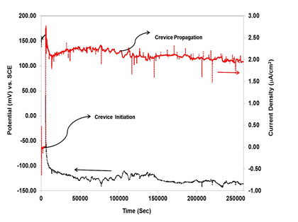
This technique is designed to simulate the small area anode – large area cathode typical in crevice corrosion situations, and to allow measurement of the crevice propagation rate as a function of time. This technique of creating crevice corrosion situation avoids electrochemical perturbation of the system. In the present work the crevice corrosion on small stainless steel anode sample was created by coupling with large area titanium strips as a cathode. Normally the stainless steel and titanium are very close in galvanic series, therefore the contribution due to the titanium on the corrosion of a stainless steel sample of similar size is negligible. However, if the area of the titanium cathode largely exceeds the area of the stainless steel anode then such a contribution can become significant.16 Figure 4 shows crevice corrosion current (IC) and crevice potential (EC) measured in a galvanically-coupled stainless steel-titanium experiment. After 5600 seconds the crevice corrosion was initiated and the crevice corrosion current (IC) of stainless steel-titanium couple abruptly jumped to 2.5 uA/cm2 and the galvanic corrosion potential (Ec) of the stainless steel- titanium dropped from 160 mV vs SCE to -100 mV vs SCE which is very clear indication of initiation of crevice corrosion on stainless steel sample. In the next stage the crevice corrosion was propagated for further 254400 seconds while simulating the real environment.
Comparison of crevice corrosion test methods
In the present work three routine methods (CPP, PD-GS-PD, THE) was employed to examine the crevice corrosion propagation and repassivation potential of stainless steel 316. In aforementioned three electrochemical methods, three different stages may be clearly differentiated: induction (stage 1), propagation (stage 2) and repassivation of crevice corrosion (stage 3). Stage 1 is nearly same for all the methods which includes potentiodynamic scan until a predetermined potential or current density value is achieved.
Stage 2 consists of crevice corrosion propagation at a fixed current density (THE and PDGS-PD). In the CPP method, the propagation stage is not clearly distinguished, and the propagation occurs partially during the forward and reverse scans. The THE and PD-GSPD methods limit the amount of crevice corrosion propagation by holding the same current density during the galvanostatic stage for 2 hours. In contrast CPP method does not control the amount of propagation and current density, even though the hold current density and potential is predetermined. Stage 3 involves the potentiodynamic scan in the reverse (cathodic) direction (CPP and PD-GS-PD) or in steps (THE). The PD-GS-PD and THE methods only vary in the repassivation stage.
Figure 2 illustrates that the most useful information regarding corrosion potential and repassivation potential can be extracted from the curves for CPP and PD-GS-PD methods. Additional information of breakdown potential can be achieved with CPP method by extending the range of anodic potential and current density. As mentioned earlier in the present work, the current density and potential for CPP method was adjusted at a value to prevent the specimen anodic potential from entering into the transpassive region. The CPP and the PD-GS-PD methods deliver the information about susceptibility of stainless steel 316 to localized corrosion under a given environment after 4 hours of testing. In contrast Tsujikawa-Hisamatsu Electrochemical (THE) method only offers the value of repassivation potential after 16-20 hours of testing in case of stainless steel 316. The repassivation potential values recorded for the three methods indicate that the PD-GS-PD method offers the lowest value -149 mV vs SCE of repassivation potential (ER,Crev) under the given environment. In contrast CPP method provides the highest value -112 mV vs SCE of repassivation potential (ER, Crev) under the same environment. The experiments were repeated 8-10 times to validate the data in this regard.14,15 have also reported in their findings that the PD-GS-PD technique provides a more conservative value of (ER,Crev) in comparison to the other two crevice corrosion testing methods.
The potentiostaic experiments were also conducted to verify the repassivation potential determine by CPP and PD-GS-PD methods as shown in Figure 3. No crevice corrosion was observed while running the potentiostatic experiments at repassivation potential values of -112m V vs SCE and -149 mV vs SCE. For 24 hours. Figure 3 depicts, although no anodic current is flowing in 24 hours experiment but the gradual increase in current towards positive (anodic ) side can be observed by holding the potential at -112 mV vs SCE . By holding the potential at -149 mV vs SCE the continuous decline in the current toward more negative (cathodic) side can be seen. It means the crevice corrosion may be expected during more long term testing at -112 mV vs SCE repassivation potential value. Therefore, the repassivation potential value determined by PD-GD-PD method can be considered more conservative and reliable.

Figure 4 Crevice current (Ic) and crevice potential (Ec) measured on a creviced stainless steel electrode galvanically coupled to a large area titanium counter electrode via a zero resistance ammeter.
Comparison of the crevice corrosion propagation as function of test method versus galvanically coupled experiment
Another main aim of this study was to evaluate the electrochemical methods which mimicked the crevice corrosion propagation in real systems. The crevice corrosion on stainless steel sample in 3.5 wt% NaCl solution at 25°C. was initiated and propagated during the three electrochemical test methods. Later on the crevice corrosion propagation mode was compared with the crevice corrosion propagation mode in galvanically coupled experiment. Figure 5(a) represents the crevice corrosion propagation during the CPP method and magnified image of the crevice region is shown in Figure 5(b). During CPP method most of the localized corrosion attack occurred outside the O-ring area which was employed as a crevice former on stainless steel 316 sample. The crevice corrosion started at the Oring metal interface, but then progressed in a massive way towards the outside of the O-ring metal interface in a uncontrolled way due to sudden increase in the current just before the reversal of the backward scan. In contrast when using PD-GS-PD and THE methods, the specimen suffered with crevice corrosion under the O-ring acted as a crevice former as depicted in Figure 6(a) and Figure 7(a) respectively. The localized crevice corrosion attack started at the O-ring metal interface and progressed underneath the O-ring. The galvanostatic step in PD-GS-PD and THE methods was responsible for initiation and propagation of the crevice corrosion in a controlled way underneath the O-ring. The magnified optical micrographs of the crevice corrosion growth mode in PD-GS-PD and THE methods are shown in Figure 6(b) and Figure 7(b) respectively.
The crevice corrosion growth was also analyzed in galvanically coupled stainless steel 316 sample. The localized crevice corrosion attack also initiated at the O-ring metal interface under open circuit conditions and progressed horizontally below the O-ring as illustrated in Figure 8(a) and Figure 8(b). The crevice corrosion propagation mode in galvanically coupled 316 sample was very much similar to the propagation modes of crevice corrosion while using PD-GS-PD and THE test methods.
The author would like to thank EUDP for financial support of BOP- Op project and all involved project partners.
There is no conflict of interest.

©2024 Ali, et al. This is an open access article distributed under the terms of the, which permits unrestricted use, distribution, and build upon your work non-commercially.