In this section, working principle and applications of some individual concentrator will be discussed. These are as follows:
Parabolic disk concentrator
If a parabola rotates about its optical axis, it gives the shape of parabolic disk concentration. It is also referred as paraboloidal disk concentrator. The receiver is placed at focal point of parabola with high concentration ratio as shown in Figure 1. Beam radiation falling on inner surface of disk is reflected at focus with finite image. It is a two-axis tracking device. The working fluid in the receiver is heated to high temperatures of about 750-1000°C. The heated fluid is then used to generate electricity by small Stirling Engine or Brayton cycle engine. The engine is attached to the receiver. Parabolic dish systems are the most efficient as compared to the other solar thermal technologies. These types of concentrators are also used for cooking. One such type of solar cooker was installed at Shirdi Sai baba temple Shirdi, Maharashtra, India.1 This system has been able to cater to the food requirements (3 course meal) of 30,000 people. In this case, the food is cooked with the help of solar energy thus saving a large amount of energy which is drawn from fossil fuels. It causes no harm to the environment and ensures that there is no impact on the global climate. So, we can protect the environment and reduce the climate change which is affecting the planet earth. The concentration ratio (C) with two-way tracking system for point focusing is given by
……………….. (1)
Where,
: Aperture Area (m2)
: Receiver Area (m2)
: Half Acceptance Angle
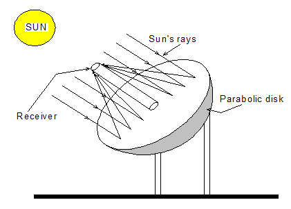
Figure 1 View of parabolic disk concentrator
The geometrical concentration ratio for cavity window receiver has been found to be nearly 9000, Li et al.,2. The thermal losses in a parabolic disk concentrator are primarily radiative heat losses which can be reduced by decreasing the absorber receiver area. The optimum intercept factor is about 0.95-0.98. The larger must be the absorber size to achieve the optimum beam intercept. The high collection efficiency with a high quality thermal energy is the basic feature of a parabolic disk concentrator operating at very high temperature for power generation. The same design can also be used for pressurized cooking. Following Mawire et al.,3 the expression for the rate of thermal energy (
) and exergy output can be written as
……………….. (2)
And
……………….. (3)
Where,
: Optical Efficiency
: Aperture Area (m2)
: Heat Loss Coefficient from Receiver to Ambient (W/m2K)
: Receiver Area (m2)
The exergy input can be expressed as
……………….. (4)
Where,
: Beam Radiation (W/m2)
: Temperature of Sun
The optical (
), thermal (
) and exergy (
) efficiency is defined as follows:
……………….. (5)
……………….. (6)
And
……………….. (7)
Where,
: Optical Efficiency
: Beam Radiation (W/m2)
: Aperture Area (m2)
: Intercept Factor
: Absorptivity
: Number of Tubes
It is important to mention that the optical instantaneous efficiency is always higher than thermal instantaneous efficiency (
). The optical, thermal and energy efficiency of disk concentrator are 52%, 40% and 8 % respectively for cylindrical cavity receiver.
Huang et al.,4 have shown that the optical efficiency of sphere receiver (
) varies between 82 to 88%. The intercept factor (
) in ideal case is 1 without optical error otherwise it is less than 1. The (
) is the product of absorptivity of receiver and transitivity of the glazed material.
Zanganeh et al.,5 studied the design of a solar parabolic dish concentrator with polyester membrane facets with small vacuum beneath the membranes. They have used Monte Carlo ray-tracing method and determined the concentration of 8000× at 90% interception factor. Mao et al.,6 & Li et al.,7 studied the solar flux and temperature distribution at receiver for the generation of power. Reddy et al.,8,9 studied the heat loss from receiver and techno-economic viability analysis of 5 MW stand-alone power plants for Indian climatic conditions of solar parabolic dish concentrator. Further, a 500 m2 paraboloidal dish solar concentrator was designed by Lovegrove et al.,10 for the generation of power.
Hyperboloid solar concentrator
The shape of hyperboloid solar concentrator can be produced by rotating the two hyperbolic (sections, AB and A1B1) design along its symmetrical axis as shown in Figure 2. The diameters of the entrance and exit aperture are referred as D1 and D2 and inner surface is reflecting one. The beam radiation incident AA1 will be reflected back and focused to the exit aperture BB1. It is a compact hyperboloid solar concentrator and only truncated version of the concentrator is used. For effective application, lenses at the entrance diameter AA1 are used. Generally, it is mainly used as a secondary concentrator for power production. Saleh et al.,11 evaluated the optical performance of a static 3-D elliptical hyperboloid concentrator (EHC) by using ray tracing method. It has a concentration ratio (CR) which can be expressed as below
CR= 20×, variation of solar incidence angles along receiver major axis
The effective concentration ratio (
) is therefore given as:
……………….. (8)
: Optical Efficiency
Where, an optical efficiency (
) was found to be 27% for concentrator height of 0.4 m and the acceptance angle of ±30°. Imhamed et al.,12 designed a 3-D elliptical hyperboloid concentrator and experimentally analyzed the system for process heat applications and power generation.
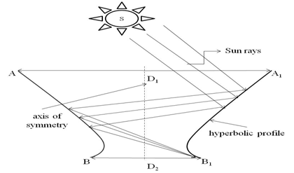
Figure 2 Structure showing a hyperboloid solar concentrator.
Fresnel lens solar concentrator (FLSC)
A Fresnel lenses solar concentrator (FLSC) consists of one side plane and other side Fresnel lenses. The plane side faces all the parallel beam radiation falling on it and Fresnel lenses side to face photovoltaic cells placed at focal point as shown in Figure 3. It is originally being developed for concentrating photovoltaic (CPV) application for power generation. A linear groove is created on one side of the refracting material. The groove angles are chosen with reference to a particular wavelength of incident beam radiation so that the lens acts as a converging for normal incidence beam radiation. The solar thermal power plant based on linear Fresnel lens reflectors of 125 MW has been installed in Dhursar, India (Table 1). The most preferable material for the construction of Fresnel lenses solar concentrator (FLSC) is plastic which is economical and easy to manufacture. The plastic Fresnel lenses with 20 grooves per mm have been molded. The grooves can also be made for surface facing beam radiation with more reflection losses and more problem of cleaning the top surface. This resulted in low thermal efficiency. There can be either focal point or line focal or flat surface as per requirement. In this case, there is a need to track the sun for maximum beam radiation and hence maximum output. Nishioka et al.,19 studied the sandblasting durability of acrylic and glass Fresnel lenses for concentrator photovoltaic modules and observed that the durability of glass Fresnel lens was approximately doubled. The design, analysis of spectrum distribution, optical performance and characterization of Fresnel lenses concentrators has been carried out.20-23 They have also optimized the design of hybrid Fresnel-based concentrator for generating uniformity irradiance with the broad solar spectrum as shown in Figure 4. Lewandowski et al., 24 carried out an assessment of linear Fresnel lens concentrators for thermal applications. Xie et al.,25 reviewed the work carried out on concentrated solar energy thermal applications by using Fresnel lenses.The design of a non-imaging Fresnel lens and reflector solar concentrators have also been studied by Leutz et al.,26 & Lainé27. Chemisana et al.,28 designed and studied optical performance of a non-imaging linear Fresnel transmissive concentrator for building integration and found that the overall global optical efficiency was 56.38%. The comparative performance of linear Fresnel concentrators for building integrated with and without photovoltaic was done by Chemisana et al.,29,30 Later on, Wu et al.,31 conducted an extensive experiment for a point focus Fresnel lens PV Concentrator (FPVC) system. An indoor experiment was performed to investigate a point focus Fresnel lens PV concentrators (FPVC) with a concentration ratio of 100X. It was observed that under natural convection when the ambient temperature (Ta) was 50°C and solar intensity 1000W/m2, the solar cell efficiency (ƞc) decreases to 7.95% and when the Ta was 20°C the ƞc was found to be 10%. Zhuang et al.,32 have considered the following equation for optical axial symmetry.
|
S. No
|
Type of Concentrators
|
Capacity
|
Manufacturer
|
Location where Plants have been Installed
|
|
1
|
Central heliostat tower receiver
|
50MW
|
Luz
|
Dagget, California13
|
|
2
|
Central heliostat tower receiver
|
110MW
|
Abengoa Solar
|
Chile14
|
|
3
|
Central heliostat tower receiver
|
50MW
|
SUPCON Solar
|
Delingha, China15
|
|
4
|
Central heliostat tower receiver
|
37MW
|
Ivanpah Solar Electric Generating System (ISEGS)
|
Primm NV, California15
|
| |
|
|
|
|
|
5
|
Central heliostat tower receiver
|
50MW
|
Abengoa Solar - IDC
|
Upington, Northern cape, South Africa15
|
|
6
|
Parabolic trough concentrator
|
50MW
|
Corporate Ispat Alloys Ltd
|
Phalodi, Rajasthan, India16
|
|
7
|
Linear Fresnel reflector
|
Two 125 MW power plants
|
Rajasthan Sun Technique Energy and Reliance Power Ltd.
|
Dhursar, Rajasthan, India17
|
|
8
|
Parabolic trough
|
100MW
|
Abengoa Solar - IDC
|
Poffader, Northern Cape, South14 Africa
|
|
9
|
Parabolic trough
|
50MW
|
Godawari Power Ispat Limited
|
Nokh, Rajasthan, India16
|
|
10
|
Parabolic Trough
|
50MW
|
ACS - COBRA group
|
Talarrubias, Badajoz, Spain16
|
|
11
|
Parabolic Trough
|
50MW
|
Elecnor/Aries/ABM AMRO
|
Olivenza, Badajoz, Spain16
|
|
12
|
Parabolic Trough
|
50MW
|
Megha Engineering and Infrastructure
|
Megha, Andhra Pradesh, India16
|
|
13
|
Parabolic Trough
|
50MW
|
Helios II HYPERION Energy Investments, S.L.
|
Ciudad Real, Puerto Lápice, Spain16
|
|
14
|
Parabolic Trough
|
50MW
|
FCC Energy
|
Palma del Río, Córdoba, Spain16
|
|
15
|
Parabolic Trough
|
50MW
|
FCC Energy
|
Villena, Alicante, Spain16
|
|
16
|
Central heliostat tower receiver
|
110MW
|
Crescent Dunes Solar Energy Project (Tonopah)
|
Tonopah, Nevada, United States16
|
|
17
|
Parabolic Trough
|
250 MW
|
Genesis Solar, LLC
|
Blythe, California, United States18
|
|
18
|
Parabolic Trough
|
50MW
|
Ferrostaal AG
|
Aldiere, Granada, Spain16
|
|
19
|
Parabolic Trough
|
50MW
|
Next Era, FPL
|
Navalvillar de Pela, Badajoz, Spain16
|
|
20
|
Parabolic Trough
|
50MW
|
Abengoa Solar
|
Sevilla, Spain15
|
|
21
|
Parabolic trough
|
50MW
|
RREF/OHL
|
Morón de la Frontera, Sevilla, Spain16
|
|
22
|
Parabolic trough
|
50MW
|
Ortiz/TSK/Magtel
|
Posadas, Córdoba, Spain16
|
|
23
|
Parabolic trough
|
50MW
|
Elecnor/Aries/ABM AMRO
|
Alcázar de San Juan, Spain16
|
|
24
|
Parabolic trough
|
50MW
|
Abengoa Solar - IDC
|
San José del Valle, Cádiz, Spain16
|
|
25
|
Parabolic trough
|
100MW
|
Abengoa Solar - IDC
|
Poffader, Northern Cape, South Africa16
|
|
26
|
Parabolic trough
|
100MW
|
Iberdrola Renovables Castilla-La Mancha
|
Puertollano, Castilla-La Mancha, Spain16
|
|
27
|
Parabolic trough
|
100MW
|
Masdar/Total/Abengoa Solar
|
Madinat Zayed, 120 km southwest of Abu Dhabi, United Arab Emirates16
|
|
28
|
Parabolic trough
|
50MW
|
Abengoa (100%)
|
Logrosán, Cáceres, Spain16
|
Table 1 Some of recent working solar thermal power concentrator plant of capacity 50MW and above all around the world
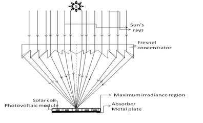
Figure 3 Sketch showing a point focus Fresnel lens concentrator.
……………….. (9)
Where θc is the half acceptance angle and C is the geometrical CR, defined as
……………….. (10)
Where,
: Aperture Area (m2)
: Receiver Area (m2)
Since the apparent angular extent of the sun is ±0.2671o, therefore, the solar concentration limit of the hybrid Fresnel-based concentrator is 46,050 ×, and geometrical CR is about 1759.8× by Eq. (10). Thus, the HCPV system is obtained (CR>300). Larsen et al.,33 investigated the heat loss in a linear absorber with a trapezoidal cavity of Fresnel reflecting solar concentrator under simulated condition. They observed that heat loss is predominant by radiation of the bottom transparent window due to high operating temperature of for 110°C< Tpipe < 285°C. Further, it was reported that heat loss coefficient varied in the range between 3.39 to 6.35 W/m2 K. After the distribution of solar flux at PV module as shown in Figure 4 the electrical efficiency will increase due to low operating range in comparison to point focus Fresnel lens. Moreover, electrical efficiency can be increased if the back side of PV module is further cooled by flowing of either water/air (Figure 5 ) (Figure 6).
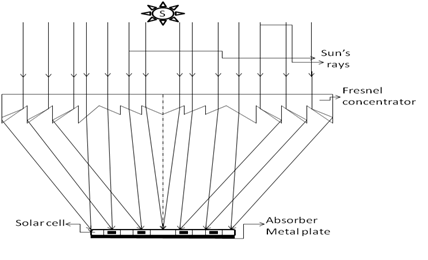
Figure 4 Schematic view of focal plane Fresnel lens concentrator.
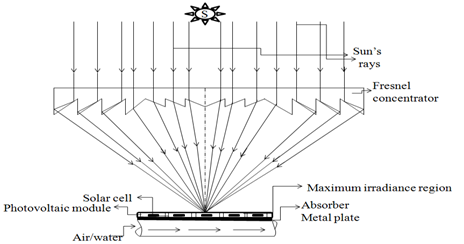
Figure 5 Sketch showing point focus Fresnel lens concentrator with working fluid flowing below the absorber plate.
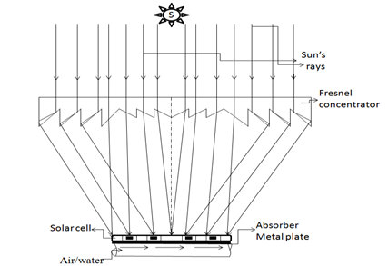
Figure 6 Sketch showing a focal plane Fresnel lens concentrator with working fluid flowing.
Compound parabolic concentrator (CPC)
Conventional compound parabolic concentrator (CPC): It consists of rotated parabolic sections which reflect all incident beam radiation to the aperture down to the receiver as shown in Figure 7. This CPC is a non-imaging concentrator with a highest possible concentration ratio (1/sin (θa) where θa is one-half of the angle permissible by thermodynamic limit for a given acceptance angle, θa. Further, it has a large acceptance angle and it needs to be intermittently turned towards the sun. A compound parabolic concentrator (CPC) was initially designed by Winston34 & Baranov35 It consists of two parabolic segments which are oriented such that the focus of one is located at the bottom end point of the other one and vice-versa. The axes of the parabolic segments subtend an angle with beam radiation which is equal to acceptance angle. The slope of the reflector surfaces at the aperture plane is parallel to the CPC axis. The receiver is a flat surface parallel to the aperture joining two foci of the reflecting surfaces.
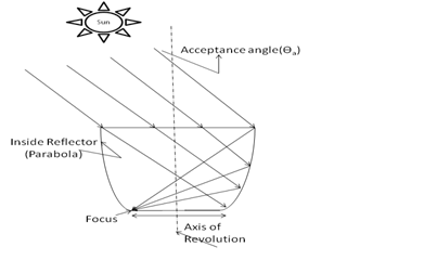
Figure 7 View of a compound parabolic concentrator.
Rabl36 found that the number of reflections depends on the incident angle, collector depth and concentration ratio. The cost of a unit can be decreased by truncating the CPC to half in height without any significant change in concentration.
……………….. (11)
Where,
: Half Acceptance Angle
The compound parabolic concentrator (CPC) is simple in design and modelling and hence has many applications. The thermal performance of a box-type solar cooker integrated with an asymmetric CPC by using Figure 1 & Figure 2 of merit was studied by Harmim et al.,37 The proposed box type solar cooker remains in a stationary position during its testing which can be integrated into building facade. The design, performance, modelling, experimental validation, heat losses, normal/inverted absorber, asymmetric/symmetric of compound parabolic concentrators for air/water heating systems have been studied by many authors.38-40
In order to increase the performance of compound parabolic concentrators (CPC), many parametric studies were carried out by many researchers.4-46 which includes
- Fully illuminated inverted V wedge absorbers
- Reduction of heat losses
- The minimal reflector surface
- Air cavity below absorber etc
- The lowest angular acceptance
- Minimum number of reflections
Tiba et al.,47 reported that an annual thermal energy by the CPC, at 80°C is 35% greater than for flat collector with increased reflectivity of the CPC to 0.96 from 55%. Many authors.48-50 studied the water purification technology by using an inverted absorber solar still (IASS). In this case, solar radiation is reflected back to bottom of solar still by compound either parabolic concentrator or cylindrical reflector. The results were also compared with conventional single slope solar still (SS) by using the concept of characteristic equation. It has been observed that inverted absorber solar still is better. An asymmetric compound parabolic photovoltaic concentrator (ACPPVC) of geometrical concentration ratio 2 was designed and developed by Mallick et al.,51 which can be used for building facade integration. It was observed that the maximum electrical output power was about 62% more in comparison with non-concentrating collector with 3.4% electrical power and 15% optical losses.
Photovoltaic thermal compound parabolic concentrator (PVT-CPC): A PVT-CPC system is basically consisting of integration of a photovoltaic thermal system and a compound parabolic concentrator system. Guiqiang et al.,52 & Mallick et al.,53 studied the electrical and thermal performance of photovoltaic thermal compound parabolic concentrator by using water and air as a working fluid. The hot water/air can be used to heat the room of a building as per requirement. The water and air channel is placed below the PV module at bottom of CPC. They observed that the electrical efficiency of PV module is increased with an enhanced electrical power. A small dielectric photovoltaic thermal compound parabolic concentrator (dCPC) for the day lighting of the building was developed by Yu et al.,54 The truncated bottom of dCPC can also be used with PV module to produce electricity. Guiqiang et al.,55 & Su et al.,56]proposed a concept of lens-walled compound parabolic concentrator (CPC). They observed that new lens wall CPC has larger half acceptance angle with more uniform flux distribution than mirror CPC with the same geometrical concentration ratio of 4X. The lens-walled CPC has a better annual solar collection performance than the corresponding mirror CPC. Further, Guiqiang et al.,57 studied the structure of the lens-walled CPC with air gap and found that there is an increase of optical efficiency of 10% due to total internal reflection. Figure 8 illustrates side view of a partially covered photovoltaic thermal compound parabolic concentrator (PVT-CPC). The beam radiation from the sun falls on aperture area (Aa) from where it gets reflected from reflector and descends to the receiver/absorber plate. The receiver of area Ar is half covered with a semitransparent photovoltaic module and the other half is glazed. The water temperature at the outlet of semitransparent PV module covered collector becomes the inlet water temperature of glazed covered flat plate collector. The beam radiation is transferred from the non-packing area of PV module and it gets absorbed by the receiver/absorber plate. Thermal energy from the PV module is transferred to the plate (Figure 9). This leads to an increase in the temperature of absorber plate which further increases the temperature of water. The final outlet temperature from the partially covered PVT-CPC system is. In a PVT-CPC system following cases were analyzed by Atheaya et al.,58
- Case (i) partially covered PVT-CPC system (The absorber plate is half covered with solar cells and another half is covered with glass).
- Case (ii) fully covered PVT-CPC system (The absorber plate is covered completely by solar cells).
- Case (iii) conventional CPC system (The absorber plate is covered with glass).
- Case (iv) partially covered PVT system (The absorber plate is half covered with solar cells and another half is covered by glass; CPC is absent in this case).
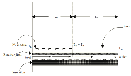
Figure 8 Sectional side view sketch of partially covered PVT-CPC system.
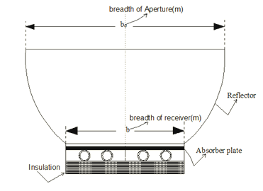
Figure 9 Front view sketch of a partially covered PVT-CPC system.
The basic energy balance equation of the PVT-CPC system is as follows:
Lower portion of the PVT-CPC system
For semi-transparent photovoltaic (PV) module
……………….. (12)
For blackened tube in plate type absorber
……………….. (13)
For flowing fluid below the absorber
……………….. (14)
Now, the energy balance of conventional CPC collector and flowing fluid can be written as follows:
Absorber
……………….. (15)
Flowing fluid
……………….. (16)
Following Tiwari et al. [59], the rate of thermal energy available from the PVT-CPC water collector is given as
……………….. (17)
Where,
And
An instantaneous thermal efficiency generally known as characteristic equation of PVT-CPC water collector can be obtained as
……………….. (18)
Where,
: Density
:Beam Radiation (W/m2)
: Heat Loss Coefficient from Receiver to Ambient (W/m2K)
: Penalty Factor Due To Absorber/Receiver Plate
: Penalty Factor Due to Glass Cover for the Portion Covered By Glazing
: Specific heat of fluid (J/kgK)
: Receiver Area Covered by PV Module (m2)
: Product of Effective Absorptivity and Transitivity
The numerical values of
and
in Eq. (18) for all cases considered are given in Table 2. The characteristics curve for all the cases are given in Figure 10 & Atheaya et al.,58 It can be seen from the Figure 10;58 that the instantaneous thermal efficiency of conventional CPC collector system is maximum because of high thermal gain as compared to other cases. Moreover, the thermal efficiency gain for partially covered PVT-CPC has been less than the partially covered PVT water collector system because of high temperatures. The thermal efficiency gain for fully covered PVT-CPC system was least as compared to all the systems because of high thermal losses.
Cases |
System Description |

|

|
Case (i) |
Partially covered PVT-CPC system |
0.7187 |
4.6222 |
Case (ii) |
Fully covered PVT –CPC system |
0.368 |
5.4126 |
Case(iii) |
Conventional CPC water collector |
0.9848 |
3.7078 |
Case (iv) |
Partially covered PVT water collector |
0.4947 |
4.2769 |
Table 2 Values of (AFR (ατ)1 and (AFRUL)1 for different cases of PVT-CPC system, Case (i), Case (ii), Case (iii) and case (iv)
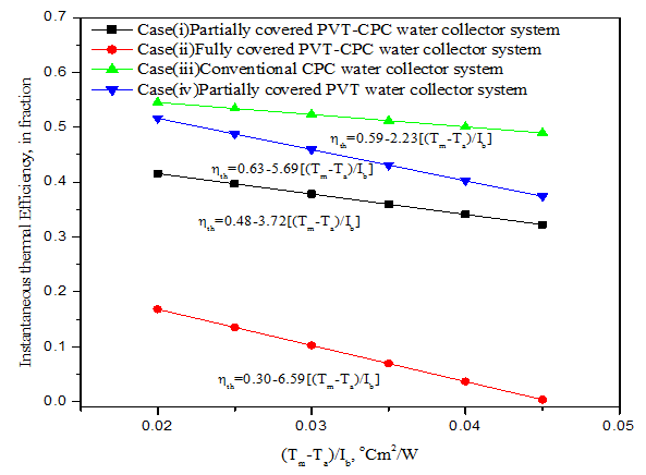
Figure 10 Graph showing a characteristic curve of partially covered PVT-CPC water collector system[Case(i)], fully covered PVT-CPC water collector system[Case(ii)], conventional CPC water collector system[Case (iii)] and partially covered PVT water collector system[Case (iv)].58
Inverted absorber PVT-CPC system: Recently, Atheaya et al.,60 (Figure 11) have done a comparison study of inverted absorber PVT-CPC system with a normal PVT-CPC system (excluding inverted absorber). They have reported that an IAPVT-CPC system is cost effective.
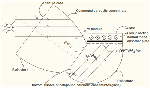
Figure 11 Side view of inverted absorber partially covered PVT-CPC system.60
Cylindrical parabolic solar concentrator
A cylindrical parabolic trough concentrator is an optical imaging device. It consists of a cylindrical parabolic reflector with anodized aluminium sheet and a metal tube receiver placed at focal point as shown in Figure 12 & 13, Anon62 The cylindrical receiver is blackened and glazed with co-axial glass tube which can be rotated about one axis to track the sun's diurnal motion. The heat transfer fluid flows through the receiver for thermal heating. The space between the receiver and glass tube is evacuated to minimize convective heat loss. The concentration ratio for a cylindrical absorber varies from 5 to 30.

Figure 12 Sketch of a cylindrical parabolic trough concentrator.
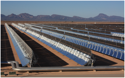
Figure 13 Photograph of a cylindrical parabolic trough concentrator.61
……………….. (19)
Where
……………….. (20)
Where,
: Beam Radiation (W/m2)
: Aperture Area (m2)
: Receiver Area (m2)
: Optical Efficiency
: Flow Rate Factor, Dimensionless
: Heat Loss Coefficient from Receiver to Ambient (W/m2K)
: Reflectivity
: Intercept Factor
: Product of Effective Absorptivity and Transitivity
: Half Acceptance Angle
Ouagued et al.,63 presented a mathematical model for parabolic trough collector to determine the working fluid temperature, heat gain and heat loss from absorber. The performance has been evaluated for different heat transfer fluid (HTF) for the Algerian climatic condition by them. They noted that heat gain decreases with operating temperature due to more heat losses as expected. The effect of a sphere receiver in the parabolic reflector has been studied by Huan64 They found that sphere receiver has higher efficiency than solar tower and parabolic trough due to less heat loss and higher cosine factor. Recently, a heat transfer analysis has been carried out by Padilla65 for a cylindrical absorber of parabolic trough collector. They observed that the heat loss increases with increase of working fluid temperature as expected. Conrado et al.,66 presented the three dimensional dynamic model for parabolic trough collector with water displacement. List of some of the recent working solar thermal power plants using parabolic trough technology is given in Table 1.
Dielectric totally internally reflecting concentrator (DTIRC)
Dielectric totally internally reflecting concentrator (DTIRC) works on principle of total internal reflection (TIR) properties of the dielectric medium. A DTIRC consists of three parts namely the front curved surface, the totally internally reflecting sidewall (profile) and the exit aperture. The Figure 14 shows the cross-sectional view of dielectric totally internally reflecting concentrator (DTIRC). In this case, a set of beam radiation incident on the front curved surface at the extreme angle. Each beam radiation is refracted through the front curved surface. Further, it is totally internally reflected from the sidewall (S1-S3) and eventually hits the exit aperture (S3-S4). In general, the side profile (S1-S3) is divided into two parts as:
- The portion from S1 to S2 and
- The portion from S2 to S3.
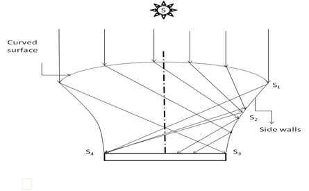
Figure 14 Sketch of a dielectric totally internally reflecting concentrator (DTIRC).
All beam radiation (extreme rays) between S1 and S2 are directed to the corner S4 after a single total internal reflection (TIR). The beam ray hitting S2 just satisfies total internal reflection (TIR) and exits from S4 beam rays between S2 and S3, the refractive index is not high enough to totally reflect the extreme rays to S3.
A mirror symmetrical dielectric totally internally reflecting concentrator (MSDTIRC) integrated PV system was developed by Muhammad et al.,67,68 Its electrical and optical performances were also investigated for building integrated photovoltaic applications. Their aims were to providing sufficient gain to increase the electrical output of photovoltaic (PV) system and to reduce the size of the PV module for cost effectiveness of system. The MSDTIRC-PV structure is capable of providing a maximum power concentration of 4.2 when compared to a similar PV module without the concentrator.
Flat high concentration devices (FHCD), Minano et al.,69
In this case, refraction, reflection and total internal reflection take place. The incident beam radiation is first refracted from the top surface and then reflected towards top. After reflection, there is a total internal reflection of beam radiation towards solar cell. There is also a front mirror opposite to the solar cell.
Quantum dot solar concentrator
A quantum dot is a nano crystal. It is made up of semiconductor materials. It is very small and exhibits quantum mechanical properties. The excitations of quantum dots are confined in all three spatial dimensions. The electronic properties of these materials are in between bulk semiconductors and discrete molecules. It increases the efficiency of the solar cell.
The quantum dot solar concentrator has been illustrated in Figure 15. (QDSC) is a novel non-tracking solar concentrator. It consists of three parts namely
- A transparent sheet of glass/plastic comprising seeded quantum dots (QDs) in materials
- Reflecting mirrors on three edges/sides and
- An attached solar cell to exit. In this case, both direct and diffuse solar energy are concentrated on attached photovoltaic cells.
The advantages of solar concentrator over conventional flat plate collectors are as follows:
- It increases the solar intensity at a smaller absorber (receiver) area
- The heat-loss area is reduced.
- The delivery temperature is very high.
- It helps in reducing the cost of absorber/receiver
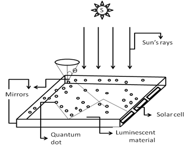
Figure 15 View of a quantum dot concentrator.
However, solar concentrator is an optical system and hence the optical losses become important.
Gallagher et al., 70 observed that the system achieved higher concentration factors between 3.78 and 8.65 for polyurethane sample (without QDs) cast in an unmirrored perspex mould. The PV cell was orientated as in a QDSC. The highest fill factor of 0.7 was achieved in a QDSC of 0.08% volume fraction of CdSe/CdS F2 QD. The maximum electrical efficiency was observed to be between 3-3.5%. Chandra et al.,71 found that the plasmonic excitation enhanced fluorescence of CdSe/ZnS core-shell quantum dots (QDs) in the presence of Au nano particles (NPs) in quantum dot solar concentrator (QDSC) devices. There is a maximum 53% fluorescence emission enhancement for optimum QD/Au NP composite. The electrical conversion efficiency of CdSe core/multishell quantum dots for luminescent solar concentrators found by Bomm et al.,72 was 2.8% with 45% quantum yields. A concept of quantum dot containing coatings on glass panes for photo luminescent solar concentrators has been proposed by Schüler et al.,73 It has been recommended that there is a high potential for low-cost fabrication on the large scale and the suitability for architectural integration. Kennedy et al.,74 reported that there has been an improvement in optical efficiencies and concentration ratios by using near infra-red (NIR) emitting QDs due to the reduction in re-absorption of QD emitted photons can be reduced greatly, thereby diminishing escape cone losses thus. A minimum of 25% escape cone loss can be expected for a plate with refractive index of 1.5 containing QDs with no spectral overlap. Chatten et al.,75 proposed a novel concentrator with replacement of dye by quantum dots (QDs). Quantum dots (QDs) have advantages over dyes which allows for re-absorption by the QDs. The upper range of efficiency predicted for dye concentrators is around 20%. The performances of luminescent solar concentrators (LSCs) made with quantum dots (QDs) with
- CdSe cores,
- ZnS shells and organic dye, Lumogen F Red 300 (LR) were compared by Hyldahl et al.,76 They observed that the measured fluorescence quantum yield of the CdSe cores QDs (57%) was about half that of LR (>90%) and twice that of ZnS shells QDs (31%).
Fixed mirror solar concentrator (FMSC)
The fixed mirror solar concentrator was introduced firstly by Russell77 It consists of basically a primary mirror which is kept static and the receiver is moved to track the sun. It is fabricated by using plane mirrors so it is less expensive and the electricity generation is achieved at a much cheaper rate as compared to other solar concentrators. The optical design of a fixed mirror line focused solar concentrator was done by Balasubramanian et al.,78 by using curved mirror elements. The radius of curvature of curved mirror elements was equal to radius of reference cylinder of concentrator. It was found that the intercept factor is a function of diameter of receiver. The value of intercept factor, , is more than 0.9 for diameter of 8cm. Armenta et al,79 showed that reflectors increased total energy for rows of fixed mirror collectors at no extra footprint. It was also pointed out that appropriate orientation increased total energy but not peak energy collection rate. Kostić et al.,80 compared the solar thermal collector with and without flat plate reflectors to optimize the optimal position of reflectors. The energy gain of 35-44% was reported in the summer period for optimal position of reflectors which can be an integral part of modern buildings.
Pujol et al.,81 studied the curved slats fixed mirror solar concentrator (CSFMSC) with a static reflector and a moving receiver as shown in Figure 16 & 17. An optical analysis has been carried out by using ray-tracing tools. The integrated thermal output of the CSFMSC has been determined to evaluate the optimal values for the design parameters at a working fluid temperature of 200°C. They observed that CSFMSC can produce heat at 200°C with an annual maximum thermal efficiency of 51% for the location of Cairo. It can be used for heat process mainly for large scale cooking. The net rate of energy gained for a given an area of aperture (Aa) and receiver area of Ar for CSFMSC is as follows:
……………….. (21)
or,
……………….. (22)
Where FR (ατ) = 0.859, a1 = 1.214 W/m2 K and a2= 0.00435 W/m2K2, γ = ρo= Kγρατ for normal beam radiation.
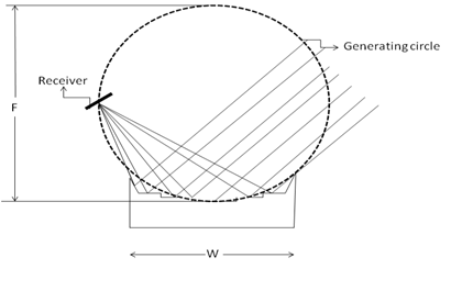
Figure 16 Sketch of the FMSC with focal length and reflector width ratio F/W= 1.5.

Figure 17 Sketch of the CSFMSC with focal length and reflector width ratio F/W= 1.
Linear fresnel reflector
Linear Fresnel reflector is a compact linear Fresnel reflector (CLFR). It is also referred to as a concentrating linear Fresnel reflector. Linear Fresnel reflectors use long, thin segments of mirrors to focus beam radiation onto a fixed inverted flat absorber situated at a common focal point of all reflectors. These reflectors are capable of concentrating the sun’s beam radiation to approximately thirty (30) times its normal intensity which gives concentration ratio of 30 as shown in Figure 18. This concentrated solar energy is transferred after absorption to working fluid generally typically oil having boiling temperature very high. The heated fluid (~300℃) goes to power a steam generator through a heat exchanger. Abbas et al.,82 presented the steady state thermal behavior of a flat receiver of linear Fresnel concentrator. They have reported that the maximum exergy of LFR at the fluid outlet temperature of 300 °C for a 300 m receiver with 8.33 kW/m2 impinging radiation at inlet temperature of 200°C was about 30.5%. The maximum thermal efficiency has been reported as 56%. The rate of thermal energy gain (increase in specific enthalpy) of the working fluid flowing with mass
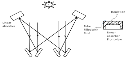
Figure 18 Sketch of a linear Fresnel concentrator.
flow rate
is as follows:
……………….. (23)
The
and
are outlet and inlet temperature of working fluid in receiver. The rate of thermal energy gain through intermediate heat exchanger on basis of heat transfer equation is given by
……………….. (24)
Where εf is the geometry factor of an intermediate heat exchanger which can be considered as one due to the similarity between the receiver behavior and an intermediate heat exchanger, A is the heat exchange surface area and ΔTlm is the log mean temperature difference along the receiver. The ‘h’ is the heat transfer coefficient from the inner surface of the tubes to the working fluid which is can be evaluated, Gnielinski83 by the correlation as follows:
……………….. (25)
Where Re and Pr are the Reynolds and Prandtl numbers and f is the friction coefficient in tube. The value of h is about 1500 W/m2°C at 350°C. The value of f varies between 0.0275-0.03 for operating temperature between 200 to 400 °C. It decreases with increase of temperature.
The exergy and thermal efficiency of linear Fresnel reflector (LFR) in a steady state are given by
……………….. (26)
And
……………….. (27)
The pumping power, , to overcome the pressure drop associated to the fluid motion in above equation is given by
……………….. (28)
The numerical values of
increases from 0 to 2.25 kW with increase of number tubes in receiver from 10 to 50. An expression for the mass flow (
) and the pressure drop (
) for the hydraulic process characterization are given by
---------------------- (29)
And
----------------------- (30)
Where the factor ‘2’ is given by the fact that the flowing fluid must come back after passing through the receiver.
The convective and radiative heat losses from the inverted trapezoidal cavity receiver for solar linear Fresnel reflector (LFR) has been estimated by using a two dimensional (2-D) numerical model, Reddy et al.,84 They found that the total heat loss from the inverted trapezoidal cavity receiver varies from 663.47 W/m to 1046.3 W/m for medium temperature (400 °C). It was reported by Sahoo et al.,85 that radiative component of losses from a trapezoidal cavity was dominant which contributed around 80-90%. This agrees with the result reported by Abbas et al.,82; Lin et al.,86 conducted an experiment and showed that an overall heat loss coefficient of V-shaped cavity receiver in a linear Fresnel reflector (LFR) solar collector varied from 6.25 to 7.52 W/m2 K for temperature range of 90 to 150°C as per expectation. It was also noted that as the average surface temperature increased from 90 to 150°C, the thermal efficiency decreased from 45% to 37%. A new design of semi-parabolic linear Fresnel reflector (SPLFR) solar concentrator has been proposed by Zhu et al.,87 The SPLFR is fabricated by linear plate mirrors whose edges located at a parabolic shape line. Based on the ray trace simulation results, it has been observed that the SPLFR has the same concentrating efficiency as that of the parabolic trough concentrator (PTC) with lower manufacturing cost. It is consisted with many linear plate mirrors like linear Fresnel reflector (LFR). To minimize cost per exergy, Nixon et al.,88 studied a new method for the optimization of the mirror element spacing arrangement and operating temperature of linear Fresnel reflectors (LFR). Their main objectives were to maximize available power output (i.e. exergy) and operational hours. The results showed that the exergy averaged over the year was increased from 9% to 50 W/m2 with an additional 122 h of operation with cost per exergy of 2.
Central heliostat tower receiver
A heliostat is derived from Helios (the Greek word for sun) and stat (stationary). It is a device which includes a plane mirror which turns to keep reflecting sunlight toward a fixed target shown in Figure 19. This arrangement compensates for the sun's apparent motions in the sky. The fixed target acts as a receiver which is at distant from the heliostat. The reflective surface of the mirror is kept perpendicular to the bisector of the angle between the directions of the sun and the fixed target as seen from the mirror. The fixed target is stationary relative to the heliostat to reflect beam radiation in a fixed direction. The heliostats are normally used for
- Day lighting and
- To generate electricity. They can also be sometimes used in solar cooking. Hammache et al.,89 investigated the thermal efficiency and cost evaluation of high temperature solar heat to produce hydrogen with different levels of yearly direct insolation for various locations at normal incidence from central receiver systems. The study has been carried out with an external vertical cylindrical receiver and for slant sizes ranging from 100 MW to 900 MW. It has been reported that an overall thermal efficiency of the system varies from 51.3 % to 56.1%. The levelized thermal energy cost was in the range of 10 $ GJ for favorable locations. Galal et al.,90 showed that when the operating temperature was increased from 500 to 1300°C the thermal efficiency of heliostat system decreased from 75% to 55% with down looking cavity type receiver. Further, Collado et al.,91 made a calculation of the annual thermal energy supplied by a defined heliostat field. A method for the designing of the heliostat field layout has been developed for solar power plant for many researchers [89-95]. Segal et al.,96 optimized the working temperatures (above 1000K) of solar central receiver to increase its overall efficiency. It was found that when operating temperatures were 1600K and average field density was 35% the maximum overall efficiency was obtained. Recently, a genetic algorithm was developed by Besarati et al.,97 to obtain the optimal flux distribution on the receiver surface of a solar power tower plant. Some of the recent working solar thermal power plants based on central heliostat tower receiver technology have been given in Table 1;94,14-18
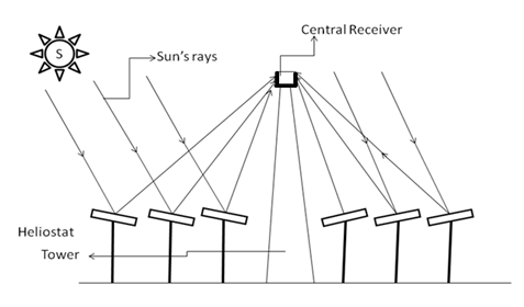
Figure 19 Sketch of a central heliostat tower receiver.
Hemispherical bowl mirror, Tiwari61
It consists of a hemispherical mirror as shown in Figure 20.98 which is always fixed. A tracking linear absorber is also present in it. Here, two-axis tracking is necessary. The absorber is moved so that its axis is always aligned with rays passing through the centre of hemisphere. The linear absorber is pivoted at the centre of curvature of the mirror. The solar rays after reflection enter the hemisphere and cross the paraxial line at some point between the focus and the mirror surface. These designs of concentrator have a lesser concentration because of spherical aberration than the paraboloidal concentrator.
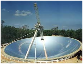
Figure 20 A hemispherical bowl mirror.98


