New composite materials have been developed over the past decade to address the common issue of plate buckling, which is undesirable in most cases. However, to avoid plate buckling, the calculations used to forecast plate design must be accurate. A complete understanding of the mechanical behavior of plate materials is possible when calculations are based on the boundary conditions and the type of functionally graded material (FGM) of which a plate is constructed.
FGMs are composite materials, typically consisting of metal and ceramic, with varying properties and thicknesses. A group of Japanese researchers first registered FGMs in 1984.1 FGMs, advanced high-performance, heat-resistant materials, withstand extremely high temperatures and large temperature gradients. Typically, FGMs. Tailoring material properties for a specific application is an advantage. For plate stability, the critical buckling load is the most important factor in design, and the computed buckling coefficient depends upon the criteria used to define the failure point of the plate.
In the last few decades, the buckling of rectangular FGM plates has been studied. By employing higher-order shear deformation, Reddys2 presented a finite element formulation theory for the linear and nonlinear thermo-mechanical response of FGM plates. Vel & Batra3 investigated the exact solution for the thermo-elastic deformation in FGM, simply supported, thick, rectangular plates. Javaheri & Eslami4 also studied the buckling of fully simply supported FGM plates, when subjected to thermal loads and uniform in-plane compression using a variational approach based on classical plate theory. They employed equilibrium and stability relationships to investigate the buckling behavior of fully simply supported FGM plates using the thermal buckling of FGM plates reported in other research work, which relied upon higher-order shear deformation plate theory. In addition, Samsam et al.5 presented buckling analysis of fully simply supported, thick, rectangular, functionally graded plates subjected to thermal and mechanical loads. The equilibrium and stability equations were derived using third-order shear deformation plate theory. The effect of imperfection on the buckling load of fully simply supported FGM plates subjected to in-plane compressive and thermal loading was taken into consideration in other studies using classical plate theory.6
Zhao et al.7 analyzed the mechanical and thermal buckling of functionally-graded ceramic-metal plates, consisting of arbitrary geometry, by using first-order shear deformation plate theory in conjunction with the mesh-free, kp-Ritz approach. The displacement field was estimated in terms of a set of mesh-free kernel particle functions; the bending stiffness was measured using a stabilized conforming nodal integration, and the shear and membrane terms were computed using a direct nodal integration method to eliminate the shear-locking effects of very thin plates. Bodaghi & Saidi8 presented an analytical approach to the buckling analysis of thick, rectangular FGM plates, using various boundary conditions in which the coupled governing stability equations of FGM plates were converted into two uncoupled partial differential equations in terms of transverse displacement and boundary layer function. The Levy-type solution was employed to solve these equations for rectangular, functionally graded plates with two simply supported opposing edges. Hoang & Nguyen9 presented a simple analytical approach to the stability of functionally graded plates under in-plane compressive, thermal, and combined loads. Equilibrium and compatibility equations for functionally graded plates were derived using classical plate theory, taking into account both geometrical nonlinearity, in the von Karman sense, and initial geometrical imperfection, while the resulting equations were solved by the Galerkin procedure to obtain explicit expressions of post-buckling load-deflection curves.
In comparison to exact method and numerical methods, such as the finite element method, the finite state machine (FSM) first introduced by Cheung10 provides more efficient formulations for the investigation of plate buckling behavior under different load conditions. Ghannadpour11 and his colleagues used the FSM to investigate the buckling of rectangular, functionally graded plates under three types of mechanical loading: uniaxial compression, biaxial compression, and biaxial compression and tension. These authors also investigated thermal buckling of functionally graded plates using FSM. Sarami et al.12 studied buckling of functionally graded, stiffened and unstiffened plates using the finite element method. Mozaffari & Ayob13 investigated the effect of thickness variation on the mechanical buckling load in plates made of FGMs. Tai et al.14 studied thin and medium-thick FGM plates’ micro versions, using a modified couple stress theory. To date, only a few studies have directly evaluated the displacement behavior of rectangular FGM plates. Therefore, this study employed the Galerkin method to investigate the static behavior of FGM plates used in ceiling and floor cubic tanks subjected to uniform uniaxial compressive loading under different boundary conditions.
Given the importance of subject, a number of recent studies investigated characteristics and behavior of FGM tanks Figure 1. For example, Bakhsheshi & Khorshidi15 investigated the free vibration of FGM rectangular plates in contact with turbulent fluid. They applied a trigonometric theory; with a third harmonic function for the wall of cubic tanks under different boundary conditions. Moreover, Tahani & Talebrian16 performed an analysis of cylindrical FGMs under symmetrical mechanical loads with two-cantilever support using a finite element method. In a study conducted by Tohidi, Abariniaand & Naei,17 thick FGM plates used in spherical tanks were subjected to heat and pressure loads, and the environmental stresses were calculated. Lastly, a general model was developed to calculate the radial and circumferential stresses within thick-walled FGM spherical tanks.
Additionally, Safari, Tahani & Hosaini18 assessed the analytical method for dynamic response of thick-walled cylinders under mechanical shock. Thus, the equation employing a Laplace domain, using a series of cylindrical targeted and dynamic responses in the time domain residuals, was obtained using a theoretical analysis. Eicivand, Setareh & Jahani19 studied the effect of both boundary conditions-clamped-clamped and clamped-free-on the vibration of FGM cylindrical plates made of stainless steel with a nickel ring and stiffeners. That study followed a third-order shear deformation theory, and a frequency effect of the ring with stiffener leaves was also found in that study. Cylindrical shells were targeted by varying the volume fraction of behavior and characteristic frequencies. Furthermore, a study by Abdolvahab20 examined the application of FGM plates made of metal ceramic used for structural design in cubic and cylindrical tanks for storage of sludge in wastewater treatment plants. Considering these prior studies, there has been no previous static analysis of FGM ceiling and floor plates within cube tanks subjected to uniform compression perpendicular to the mid-plane. This research fills that gap .21-25
Geometry of the problem
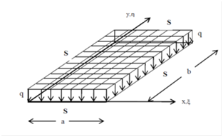
This study investigated the rectangular floor and ceiling FGM plates used in cubic tanks, and the geometry of these FGM floor plates consisted of rectangular, thin plates. The surface of the ceramic side was in contact with fluid Figure 2,26-28 metal and subjected to uniform compression perpendicular to the mid-plane with all edges fully simply supported. The geometry of the FGM ceiling plate consisted of a rectangular, thin plate. The surface of the metal side was in contact with fluid, or air Figure 2, ceramic and subjected to uniform compression perpendicular to the mid-plane, similar to a snow load.

Figure 2 The right schematic cross-section of floor FGM plate with thickness h in cube tank, schematic diagram on the left is the ceiling of FGM plate under uniform load.
The use of a polynomial with trigonometric functions facilitated an easy calculation for changing boundary conditions. In this method, a sine function was applied for
direction, while a polynomial function was used for
direction. Because it is difficult to extract a trigonometric function alone to represent a deflected shape, a combined trigonometric and polynomial function was employed.29
FGMs are a mixture of ceramic and metal or a combination of different metals made by gradually varying the volume fraction of the constituent materials. The FGM can be continually produced by varying the constituent multi-phase materials in a predetermined profile. The most distinct features of an FGM are its non-uniform microstructures within its continuously graded properties. FGMs can be described by variations in volume fractions, exponential function, or sigmoid function. Most researchers use the power-law function in which the material properties gradually varied from a bottom surface of pure metal to a top surface of pure ceramic, as shown in the section of the plate in Figure 2. To acquire the effective thermal and mechanical properties of an FGM plate, a simple mixture rule based on a power-law distribution for which the material properties vary throughout the thickness of the plate was assumed as
(1-a)
where subscripts m and c referred to the metal and ceramic constituents, respectively. P denoted a property of the material, and z was measured over the thickness of the plate. In Eq. (1-a), V was the volume fraction of the ceramic phase, and it was represented by a power-law distribution such that
(1-b)
In which h was the thickness of the plate, n was the power-law index, which is always positive, and z was measured from the geometric center of the plate, in which -(h/2) < z < +(h/2). Figure 3 shows the variation of the ceramic volume fraction throughout the thickness of the plate for different volume fraction potencies. The plate is fully ceramic when n = 0, while the composition of ceramic and metal takes a linear shape when n = 1.
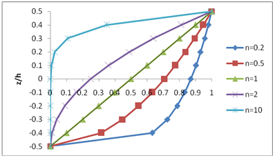
Figure 3 Variation of volume fraction over the thickness for different values of power index n.
Mathematical formulation the floor and ceiling FGM Plates
The final differential equation for the FGM plate, considering the loads on the plate, (q), was obtained as follows:
(2)
where D ̅ was the flexural rigidity of the FGM plate, and w was the displacement of the plate along the z-axis.

Figure 3 Variation of volume fraction over the thickness for different values of power index n.
Displacement depends on bending rigidity and the amount of uniform loading parameters perpendicular to the plate. Assuming a constant uniform load value on the floor and ceiling tank plates, the bending rigidity parameter of plates was representative of the floor and ceiling under static analysis. This section presents the flexural rigidity of the FGM floor and ceiling plates within a cubic tank.
(3)
The flexural rigidity of FGM floor plates, where the top surface of the plate faced the load and was made of ceramic, was calculated using Eq. (4) through (6):
(4)
(5)
(6)
However, the flexural rigidity of FGM ceiling plates, where the top surface of the plate faced the load and was made of metal, can be calculated using Eq. (7) through (9):
(7)
(8)
(9)
where Ec and Em represented the modulus of elasticity of ceramic and metal, respectively.
As illustrated in Figure 4, the bending rigidity of FGM plates appeared as follows: the metal part of the plate was Aluminum
and the ceramic part of the plate was Alumina
. The Poisson's ratio of the plate was equal to 0.3
. The thickness of the plate was 0.01 of the length of the plate. The n value varied between zero and one hundred. Figure 4 shows that by increasing the value of parameter n, the flexural rigidity of the FGM plate on the floor of the cubic tank was more than that of the ceiling plate.
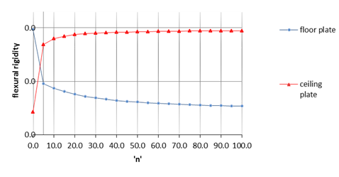
Figure 4 Variation of flexural rigidity of the FGM plate used in ceiling and floor of tanks for different values of ‘n’.
Interpretation from
Figure 4 shows that until n = 1, the flexural rigidity of the FGM plate in the ceiling plate of the cubic tank was lower than that of the floor plate. However, if n was more than 1, the flexural rigidity of the ceiling FGM plate was more than the bending rigidity of the floor plate.
Galerkin method for loading perpendicular to the mid - Plane
In this study, evaluation was based on an FGM rectangular plate, in the thickness as shown in , which was under constant uniform load on the surface of the plate perpendicular to the mid-plane with variation in the flexural rigidity parameter, and with fully simply supported boundary conditions for both the longitudinal and transverse edges.
Plates’ behavior analysis can be applied to trigonometric functions in the longitudinal direction of the plate that satisfies boundary conditions. To satisfy the boundary conditions in the transverse direction of the plate, a polynomial function was employed due to the difficulty in meeting the requirements of trigonometric functions. Simply supported (denoted as S) and clamped supported (denoted as C) plates are illustrated in the following figures.
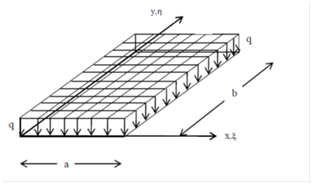
Figure 5 Model rectangular plate under uniformly load perpendicular to the mid-Plane.
To solve the problem and maintain clarity of presentation, Eq. (2) was non-dimensionalized by substituting
(10)
where a and b were the length and width of the plate, respectively; W was the non-dimensional form of the displacement of the middle surface of the plate in a direction normal to the undeformed middle surface.
Thus, Eq. (2) was re-written as follows:
(11)
The solution of Eq. (11) is taken in the form
(12)
Eq. (12) was simplified to yield a fourth-order partial differential equation with variable coefficients for which a closed form solution would be difficult, if not impossible, to obtain. Therefore, Galerkin’s series method was employed to solve the problem.
The function precisely described the deflection of the transverse direction of the plate.
(13)
The function was taken as polynomial with four constants (four boundary conditions), as shown in Eq. (14).
(14)
These constants were evaluated through applying the equations in Table 1.
Longitudinal edges is
Simply supported(S)
|
|
|
Longitudinal edges is
Clamped(C)
|
|
|
Table 1 Boundary condition for calculation
To get the deflection function corresponding to the number of series, the constants were substituted into Eq. (12)
(15)
For simplicity
(16)
Where
(17)
The number of half waves, m in Eq. (13), depended on the aspect ratio of the plate. Indeed, m indicated the mode shape in which the plate buckles. Substituting Eq. (16) into Eq. (11) leads to an expression simplified to a fourth order differential equation. The final form of the governing differential equation is
(18)
(19)
By applying the Galerkin method and using weight functions, differential Eq. (19) can be solved
(20)
Equation (20) leads to a square matrix as follows:
(21)
In which
(22)
In this relationship, matrix [L] represented the stiffness matrix for the plates. The second part of Eq. (20) or the force was
(23)
Also:
(24)
Displacement of the plate was calculated with Eq. (25)
(25)
Finally, displacement of the plate was obtained using Eq. (26)
(26)
Based on the results obtained from the previous sections, a computer program was developed using Matlab software. After calculating the stiffness matrix, it was possible to assess the maximum displacement using Eq. (26). The example static analysis for FGM ceiling or floor rectangular plates of various thickness are illustrated in Figure 2, using the assumptions of Section 6. Moreover, Figures 7 through 9 demonstrate the maximum displacement
of an FGM plate, proposed with various aspect ratios for different n values, fully simply supported (SSSS), and subjected to a uniform load equal
.
Floors and ceilings plates of cubic FGM tanks under perpendicular mid-plane loading
The maximum amount of displacement
, in mm, is shown in Figures 7 & 8, for FGM floor or ceiling plates of cubic tanks with loading perpendicular to the mid-plane, and with fully simply support edges. Charts were based on aspect ratios between 0.5 and 5, and for 0, 0.5, 1, 5, 20,
. Figures 7 & 8 reveal that with an increase in maximum displacement
of rectangular FGM floor and ceiling plates, the aspect ratio of plates increased. Additionally, by increasing the value of the parameter n for floor rectangular plates with constant boundary conditions, under loading perpendicular to the mid-plane, the maximum amount of displacement
also increased. However, with an increase in the value of the parameter n for tank ceiling rectangular plates with constant boundary conditions, under loading perpendicular to the mid-plane, the maximum amount of displacement
decreased.
The combination of Figures 7-9 represents the maximum displacement of fully simply supported (SSSS) FGM plates on the floor or ceiling of tanks subjected to uniform compression perpendicular to the mid-plane Figure 9. Comparison Chart of maximum displacement (mm) rectangular floor or ceiling of FGM plate, under load uniformly perpendicular to mid-plane with fully simply supported (SSSS)

Figure 7 The maximum displacement (mm) rectangular floor plate of FGM, under load uniformly perpendicular to mid-plane with fully simply supported.
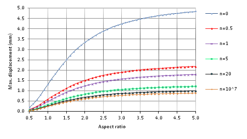
Figure 8 The maximum displacement (mm) rectangular ceiling plate of FGM, under load uniformly perpendicular to mid-plane with fully simply supported.
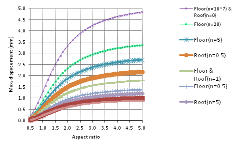
Figure 9 Comparison Chart of maximum displacement (mm) rectangular floor or ceiling of FGM plate, under load uniformly perpendicular to mid-plane with fully simply supported (SSSS).
The same boundary conditions used in the FBM floor or ceiling plates subjected to uniform loading, for n=1 (when the rigidity of the floor and ceiling plate was constant) are shown in Figure 9. The maximum displacement of the plate was constant. Using a homogeneous ceramic plate for the floor and ceiling of tanks (Floor (n=0) & Roof (n= 10^7)) with the same boundary conditions, the maximum displacement was the lowest. However, using a homogeneous metal plate for the floor and ceiling plates (Floor (n=10^7) & Roof (n= 0)), the maximum displacement would be the highest.


