MOJ
eISSN: 2572-8520


Research Article Volume 1 Issue 3
Research Associate in Anthropology, University of Chicago, USA
Correspondence: Charles R Ortloff, Research Associate in Anthropology, University of Chicago, 18310 South view Avenue, Los Gatos, CA 95033, USA
Received: October 20, 2016 | Published: November 25, 2016
Citation: rtloff CR. New discoveries and perspectives on water management at 300bc-ad 1100 tiwanaku’s urban center (bolivia). MOJ Civil Eng. 2016;1(3):57-66. DOI: 10.15406/mojce.2016.01.00014
The 300 BCE- CE 1100 pre-Columbian site of Tiwanaku located on the high altiplano of Bolivia demonstrated an advanced use of hydrologic and hydraulic science for urban and agricultural applications that is unique in the Andean world. From recently discovered aerial photos taken of the site in the 1930’s, new perspectives of the water system of the ancient city, beyond previous interpretations of a major drainage canal as a dividing ‘moat’ between ceremonial and secular parts of the city, are now possible from new discoveries of a network of water channels not previously known. Surrounding the ceremonial core structures of urban Tiwanaku was a large encompassing drainage canal that served as the linchpin of an intricate network of spring-fed supply and drainage channels to control both surface and groundwater aquifer flows. The drainage canal served to:
The hydrological regime of Tiwan
Of interest to present-day engineers are the engineering accomplishments of ancient civilizations. In the discussion to follow, the pre-Columbian 300 BC- AD 1100 city of Tiwanaku located in the high altiplano (~4500 masl) region of Bolivia demonstrates use of advanced hydrologic principles to maintain city drainage during the long rainy season through a complex network of surface and subsurface channels. This water control system involves both groundwater stability control coupled to spring-supplied surface channels to perform health and monument maintenance benefits to city inhabitants and, as such, is a unique demonstration of hydrologic engineering not seen at any other pre-Columbian South American site. Research at the site of Tiwanaku has revealed that the city’s ceremonial center, composed of monumental architecture and elite residential compounds, is circumscribed by a large drainage channel (Figures 1-5 W-D-V-X). While previous researchers correctly interpreted its main purpose as a boundary separating sacred and secular urban areas of the city, the encircling channel additionally served as a hydraulic regulator enhancing aquifer drainage to promote rapid post-rainy season soil dry-out as the dry season progressed. Water collecting in the drainage channel from aquifer drainage, rainy season runoff and flow from canals intersecting the drainage channel rapidly exited through connecting canals to the Tiwanaku River to limit groundwater recharge during the rainy season; during the dry season, continued aquifer seepage and flow from adjacent canals recharged the groundwater to maintain and stabilize its height through seasonal changes. One net effect was to stabilize the groundwater layer through rainy and dry seasons to maintain the bearing strength of soil under large monuments within the ceremonial center to limit structural distortions.1 Water accumulating in the drainage channel from aquifer drainage and channeled spring water flow provided flow through dual subterranean channels to flush human waste delivered into the subterranean channels from elite structures to maintain hygienic conditions in the residential compounds. The multi-faceted hydrological aspects of the drainage channel thus served city environmental and hygienic conditions through rapid soil drying in city living areas while promoting structural stability for its many monuments as well as aiding in rainy season drainage from the Sunken Temple (Figure 5,F) floor. While groundwater control mastery is apparent in the urban setting, additional research on Tiwanaku raised field agriculture indicates similar advances in use of groundwater control technology not previously reported in the literature. To demonstrate the seasonal interaction of surface and aquifer water flows, a porous media aquifer model is utilized for computational fluid dynamics analysis to demonstrate the inland drainage channel’s role as a hydrological control element vital to the city’s sustainability during wet and dry seasons.
Settlement history
The ancient (300 BC- AD 1100) city of Tiwanaku, capital of a vast South American empire, has been the subject of research starting from early 20th century scholars that continues to the present day.2-17,27-39 The city, located at the southern edge of the Lake Titicaca Basin in the south-central portion of the South American Andes at an altitude of 3800-3900 m.a.s.l. incorporated an elite area bounded by an encompassing drainage channel that supported temple complexes, palace architecture and a seven-stepped monumental pyramid (Akapana) designed to serve ceremonial functions and provide residential structures for Tiwanaku’s rulers. Outside of this center lay a vast domain of urban housing structures. An intricate network of canals acting in conjunction with the drainage channel performed several hydrological functions: rapid ground drainage during both wet and dry seasons to promote health advantages for the city’s ~20,000 inhabitants; flood defense to preserve the ritual center and surrounding urban structures and, most importantly, height excursion control and stabilization of the deep groundwater base underlying the site. This latter hydrologic function prevented dry-out collapse of the deep aquifer that preserved soil bearing strength that limiting subsidence of foundation soils underlying monumental structures within the drainage channel’s boundary. The management of water systems within the city demonstrates hydrologic engineering expertise consistent with that found in Tiwanaku’s raised-field agriculture4,6 and demonstrates Tiwanaku hydrologic engineering mastery.
Newly discovered aerial photographs taken in the 1930s provide data to interpret the extent of, and insight into, the hydrologic function of the drainage channel. The early photographs reveal traces of the drainage channel’s north and south arms in addition to a (newly discovered) north-south canal [Mollo Kontu canal M (A-B), (Figures 1-3 & 5)] intersecting the southern drainage channel arm. The drainage channel collected flow from adjacent canals, rainfall runoff and infiltrated rainfall seepage from the saturated, near-surface phreatic of the aquifer as well as from the deep groundwater aquifer (as the drainage channel depth intersected to top portion of the deep groundwater layer) to then transfer water into the nearby Tiwanaku River during the rainy season to prevent deep groundwater recharge. During the dry season, phreatic aquifer seepage into the drainage channel plus water from the intersecting Mollo Kontu canal maintained the deep groundwater aquifer level relatively constant while surface evaporation and recession of the near-surface phreatic aquifer served to rapidly dry the ground surface promoting health and livability benefits for city inhabitants. The design intent of the builders of the drainage channel envisioned control of the deep groundwater level through wet and dry seasons to maintain the physical integrity of monumental structures by preventing the dry-out collapse of the deep aquifer underlying the main ceremonial core. Given a stable upper boundary of the deep groundwater layer throughout the year, physical strength properties of foundation soils were maintained thus limiting structural distortion and settling of the massive platforms of the Kalasasaya temple and Akapana pyramid (Figure 5,R) within the ceremonial center. Additionally, with the stable groundwater layer well below the floor of the Sunken Temple (Figure 5,F), rainy season aquifer drainage was facilitated into the drainage channel. Thus, beyond the drainage channel’s role in creating a ritual and social boundary between the ceremonial center and secular residential city districts, its engineering design contributed many practical benefits to living conditions for city residents throughout wet and dry seasons.
Tiwanaku hydraulic analysis
To demonstrate the drainage channel’s hydrologic functions, multiple data assemblages used to construct a Computational Fluid Dynamics (CFD) hydrological model (Figure 5) include results of archaeological mapping and excavation,18-25 Google Earth imagery and the 1930s aerial photos taken over the site of Tiwanaku. These aerial photos reveal the site decades before modern urbanization and monument reconstruction began and were taken at a time of year when many features held water thus providing a clear view of Tiwanaku’s hydrological features. From these photographs, the outline of the drainage channel is shown in Figure 1 as the dark encircling boundary to the ceremonial center. The curvature of the drainage canal V-D-W-X shown in Figure 5 is derived from earlier observations of the canal.8,10,11 made before years of erosion and soil deposition infilling to the present day.
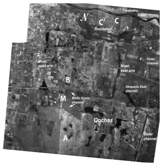
Figure 1 Aerial photo view of the inland drainage channel surrounding the ceremonial core of Tiwanaku indicating the intersecting Mollo Kontu (M) canal, qocha.
The east drainage canal arm denoted Moat: east arm, Figure 1 averages 5-6 m deep and ranges 18-28 m in top width. Subterranean canals originating from the drainage channel’s south arm were drainage conduits for Tiwanaku’s monumental and elite residential structures.9 Since the south arm of the drainage channel is shallower in depth than the north arm as determined by ground contour measurements,11 a fraction of the water that accumulated in this arm flowed down-slope through the drainage channel’s east and westarms toward the Tiwanaku River while a portion of accumulated water in the south arm flowed into the dual subterranean channels (Figure 4 & 5) underlying the ceremonial center region. Given the two degree declination slope of the subterranean channels toward the north, water accumulating in the drainage channel’s bottom during the wet season and dry seasons provided cleaning flushing water for the Putuni palace’s waste removal/drainage facilities. The north canal section (Figure 1 & 5) is vital for understanding an additional feature of the drainage channel’s hydrological function. North of Tiwanaku’s northwest monumental complex, the shallow alluvial plain drops sharply down toward the Tiwanaku River’s marshy floodplain. One portion of the east arm of the canal turns west and disappears into the floodplain (Figure 1-C’) while canal (C) continues north toward the Tiwanaku River. One portion of the west drainage channel arm leads into the marsh north of the Kalasasaya (Figure 2 & 5) while an ancillary arm continues northeast toward the river. The north portion of the drainage channel thus divided into several branch canals that intersected the floodplain and drained accumulated water from the north arm of the drainage channel. Water not directly shunted to the Tiwanaku River through canal C (Figure 1,5) drained water in the floodplain’s aquifer that drained into the Tiwanaku River. The floodplain area thus served as a productive agricultural system for the urban center by utilizing its available water surplus.
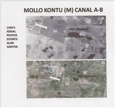
Figure 2 Details of the intersection of the Mollo Kontu canal with the southern arm of the drainage channel. Source: Alan Sawyer aerial photographs.
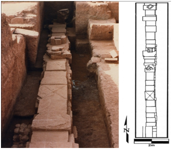
Figure 3 The Mollo Kontu canal (M) and surface features from Google Earth satellite imagery used to compose Figure 5.
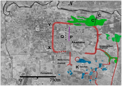
Figure 4 Photo and plan view of the excavated portion of the subterranean Putuni channel P. Image from Couture and Sampeck, 2003: 235.
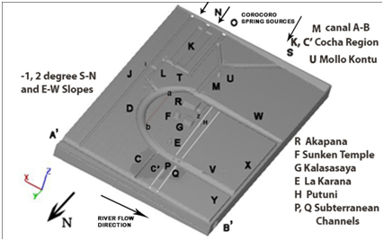
Figure 5 Representative CFD model of hydrological and architectural features of the Tiwanaku urban center. Model is a best-estimate representation of the 9-10th century AD site geometry scaled from aerial photos, historical sources and ground survey; line a-b represents a later drainage path interpretation compared to earlier curved versions by Posnansky 1945 & Bandelier 1911 used for the model.
The drainage channel in the urban hydrological network
Where the groundwater surface emerged from depressed areas, springs formed. Several canals in the southern portion of Tiwanaku were engineered to utilize this canal water input. The westernmost Choquepacha area’s canal26-28 derived from a natural spring on a bluff southwest of Pumapunku. The spring was fitted with a basin that included several incised canal stones carved to convey water,9 II: (Figure 4 & 2). Combined with the output of an adjacent stream that drained a marshy area of the terreplein, the Choquepacha area supported extensive terrain amenable to pastoral grazing and farming immediately to the west of the Tiwanaku urban area.19 Other features relate directly to the hydrological function of the drainage channel. The first feature is a north-south Mollo Kontu canal that supplied water from springs originating from the southwest portion of the site near the Pumapunku complex into the southwest portion of the drainage channel (Figures 1-M, 2-M, 3-M and 5 S-M). The second feature is an interlinked cluster of sunken basins, or qochas, that occupy the southeast or Mollo Kontu portion of the site (Figure 1, 5K). Qochas are pits excavated into the phreatic aquifer layer that capture and store rainwater and serve to expand planting surfaces and pasturage while creating micro-lacustrine environments that attract waterfowl.27-30 Figure 1 depicts a series of canals dendritically linking the qochas to one another with a branch connecting to the Akapana East canal L, (Figure 5) that drained into the east arm of the drainage channel. The third major feature is a long, narrow, outer canal (J) on the east side of Tiwanaku (Figure 1,2,5). While the overall role of this canal is unclear, its southern portion is straight and follows an alignment that mirrors that of the Pumapunku complex to the west; its northern portion shifts course and bounds the east edge of the site. The east canal (Figure 5,L) links with the drainage channel (Figure 1 & 5, W-D-V-X) by connector canal I indicating that the outer canal was part of an encompassing urban hydraulic network. The areas immediately east of the canal contain Tiwanaku’s residential sectors and include Ch’iji Jawira, a barrio of ceramic producers that depended on a constant water supply.31-35 Immediately east of the Ch’iji Jawira sector is a low brackish marsh; from this marsh, the outer canal (J) likely provided fresh water from springs for Tiwanaku’s easternmost residential sectors and drainage of excessive canal flow during the rainy season.
The east and west arms of the drainage channel directed water around the monumental complex toward the Tiwanaku River to the north (Figures 1, 5 A’-B’). The C’ floodplain was an integral part of Tiwanaku’s larger hydraulic network that served to facilitate drainage of both groundwater seeping from drainage channel arm D-V (Figure 5) and rainwater runoff during rainy season peaks. Intricate surface canals and dual subterranean stone-slab constructed canals (Figure 4 & 5) provided additional drainage within the area bounded by the drainage channel. The elaboration of surface canals on the interior floor of the Sunken Temple (Figure 5,F) and areas outside the Kalasasaya (G)36,37 indicate a drainage connection to either (or both) the drainage channel and the subterranean channel P (Figure 5); additional drainage by seepage into the stabilized low groundwater layer also helped to keep the temple floor dry throughout seasonal changes. The Akapana pyramid (Figure 5,R) incorporated an intricate, stone-lined canal network that routed water from the uppermost down through successively lower platforms and finally out through several portals in its basal terrace31,32 to several open surface basins draining into vertical pipes (and/or the drainage channel) that conveyed water into the subterranean canals P and Q (Figure 4 & 5) into drainage channel arm V (Bennett 1934:378-385). Canal P provided flushing water to remove human waste from the Putini residential compound for conveyance to the Tiwanaku River. Water was temporarily pooled in the sunken courtyards near platform monuments strategically rendering them lakes for ritual events and reservoirs for controlled water distribution.
Excavations between Putuni and Kerikala complexes indicated structures within the ceremonial core region that articulated with Tiwanaku’s subterranean drainage network. This area housed high status groups until, at approximately AD 800, the construction of the Putuni platform repurposed the space to support recurring state-sponsored ceremonies.11,38,39 Located 2.5m below the current ground surface, canal P (Figure 4 & 5) consisted of sandstone slab masonry with vertical standing slabs approximately 1.0 m high and horizontal slabs about 0.8-0.9 m across. Several vertical pipes consisting of multiple stacked, perforated stone disks conducted surface water from features within the Putini to the lower subterranean channel P. Water from the drainage channel’s southern arm (V) supplemented by water from canals L and M together with seepage water from both phreatic and top portions of the deep aquifer was used to flush waste water through subterranean channels P, Q located in the west portion of the monumental core.
Models of water management at Tiwanaku
To demonstrate insights related to the hydrological function of the drainage channel, use of Computational Fluid Dynamics (CFD)26 is made for cases that address seasonal variability in water input. Here the equations governing aquifer percolation21 were numerically solved by finite difference methods to show transient water transfer within the aquifer for two seasonal water availability cases. Case 1 considers effects existing at the termination of a rainy season on Tiwanaku’s canal systems and city open surface areas. The rainy season in the south-central Andean altiplano generally runs from November through March. Case 2 considers effects of limited water input from springs and aquifer seepage into the deep groundwater layer during the April through October dry season. Data from aerial photographs, Google Earth imagery, contour maps and ground survey provide the basis for the computational model (Figure 5) to demonstrate hydrological features of the drainage channel and its encompassing hydrological network. A porous soil model (Figure 5) of the subsurface aquifer is used to demonstrate hydrological responses of the canal network and drainage channel for the two cases. Figure 5 model’s surface and subterranean features are on the same scale as Figures 1-3 and represent best-estimate 9-10th century AD water supply and distribution network canal paths inferred from photographic and ground survey data. The canal inlets shown (Figure 5- J,N,&O) are sourced by canalized Corocoro springs located south of the modeled area as are canals (S-M) leading from the Pumapunku area. Key monument architectural and hydrologic features in Figure 5 are:
A-B: the Tiwanaku River, flow direction A to B (east to west)
C: drainage channel to A-B
C’ the drainage and agricultural complex supplied from drainage channel C
E: La Karaña residential complex
F: Sunken (or Semi-subterranean) Temple
G: Kalasasaya
H: Putuni
I: Connecting channel between canals L -K -L and J
K: multiple interconnected qocha region supplied by canal N
L: Akapana East canal, which drained qocha region K toward drainage channel
Arm D
M: Mollo Kontu canal linking supply canals O and S to drainage channel arm W
N: Supply canal to qocha region K
O: Connecting canal to canal M
P and Q: subterranean channel pair with declination slope of two degrees to the river; channel P runs underneath the Putuni H
R: Akapana seven-stepped truncated pyramid
S: branch canal to Mollo Kontu canal M
T: lateral transverse canal to L; shunt canal I to canal J and/or canal drainage to
The drainage channel
U: Mollo Kontu monument
W-D-V-X: the drainage channel circuit around the monumental core of
Tiwanaku; original depth of the canal estimated at 3-5 m at location D.
Y: drainage canal from V to the Tiwanaku River (from 1930s aerial photographic source); its inclusion in the model has a minor drainage effect compared to drainage features C, C’ P, Q originating from the drainage channel Z canal below the west side of the Akapana (R) draining toward drainage canal segment D.
The CFD model19 is composed of a porous medium aquifer duplicating soil material properties (porosity, permeability) found at the site through which groundwater percolates. The CFD model incorporates both the east-to-west ground slope declination and a south-to-north declination observed from field measurements. The momentum resistance to flow in the porous medium representation of an aquifer 2016 is expressed as a vector drag term Fd u where Fd is the porous media drag coefficient and u the velocity vector u = qx i +qy j + qz k with qx, qy, qz velocity components in the i, j, k (x, y, z) coordinate directions respectively (Figure 5). Permeability k is defined as k = Vf μ/ρ Fd where Vf is the volume fraction open volume between soil particles /total volume, μ the water viscosity and ρ the water density. For the present analysis, k is on the order of ~10-11 cm2 based upon the site soil type within the model area excepting monumental paved areas for which k is on the order of ~10-15 cm2. For model area soils, 0.43 < Vf < 0.54. Based on these estimates, the average drag coefficient Fd is estimated to be ~0.80. While deviations from this value occur due to varying soil properties with depth and location, flow delivery rates from the saturated part of the aquifer to the drainage channel’s seepage surface (defined as the exposed interior soil surface of the drainage channel exposed to the atmosphere) will be affected but calculations will nevertheless demonstrate qualitative conclusions regarding the drainage channel’s function. In the CFD model, the deep groundwater layer is composed of saturated soil and is stabilized throughout the year at ~5-6 m below the ground surface as well probe data indicates. The saturated phreatic aquifer layer is assumed to lie above the deep aquifer for Case 1 calculations indicative of an intense, long duration rainfall period. The bottom depth of the drainage channel intersects the upper portion of the deep groundwater layer in the Figure 5 model and both the phreatic and deep groundwater layers provide seepage water into the drainage channel together with runoff water and canal water supplied by springs south of the city. For a less intense rainfall period, an intermediate capillary fringe zone extends upward to intersect the bottom reaches of a saturated phreatic layer. Thus deep aquifer recharge can occur when the phreatic layer extends sufficiently downward to penetrate the capillary fringe zone during long duration rainy periods. Again, when rainfall is intense and of long duration, the phreatic and deep groundwater layers merge- for this case, aquifer seepage into the saturated drainage channel bottom cannot occur and excess drainage water is rapidly shunted to the nearby Tiwanaku River. This effect limits the height excursion of the deep aquifer to the base depth of the drainage channel.
For Case 1 analysis, the post-rainy season phreatic is saturated and lies above the saturated deep groundwater layer; as no further infiltrated rainwater can be absorbed into this saturated layer, runoff occurs into the drainage channel. As the dry season progresses, surface evaporation shrinks the phreatic layer upward toward the ground surface and soil drying to depth enhanced by aquifer drainage. In times of extended drought, the phreatic and ultimately the groundwater layer contract leading to soil dry-out conditions to a large depth.
Case 1- Post-rainy season ground saturation conditions
Case 1 examines post-rainfall conditions typical of the end of the altiplano rainy season characterized by phreatic zone saturation and continuous water flow through canals O, S, N, M and J from Corocoro springs (Figure 5). Aquifer seepage to the bottom of the drainage channel from the saturated phreatic layer is transferred to drainage channel arms D, V and W to X-Y and then to the Tiwanaku River (A’-B’, Figure 5) as all these canals have a down-slope toward the river. Additional seepage occurs from the top reaches of the deep groundwater layer into the drainage channel. Water from the drainage channel’s east and west arms then led to the Tiwanaku River through the C canal branch and seepage from the C’ area. Water arriving into inlet N was conducted by canals K and L into either or both canals D and then from I to J. A summary of rainy season water inflows/outflows from a representative section of the drainage channel is shown in Figure 6. Numerical solutions25 of equations governing saturated aquifer and surface/subterranean canal flows give a picture of transient water transfers to/from the drainage channel from seepage and canal flows given estimates of flow rates based on supply spring flow rates. Given Case 1 post-rainy season conditions, surface runoff has been largely collected into the drainage channel and transferred to the river; further water transfer to the bottom of the drainage channel is from aquifer seepage and adjacent canal water flow input- this water is rapidly discharged into the Tiwanaku River as the drainage channel bottom intersects the saturated deep groundwater layer. Figure 7 & 8 show a time progression of water seepage from the drainage channel’s open surface area and progressive surface drying as the phreatic deflects downward due to drainage into the drainage channel.

Figure 6 Summary diagram on water input/output flows on a typical drainage channel section near D (Figure 5).

Figure 7 Post rainy season detail of the east arm of the drainage channel showing the seepage surface conducting water to the bottom of the canal and progressive surface drying for Case 1 conditions.
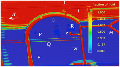
Figure 8 Later time surface drying achieved by aquifer seepage and surface evaporation; note low values of fluid fraction starting eastward on ground surface for Case 1 conditions.
Rapid water removal from the drainage channel via canals C and X-Y to the Tiwanaku River reduced water transfer from the phreatic aquifer to the deep groundwater layer promoting deep groundwater height stabilization. The Akapana monumental core experiences limited rainfall infiltration due to extensive paving and compound roofing that promoted runoff into the drainage channel. Water that managed to infiltrate open areas then drained into the drainage canal and subterranean channel extensions P and Q (Figures 4,5 & 9,10) that directed water toward C’ and to the Tiwanaku River through C’ drainage and C, X-Y canals. As the drainage channel depth extended to the top fringe of the deep groundwater layer, it stabilized the deep groundwater layer depth below the phreatic layer. The location of the Sunken Temple floor (Figure 5,F) above the stabilized deep groundwater layer and its nearness to the drainage channel helped to promote a dry floor through seasonal changes. Here rainfall accumulating on the floor infiltrated into the phreatic layer then drained out to the nearby drainage channel. This effect supplemented channels and piping drainage to the drainage channel. Figure 11 shows fluid fraction results at the inner face of the drainage channel bounding the ceremonial center. The fluid fraction (ff) is defined as the volume of water per unit volume of the porous aquifer; here ff = 1 denotes saturation conditions where water fills the spaces between soil particles and ff = 0 denotes that air fills the spaces between soil particles. Intermediate ff values denote partial water filling of the spaces between soil particles. Results confirm seepage was minimal from what little infiltrated rainwater existed in this largely paved and roofed area as any infiltrated water was conducted into the saturated drainage channel’s bottom and quickly removed by canals C and X-Y to the Tiwanaku River. Figure 9 shows the water transport in subterranean channels P and Q. Channel P lies below the floor of the Putuni; channel Q lies at the same depth as P but ~10 m west of P.9 Vertical pipes connected drainage areas in the Putuni Courtyard and Palace16-18 to canal P with collected water directed toward the V arm of the drainage channel. The P and Q subterranean canals required a regular input of flowing water from canal M and seepage water from phreatic and deep aquifers into drainage channel arm W to maintain residential area hygienic conditions. As the P, Q channels, the C canal, and the drainage channel bottom all sloped downhill toward the Tiwanaku River, water flow from drainage channel arm W directed water and waste solids into the river.
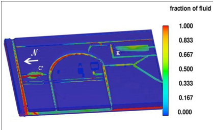
Figure 9 Case 1 fluid fraction results showing water input from canal M to subterranean canals P and Q flushing wastewater from the Putuni complex toward drainage canal arm V and subsequently to the Tiwanaku River A- B.
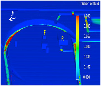
Figure 10 Dry season case 2 fluid fraction results on a cut plane below the ground surface; moisture levels in cocha region K and depressed area C indicate sustainable pasturage and agriculture due to contact with the deep water table.
Case 2- Dry season initiation
Case 2 considers the drainage channel function under dry season conditions zero rainfall and continuous, but limited, water supply from Corocoro springs into surface canals N, O, S and M qocha regions K and C’. Figure 13 indicates that water supply from the M channel plus aquifer seepage continues to supply subterranean P and Q channels to flush human waste from the Putuni elite compound structures. These regions remained functional due to their depth penetration into the receding phreatic zone water level indicating agriculture and pasturage were possible during the dry season. By rapid water transfer of seepage, runoff and adjacent canal water through multiple canal paths in the rainy season to the Tiwanaku River and continued aquifer seepage into the drainage channel together with Corocoro spring-sourced canal water supply in the dry season, the deep water table remained stabilized in height year-round below and distinct from the phreatic zone aquifer. Channels P and Q indicate continued water transport and flushing activity from drainage channel segment W as the dry season progressed with canal M providing water supply during the dry season.

Figure 11 Dry season Case 2 fluid fraction results for the east arm of the drainage canal indicating decreased seepage water into the drainage channel and extensive surface drying.
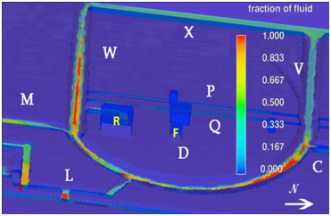
Figure 12 Summary of dry season water inputs/outputs into a section of the inland drainage channel near D (Figure 5).
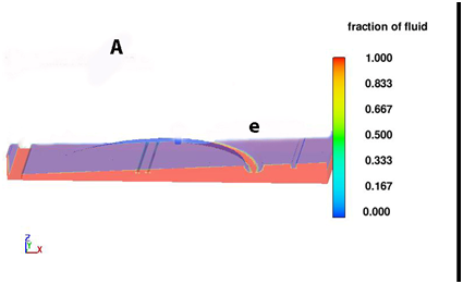
Figure 13 Dry season Case 2 fluid fraction results for the monumental center with decreased water supply from spring-supplied canals; rainfall infiltration and seepage limited by large paved and roofed areas of the ceremonial center.
Additional features of the drainage canal
During the construction of the platform base of the Akapana pyramid, the phreatic aquifer layer was compressed between the heavy base and the deep groundwater layer expelling water into the nearby drainage channel. As additional heavy platforms were added [Seven] and the structure weight increased, further consolidation of the phreatic aquifer below the pyramid base resulted making less water intake available to the phreatic aquifer due to reduction in aquifer porosity. While some rainfall infiltration into the increasingly consolidated foundation base soil occurs, less water amount is available due to lowered foundation soil porosity and rapid drainage into the nearby drainage canal. As platforms were added and the compressive structural weight increased, a consolidated foundation impervious to water infiltration was created ensuring minimal structural deflection and distortion. It is likely that city planning included creation of the drainage channel contemporary with construction of ceremonial core region structures given the planning inherent to the subterranean canals P and Q as well as anticipated hygienic benefits of rapid site drying after the rainy season together with positive consequences of monument stability. The Akapana to this date still retains its structural integrity without settling distortion as a testament to the original planning.
Rainy and dry season groundwater profiles
Figure 14 (A) shows a constant y transect through location D (Figure 5) that indicates a fluid fraction of unity consistent with ground saturation during the rainy season. As the rainy season concluded, drainage into the drainage canal from adjacent saturated soil accelerated surface and ground drying. Figure 6 summarizes all drainage paths relevant to maintain the deep groundwater level during the rainy season. As the dry season progresses, Figure 12 & 13 summarize drainage and water input from canal M that maintains and stabilizes the deep groundwater level. As the drainage canal bottom (e) intersects the top of the deep groundwater layer as indicated in Figure 15B, soil drying to the depth of the deep groundwater layer top is indicated by lower fluid fraction values. This figure indicates that the role of water input from canal M prevents further recession of the deep groundwater layer as the dry season progresses. Thus the intersection of the drainage canal bottom with the deep groundwater layer top provides deep groundwater stabilization that underlies the conclusions of the prior sections. Although a case has been made for large monument foundation stability and its relation to the drainage channel, this result may have been fortuitous as knowledge of aquifer dynamics under compressive forces known to Tiwanaku engineers is as yet subjective with the present case the only know example to draw from.

Figure 14 Constant y transect through D (Figure 5) of groundwater profile for rainy season ground saturation conditions.
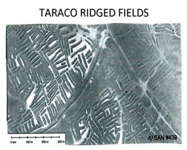
Figure 15 Constant y transect through D (Figure 5) of groundwater profile for dry season conditions.
Hydrologic Applications Exterior to City Precincts: Further Examples of Mastery of Groundwater Science
Research conducted on Tiwanaku’s raised field agricultural systems in the Pampa Koani region and systems under Tiwanaku influence on the northwest regions of Lake Titicaca has indicated use of advanced hydrological methodology underlying crop sustainability and yield improvement. Among the advances in agricultural science are uses of heat transfer technology to limit crop destruction by freezing during cold altiplano nights as well as hydrological/hydraulic control mechanisms providing groundwater height control to stabilize raised field swale water height through seasonal changes in water availability.19 Additionally, raised field technology has been shown the most appropriate design choice to limit short term drought effects on crop yield- this due to continual groundwater supply from intercepted rainfall over vast collection areas continually flowing to the Lake Titicaca basin. Analysis of ground water control mechanisms in the Pajiri agricultural area18,19 reveals different berm heights and swale depths appropriate to the needs of different crop types. All these observations point to an advanced agricultural science used to maximize and sustain crops in the Tiwanaku heartland In the Pampa Koani and northwest Tarraco regions of Lake Titicaca, different patterns of raised field lengths, widths and orientations are frequently inserted within more regular patterns- each pattern appropriate for the water needs of different crop types. Excavation of raised field berms in the Pampa Koani area has indicated stone base lining and clay layers to limit cold capillary water transfer from deep groundwater regions into berm interior regions; capillary water to the berm interior region is provided from swale water. Due to higher swale water temperatures from solar radiation input, the additional storage heat to berm interior regions limits convection and radiation heat withdrawal during cold altiplano nights to prevent freezing damage to crop root system. In other words, the latent heat removal for water to ice transition within berm interiors during cold altiplano nights is limited by additional heat transfer from elevated temperature swale water capillary heat transfer into berm interiors. Examination of Tarraco raised field berm patterns12 reveals an average berm shape consistency. Figure 16 shows that swales are interconnected leading to a continuous water path surrounding berms. When a typical berm is described as an elongated ellipse with major axis a and minor axis b, a-a and b-b in Figure 16, then a/b ratio from 10 to 12 appears to characterize average of berm geometries. This ratio for an elongated ellipse (a >> b) is significant in that the ellipse perimeter is a maximum for the given berm surface area (π a b) for this class of ellipse. This indicates that the average berm pattern configuration yields the maximum wetted berm perimeter and thus requires a minimum of interconnected swale lengths and widths and that narrower swale channels serve to provide capillary water transfer to narrow berms. Here the narrow berms (b << a) provide an easy path for elevated temperature capillary water to reach berm interiors. This, in turn, reduces the exposed water surface area of the interconnected swales reducing evaporation loss that helps to locally maintain a constant groundwater profile to maintain swale water height. The net effect is that a greater number of closely spaced berms can be watered properly per unit area to maintain the crop freezing defense while the greater area under cultivation produces more agricultural product for a given topographic area. These advantages are a key indicator of an advanced agricultural science being employed to protect and increase the yields of raised field agricultural systems. Thus the ab ratio of individual berms contains important information related to Tiwanaku engineering practice as their design incorporates a level of optimization to limit swale water area to reduce evaporation losses.
The conclusion that applies for the Tarraco raised field geometry also applies in the Pampa Koani region as Figure 17 indicates and makes similar claims of use the Terraco technology to maximize agricultural land area. Although regional differences may exist in raised field designs, the Tarraco system design may reflect different groundwater water availability and ambient air temperatures and crop types than those for Tiwanaku raised field designs that require more efficient use of water resources.
CFD results suggest that the drainage channel accelerated Tiwanaku’s ceremonial center and the surrounding urban areas dryness to greater depth throughout the year promoting the city’s ecological and hygienic benefits. For example, reduction of dampness in indoor habitable structures limits the occurrence of many respiratory and mould borne diseases. In the rainy season, the deep groundwater table upper boundary was stabilized by runoff and aquifer drainage into the drainage channel; in the dry season, additional seepage from the phreatic layer aquifer and canal M flow kept the deep groundwater upper boundary from subsiding. The resulting stabilization of the deep groundwater boundary prevented settling of monumental structures in the ceremonial core and originated from the design feature of the drainage channel’s depth intersection with the top fringe of the deep groundwater layer. This engineering innovation originated from knowledge of groundwater manipulation previously shown as vital to sustain Tiwanaku’s raised field agriculture.6,8 Channels P and Q largely served the hygienic requirements of the Putuni and Kerikala structures by providing continuous water flow from drainage channel seepage water and canal M water arriving into canal arm W. Each major monumental structure maintained an intricate drainage system that simultaneously served practical and symbolic purposes as exemplified by the Akapana’s elaborate drainage network that limited rainfall infiltration into its compartmentalized earth-fill interior to preserve its structural integrity. Canals O, N south of the drainage canal directed water to the qocha complex K for inter-city agricultural and pasturage purposes. Rainy season runoff water that washed into canals N, O and S exceeding their carrying capacity was diverted into canals L, I and J leading to the river thus protecting urban regions from canal overflow flooding. In totality, the drainage channel was the linchpin of an intricate hydraulic network that controlled surface and aquifer flows as rainfall amounts varied from rainy to dry seasons. Analysis of the canal’s hydrological function indicates that qocha systems were an integral feature of urban Tiwanaku. Interlinked by canals fed by Corocoro springs, qocha clusters K and C’ occupied massive portions of the city and likely supported camelid herds and caravans brought to the center during key social gatherings.29,30 Recent excavations in adjacent Mollo Kontu residential compounds support the hypothesis that llama and alpaca herds were important in this part of Tiwanaku38 and were served by K and C’ qocha pasturage areas. Raised-field and qocha systems that occupied the edges of some of the city’s canals are evident from aerial photos of the edges of canals I, J, L and C to support localized in-city agriculture and pasturage. The floodplain at the south edge of, and several meters below, the main portion of the city area of Tiwanaku supported an extensive cluster of integrated raised-field networks and qochas to support additional intra-city agriculture and pasturage.
Prior studies focused on Tiwanaku’s hinterland demonstrated an understanding of hydrologic principles to develop intensive raised-field farming systems. Present research indicates that the urban center of Tiwanaku incorporated an intricate hydrological network focused on the drainage channel that effectively managed seasonal water variations through surface canals, subsurface canals and aquifer drainage manipulation. CFD results detail many practical hydrological features of the drainage canal related to environmental and population livability concerns: these include rapid drying of subsurface soils underlying elite ceremonial and secular housing districts to limit soil dampness and its negative health effects on the city’s population. The drainage canal further supplied water to flush the subterranean canal network underlying the elite ceremonial core region to transfer human waste material to a nearby river. These health-related features are the first reported for any Andean pre-Columbian city. Tiwanaku city planners demonstrated an extraordinary level of knowledge regarding hydrologic and structural maintenance principles based upon surface and groundwater manipulation to maintain high livability standards under harsh altiplano environmental conditions. Building on prior studies of the groundwater-based raised-field systems that supported agriculture for the large population of Tiwanaku, analysis results demonstrate that knowledge of surface and groundwater flows within urban Tiwanaku merit further consideration in assessing New World engineering science.
None.
The author declares no conflict of interest.

©2016 rtloff. This is an open access article distributed under the terms of the, which permits unrestricted use, distribution, and build upon your work non-commercially.