MOJ
eISSN: 2576-4519


Review Article Volume 1 Issue 5
1Institute of Strength Physics and Materials Science SB RAS, Russia
2National Research Tomsk Polytechnic University, Russia
3Metal-Polymer Research Institute of NAS of Belarus, Russiaa
4Institute of SolidState Chemistry and Mechanochemistry SB RAS, Russia
Correspondence: Panin SV, Institute of Strength Physics and Materials Science SB RAS, Tomsk 634021, pr. Akademicheskii, Russia
Received: July 12, 2017 | Published: December 14, 2017
Citation: Panin SV, Shilko SV, Kornienko LA, et al. Biomechanical properties of dispersep article reinforced polymer composites on ultrahigh molecular weight polyethylene (UHMWPE). MOJ App Bio Biomech. 2017;1(5):192–199. DOI: 10.15406/mojabb.2017.01.00030
Biomechanical properties of composites based on UHMWPE and hybrid (polymer-polymeric) matrices “UHMWPE+PTFE” with disperse particle fillers were studied in order to develop materials for artificial joint implants. A comparative analysis of the efficiency on loading hydroxyapatite (HA) powder as biocompatible filler was performed. It was shown that wear rate of nano composites with the hybrid matrix is lower as compared with UHMWPE composites in conditions of dry friction and boundary lubrication. To optimize the composition of implant materials it is proposed to use the theory of dispersion hardening through the Mori-Tanaka model and Ilyushin function of plasticity as well as two-level method of computer-aided design. Comparison of calculation estimates by the developed technique with experimental data have shown that their relative error does not exceed 15%. Lowered values of the tensile strength of the nanoparticles filled composites is suggested to be due to lacking the interfacial layer consideration. Mechanical activation of powder components further enhances the durability of nano and micro composites almost doubling them without any substantial reduction in the strength properties. It is shown that wear resistance of nano- and micro composites with hybrid matrix under boundary lubrication is close to that at dry sliding friction.
Keywords: implants, biocompatible composites, ultrahigh molecular weight, polytetrafluoroethylene, hydroxyapatite, theory of dispersion hardening
HA, hydroxyapatite; PTFE, polytetrafluoroethylene; UHMWPE, ultrahigh molecular weight polyethylene; COF, coefficient of friction
Ultrahigh molecular weight polyethylene (UHMWPE) having a low coefficient of friction (COF), high wear- and chemical resistance in harsh environments, is used for fabricating medical products (hip and knee joints, intervertebral discs, plates for maxillofacial surgery, and others). Priority of polymers, in particular UHMWPE to be applied as medical implant materials, is due to their proximity to the biological tissues by physical and mechanical properties.1‒5 The book,6 which contains the most complete information on the use of UHMWPE in medical practice, is focused on improving tribological properties of UHMWPE by ionizing radiation treatment. The latter provides modification of either bulk material or a thin surface layer giving rise to increasing wear resistance of products. However, it significantly reduces the prosthesis ductility due to embrittlement (coming from cross linking). As a result, the larger number of wear particles and debris will be encapsulated in the joint area within a human body.7,8
UHMWPE nanocomposites filled with micro- and nano dispersed fillers are now actively exploring objects in medical materials science.9‒13 However, the discussions on loading nanoparticles into the implants made of UHMWPE is still controversial, and the choice of biocompatible fillers is extremely limited.13 Hydroxyapatite (C10 (PO4)6(OH)2) (GA) belongs to a class of biocompatible materials with high surface activity and is similar by its crystal structure to human bone tissue, providing strong fixation of implants. Along with hydroxyapatite, a bioinert polymer polytetrafluoroethylene (PTFE) possessing
May be used as solid lubricant filler in UHMWPE to fabricate advanced nano composites. Furthermore, the loading of PTFE enhances extrude ability of UHMWPE at manufacturing of medical products from composites that have previously been studied in Panin SV.15 Selection of optimal component composition for the composites was still done empirically, although the calculated (mesomechanical) methods do allow us to predict effective mechanical characteristics based on the parameters of the matrix and filler. The advantage of loading hydroxyapatite nanoparticles into the polymer consists in formation a porous nanostructure during subsequent resorption at operation of the prosthesis. In doing so, formation of nonporous framework besides maintaining the strength properties can give rise to synovial fluid accumulation in nonporous formed at the nanoparticles sites. This can provide effective lubrication by synovial fluid being partially released in the tribo contact zone of the polymer cup and metal (CoNiCr) prosthesis of hip head (much like in the case of a natural cartilage).16 This multiply reduces the wear rate of the polymer implant.1,2 Mechanical activation of the initial polymer components instead of high-energy beam (surface) treatment allows both to promote the interfacial adhesion and form a uniform structure over the bulk material enhancing mechanical and tribo technical properties. However, studies of UHMWPE composites for medical applications at employment the mechanical activation methods have not been described deep in the literature.
The biomechanical properties of the composites based on hybrid matrix "UHMWPE+PTFE" with hydroxyapatite nano- and micro particles were investigated in this paper. The technique for the calculation–based–prediction of strain and strength characteristics based on the parameters of the initial components with the estimate of the calculation accuracy is suggested. An aim of the study is to develop compositions and investigate the structure and properties of wear-resistant, biocompatible and extrude able composites based on ultrahigh molecular weight polyethylene for medical applications.
We used UHMWPE powder (Ticona, GUR-2122) with molecular weight of 4.0 million and average particle size of 5-15 microns; the polytetrafluoroethyleneF-4 PN20 powder (Æ14µm), nano- and micro particles of hydroxyapatite (C10(PO4)6(OH)2, Æ 20-30nm and Æ 7-8 microns, correspondently. Mechanical and tribological properties of the composites were studied under uniaxial tension, dry sliding friction and boundary lubrication. Samples of the composites were fabricated by is ostatic compression molding at the pressure of 10MPa and temperature 200°C with the subsequent cooling rate of 4°C/min. Stirring of the powder mixture of UHMWPE, PTFE and hydroxyl a patiteparticles was performed in a planetary ball mill MR/0.5*4 with preliminary dispersion of the components inan ultrasonic bath. Mechanical activation of mixtures was conducted in the ball mill AGO-2 at acceleration of 40G during one minute (the balls-to-powder mass ratio was 40:1).
Wear resistance of materials under dry sliding friction as well as boundary lubrication by distilled water was determined at "block-on-ring" scheme at the load of 68.8N per sample and the revolution rate of 100min-1(according to ASTM G99) on the friction testing machine 2078 SMT-1 (sliding velocity was 0.32m/s). The samples dimension was H×W×L=7×7×10mm. A diameter of counter body made of bearing steel was 62mm. The wear track surfaces of samples were examined by optical profile meter Zygo New View 6200. The wear tracks are was calculated with the help of «Rhino Ceros 3.0» software by manual selection of wear track contour and further automated calculations. Tribological characteristics were evaluated by averaging over four samples of each type.
Structural studies were carried out with the use of scanning electron microscope LEO EVO 50 at an accelerating voltage of 20kV. Cleavage surfaces of notched samples fractured mechanically after exposure in liquid nitrogen were observed. The degree of crystalline was estimated by combined DSC–TGA installation STD Q600. IR-spectra were recorded with the use of spectrometer NIKOLET5700. Mechanical properties of the materials were determined under tensile tests (according to RF National Standard GOST11262-80) with the help of electromechanical testing machine Instron 5582. The number of dog-bone shaped specimens for each material made at least 5.
As was noted above, the efficiency of the prosthetic materials development might be promoted by developing a calculation technique. The latter should make it possible to predict effective mechanical properties based on the parameters of the components (matrix and filler). As a result, composites can be designed with required (predetermined) characteristics. In this regard, the corresponding mechanical and mathematical model of the materials under study was developed along with the experimental study of the composites. The dispersed-filled UHMWPE considered in this study is macroscopically is otropicelastoplastic composite where volume fraction of the filler j does not exceed 8%. The value of j is associated with the mass fraction of the filler m by the following ratio
Here,and are the density of the matrix, filler and composite material, respectively.
Within this low range of filler volume fraction j the reasonably accurate calculation of effective elastic properties of the composite is provided by the Mori-Tanaka model.17 A configuration of isolated particles of the filler for materials under study is close to spherical one. In this case, according to the Mori-Tanaka model, effective shear modulus and effective bulk modulus of the composite are determined as follows
Here,and are the shear modulus of the material of the matrix and filler, respectively;and are the bulk modulus of the material of the matrix and filler, respectively. The Ilyushinplasticity function is commonly used for the description of the elastoplasticdeformation of materials. The deviator parts of the stress and strain tensors of the Ilyushin function are related by the following ratio
Here, eu is the intensity of the strain tensor; is the intensity of the strain tensor corresponding to yield point of the material; A, a are the parameters of the plasticity function. The values of mechanical properties of the components are presented in Table 1.18 Accounting for the plastic properties of the mineral filler for composites under consideration is not required. The shear module of the components should be replaced by the corresponding secantmoduli depending on the strain for description of the nonlinear deformation of the composite in (2).
In particular, at using physical equations (3) the secant modulus of shear of polymer components is a function of the shear angle for the given component
(4)
Use of there lations (2) involves analysis of the steps hear deformation of the composite at the description of the nonlinear deformation. A small increment of the macros copicshear angle for the composite is given at each step. The values of the secant modulus components are determined atones of shear angles in the components corresponding to the beginning of each step. A secant shear modulus of the composite at the beginning of a step is calculated by formulae (2). A step of the macroscopic shears tress is determined
Taking into account the strain concentrations,19 the step of the shear angle for each component is determined as
(6)
Further the values of the shear angles and macroscopic shear stress are re determined
(7)
Then the next step of the calculation is taken. . Corresponds to the matrix and to the filler in (7).
This procedure continues till the shear stress in the composite component reaches the critical value . Here is the ultimate strength of the corresponding component . The values of the macroscopic shear stress and shear angle , corresponding to the fracture onset of any components (the completion of the procedure is controlled by the steps hear deformation), allow us to determine the ultimate strength of the composite and value of longitudinal elongation at break
.
Note that in the second equation (8) the coefficient of transverse deformation of the material in plastic deformation range is close to 0.5. For the computer-aided design of implants made of disperse particle reinforced composites under consideration, it is reasonable to use two-level (micro- and macromechanical) calculation method described in paper.20
|
Material |
G, Mpa |
K, Mpa |
r, G/Sm3 |
eT, % |
A |
a |
sВ, Mpa |
|
PTFE |
90 |
4700 |
2.13 |
3,3 |
0.905 |
1.48 |
18.9 |
|
UHMWPE |
182 |
5058 |
0.93 |
5.1 |
0.984 |
1.04 |
32.5 |
|
HA |
3759 |
9804 |
3.11 |
- |
- |
- |
- |
Table 1 Characteristics ofbiocompatible matrixes and filler
The following optimum filler content for the PTFE and hydroxyapatite powders to be added into UHMWPE matrix was selected in this study based on the previously obtained data:10 wt.% F4, 0.5 wt.% HA(nano) and 20 wt.% HA(micro).11,14
Drysliding friction
Tribomechanical properties of
One can see from the table 1 that the Shore D hardness of the UHMWPE and“UHMWPE+10 wt.% PTFE” composites is slightly changed as compared to the neat polymer. The ultimate strength and value of elongation at break are constant, when the neat UHMWPE is filled with nanoparticles. However it is reduced at the loading of the hydroxyapatite micron size particles. The same result is observed at filling the hybrid matrix “UHMWPE+10 wt.% PTFE” with hydroxyapatite. The degree of crystalline for the composites with matrices of both types at loading the micron size particles decreases to a greater extent as compared to the nanoparticles. Tribological properties (wear rate, coefficient of friction) of composites depend strongly on the matrix type(basic or hybrid) and testing conditions(dry friction or boundary lubrication).The comparison of the calculation results at the use of equations(2)-(8) with the experimentally measured values σU andefor the composites under study is shown in Table 3. The technique of the “composite matrix” was employed at analysis of the three-componentcomposite comprisingUHMWPE, PTFE and HA. The characteristics of the polyethylenefilled with PTFE particleswere determined initially. Then these characteristics were used for the “matrix” material filled with the HA particles.
Note that the relative error does not exceed the theoretical estimates of 15%. The calculated values are within the experimental error range for the most composites. Underestimation of the ultimate strength for the material filled with nanoparticlesis most probably related to disregard of the interfacial layer21 in the model (2)-(8). It is required to derive more experimental data in order to check the proposed calculation technique in detail first of all in the view of the above named factor.
The analysis of kinetic wear diagrams for UHMWPE and "UHMWPE+10 wt.% PTFE" samples have shown that the wear rate of the latter is lower in contrast to the pure UHMWPE (Figure 1). The steady state wear intensities diagram (I, mm2/min) for the above matrices (columns 1, 4) as well as ones with the HA filler of different dimension (columns 2,3,5,6) are presented in Figure 2 It is seen from Figure 2, a that, firstly, the wear rate of the matrix"UHMWPE+10 wt.% PTFE" is 3 times lower than one of the neat UHMWPE. Secondly, the wear rate of the nano composite with 0.5 wt.% HA is close to that of the micro composite with 20 wt.% HA for the matrices of both type. Thirdly, mechanical activation of the powder components increases the wear resistance for both nano-and micro composites (almost doubles them -columns 7and 8). The wear track surface roughness in the micro composites is higher than that of the nanocomposites (Figure 2). The mechanical activation of the nanocomposite“UHMWPE+10 wt.% PTFE+0. 5% wt.% HA” (column 7) ensures the minimum wear rate as well as lowest wear surface roughness. Thus, mechanical activation of powder mixture components is an effective way to improve the wear resistance of the composites based on the hybrid matrix under drysliding friction. Filling the “basic” UHMWPE and the hybrid"UHMWPE+10 wt.% PTFE" matrices with the HA nano- and micro particles results in reduction of the friction coefficient (Table 2), wherein the mechanically activated nano composites possess the smallest CoF(0.083).
IR-spectra of the initial and activated compositions testify for the fact that new chemical bonds are not formed between the components of the mixtures during mechanical activation (Figure 3). Wear track surfaces as well as per molecular structure of composites based on the “basic” and the hybrid matrices with nano- and micro fillers (Figure 4) were studied. This was done to clarify the relationship between the wear patterns at the stage of steady state wear at drysliding friction with the structure formed at hot compression. It is seen that the wear track surfaces roughness in the composites with the hybridmatrix“UHMWPE+10 wt.% PTFE” is lower as compared with composites with the “basic” matrix. These data correlate well with their wear resistance (Figure 2B). The per molecular structure is kept spheruliticat filling UHMWPE with polytetrafluoroethylene powder up to its weight fraction not exceeding10 wt.% that is much like composites with the “basic” matrix (Figure 4). However, spherulites are not practically formed in the micro composites.
The mechanical activation of powder composition components results in more uniform distribution of the PTFE micro- and HA nanoparticles in the matrix. In doing so, more uniform fine spheruliticper molecular structure is formed. As a result, a uniform PTFE transfer film that provides increasing wear resistance and lowering friction coefficient is formed on the counter body. The fact of the PTFE transfer to the counter body is confirmed by the EDS micro analysis data of the counter body surface after drysliding friction tests.15
Friction at boundary lubrication
Results of tribotests at boundary lubrication (distilled water) indicates that the polytetrafluoroethylene retains its lubricating properties in these conditions as well. The wear kinetic curves (Figure 5a) and data on wear rate (Figure 5B) for the UHMWPE and composites with the “basic’ and the hybrid matrices at boundary lubrication are presented in Figure 5. It is seen that wear rate as decreased in both pure UHMWPE and its composites in contrast with dry sliding friction. Note, that wear rate is about of the same level for all the composites under study (columns 2-6). However, it is nearly twice as less for a mechanically activated nano composite with the hybrid matrix (column 7). Micrographs of the wear track surface for UHMWPE (Figure 6A) and “UHMWPE-PTFE” (Figure 6C) and their nanocomposites (Figure 6B) (Figure 6D) are presented in Figure 6A-D for the boundary lubrication sliding. It is seen that thin wear “micro scratches” (micro furrows) are characteristic for the pure UHMWPE wear track surface. Whereas they are absent in the specimens with the hybrid matrix and its nanocomposites. These testifies for the fact that PTFE acts as a solid lubricant during the wear process in the case of the hybrid matrix “UHMWPE+10 wt.% PTFE” both under dry sliding friction and at boundary lubrication. In doing so the transfer film should form on the counter body surface (being equivalent in effect to ultra disperse lubricating medium of nano fillers).
In our opinion, the high-energy mechanical activation of composition components provides more uniform distribution of fluorine particles as well as nano fillers in the matrix. This stimulates the rapid formation of a thin uniform transfer filmon the counter body even at the water boundary lubrication (Figure 5B). In so doing, the friction coefficient is also reduced (Table 2).
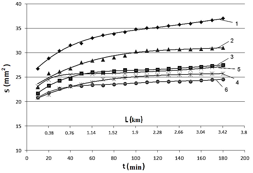
Figure 1
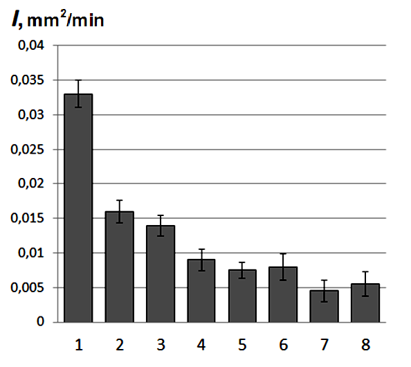
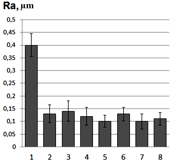
Figure 2 Wear rate (I) and roughness of friction track surface (Ra) UHMWPE
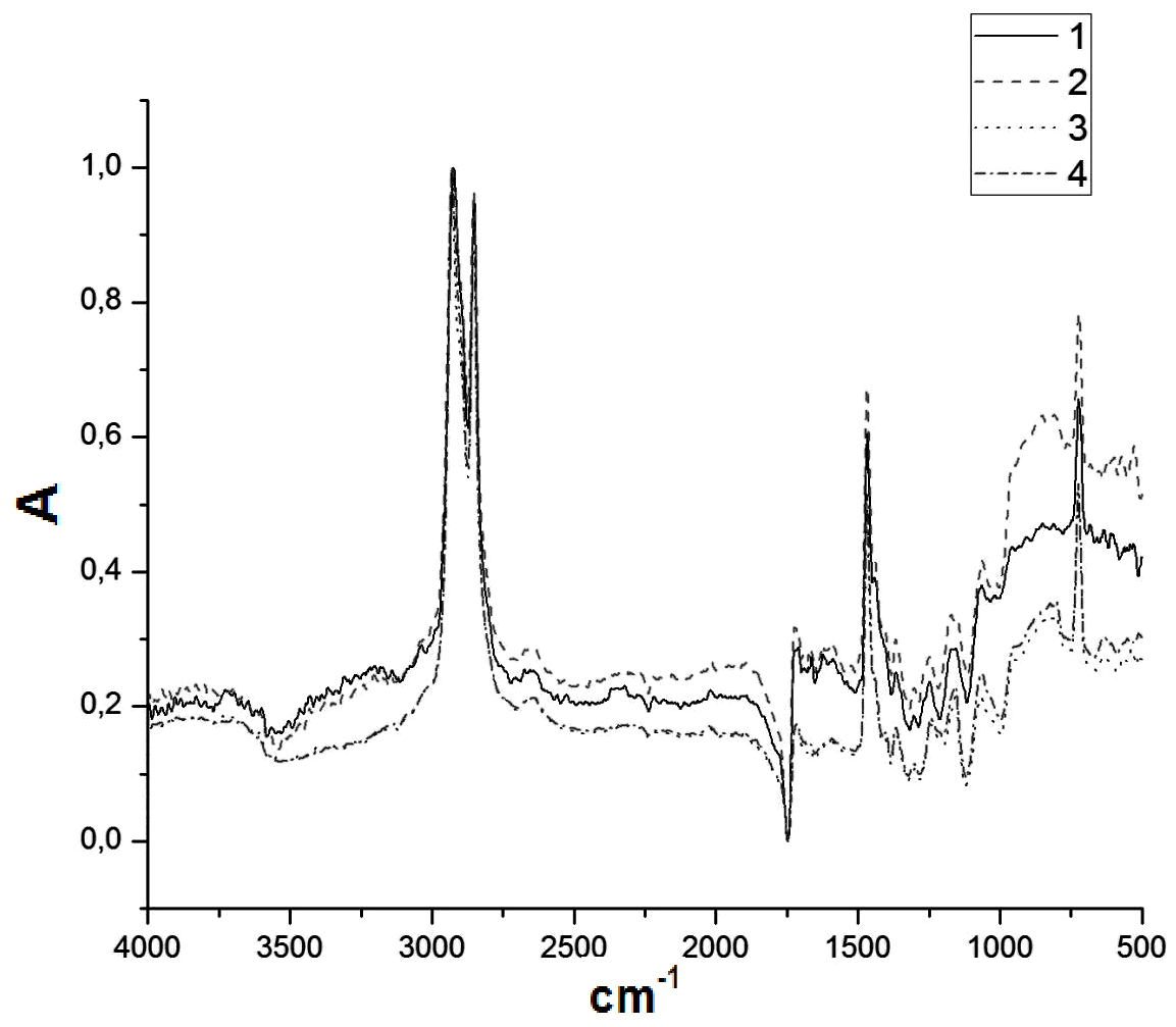
Figure 3 IRspectra of UHMWPE

Figure 4
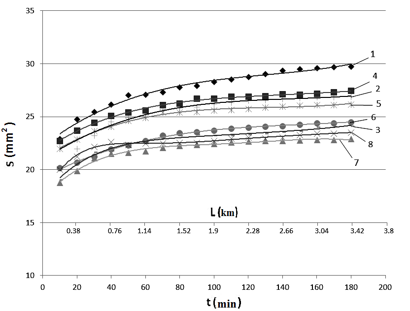
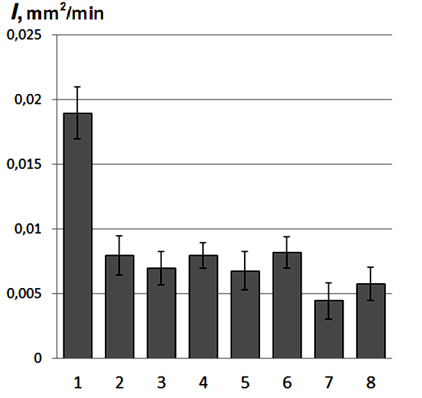
Figure 5 Kinetic wear diagrams (a) and wear rate (b) of UHMWPE
lubrication bydistilled water.

Figure 6 Micrographs of wear track surfaces UHMWPE
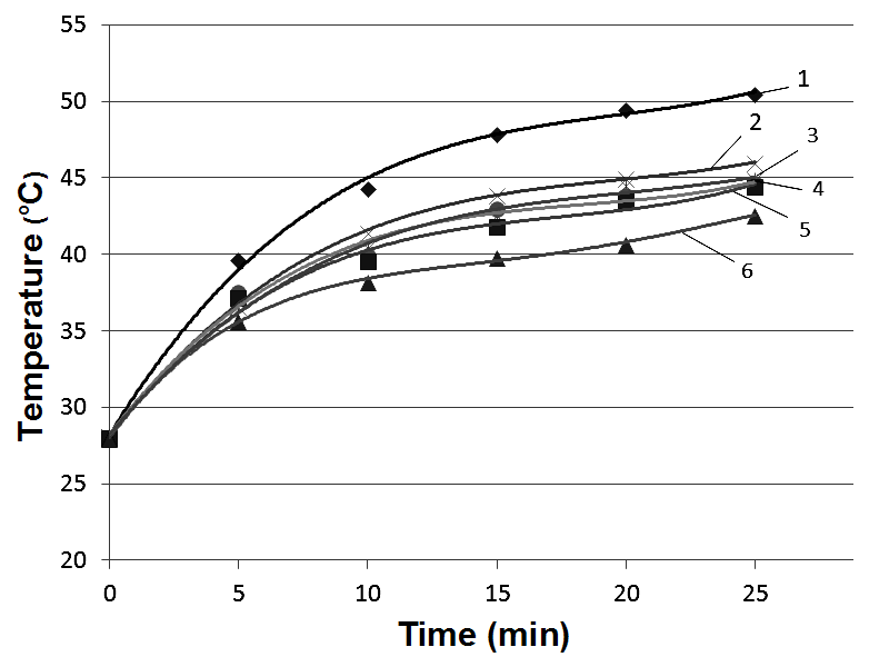
Figure 7
|
Filler content, Wt. % |
Density r, G/Cm3 |
Shored Hardness |
Ultimate Strength Σu, Mpa |
Elongation At Break Ε, % |
Crystallinity Χ, % |
Friction Coefficient ƒ |
|
|---|---|---|---|---|---|---|---|
|
Dry Friction |
Water Lubrication |
||||||
|
UHMWPE |
0.93 |
59.5±0.6 |
32.3±0.9 |
485±23.6 |
56.5 |
0.120 |
0.072 |
|
+0.5% HA (nano) |
0.93 |
59.2±0.5 |
32.4±0.9 |
481.9±22.6 |
40.2 |
0.096 |
0.055 |
|
+20 %HA (micro) |
1.07 |
58.9±0.5 |
25.8±0.9 |
433±23.1 |
32.0 |
0.098 |
0.068 |
|
UHMWPE+10%PTFE |
1.00 |
59.6±0.6 |
27.0±1.2 |
428±25.1 |
41.8 |
0.098 |
0.080 |
|
+0.5% HA (nano) |
0.99 |
58.8±0.5 |
26.5±0.8 |
423±23.0 |
38.1 |
0.093 |
0.067 |
|
+20% HA (micro) |
1.44 |
59.5±0.4 |
24.6±0.8 |
400±22.0 |
37.2 |
0.096 |
0.068 |
|
UHMWPE+10%PTFE+ Mechanical Activation |
0.92 |
58.5±0.6 |
33.5±1.2 |
435±22.1 |
42.1 |
0.085 |
0.067 |
|
+0.5% HA (nano) +Mechanical Activation |
0.99 |
57.1±0.6 |
26.2±0.9 |
305±21.3 |
37.2 |
0.083 |
0.068 |
|
+20 HA% (micro) +Mechanical Activation |
1.15 |
58.9±0.7 |
21.5±0.7 |
265.0±18.6 |
33.7 |
0.085 |
0.076 |
Table 2 Mechanical properties and friction coefficient of composites based on UHMWPE and “UHMWPE+10 wt.% PTFE” with various dimension of hydroxyapatite particles
The results presented in Table 3 testify for the validity of the developed mathematical model (2)-(8) for prediction of the effective characteristics of the composites under study. However, this model does not account for the effect of structure and properties modification of the composites at the mechanical activation. Improving this drawback of the calculated technique will be the matter of our future research.
The performed analysis of the tribotechnical characteristics of nano- and micro composites with UHMWPE and hybrid “UHMWPE+10 wt.% PTFE” matrices filled with the hydroxyl apatite testifies for the fact that polytetrafluoroethylene forms a uniform transfer filmon the counter body (polymer-polymer tribojunction) at the drysliding friction. This provides higher wear resistance of the both nano-and micro composites.15 The formed per molecular structure of the hybrid matrix nanocomposites is spherulitic one. It does not contribute substantially to the wear resistance of PTFE composites. The temperature on the wear track surface of nano- and micro composites also varies slightly as compared to the “basic ”UHMWPE matrix. Therefore, it does affect substantially the wear of the composites. This also testifies for the PTFE particles to act as solid lubricant inclusions in UHMWPE-matrix (Figure 7). In doing so the decisive importance in the wear resistance of the compositions with the hybrid matrix is related to PTFE adhesive layer formation at the counter body. This also confirms the increasing role of nano fillers as solid lubricant in the composites with “basic” UHMWPE matrix.
Comparative analysis of the tribotechnical characteristics of nano- and micro composites based on the UHMWPE and the hybrid “UHMWPE+10 wt. %PTFE” matrices filled with hydroxyapatite have shown that action of nano-sized HA as a solid lubricant medium is equivalent to adhesive PTFE transfer film formation under dry sliding friction.12,15 Loading of nano- and micro fillers into the hybrid matrix “UHMWPE+10 wt.% PTFE” increases slightly the wear resistance of the composite (Figure 2). Therefore, nano HA and PTFE can be interchangeably used at the development of the solid lubricating wear-resistant composites based on UHMWPE under dry sliding friction and boundary lubrication. Moreover polytetrafluoroethylene (with content less than 10 wt.%) is more efficient in comparison with hydroxyapatite in terms of wear resistant and friction coefficient (Figure 2) (Table 2).
|
m, % |
σU, MPa |
ε, % |
||
|---|---|---|---|---|
|
Experiment |
Theory |
Experiment |
Theory |
|
|
UHMWPE +0.5% HA (nano) |
32.4±0.9 |
30.1 |
481.9±22.6 |
466.1 |
|
UHMWPE +20 %HA (micro) |
25.8±0.9 |
25.2 |
433±23.1 |
440.9 |
|
UHMWPE +10%PTFE |
27.0±1.2 33.5±1.2* |
27.5 |
428±25.1 435±22.1* |
432.7 |
|
+0.5% HA (nano) |
26.5±0.8 26.2±0.9* |
25.2 |
423±23.0 305±21.3* |
402.3 |
|
+20% HA (micro) |
24.6±0.8 21.5±0.7* |
23.8 |
400±22.0 265.0±18.6* |
389.2 |
Table 3 Comparison of the calculated and experimental values of deformation and strength properties of the composites
*–after the mechanical activation.
It is shown that polytetrafluoroethylene particles act as also lid lubricant during wear of composites with the hybrid matrix “UHMWPE+10 wt.% PTFE” under drysliding friction and boundary lubrication. It is suggested that hydroxyapatite nanoparticles can be used for development of the biocompatible solid lubricanttttextrud able and wear-resistant composites based on UHMWPE and the hybrid matrix “UHMWPE+10 wt.% PTFE” in artificial joints for medical applications (for instance, for the implant manufacturing). It is demonstrated that high-energy treatment of powder components (matrix and fillers) by mechanical activation in a planetary ball mill provides an additional double increase in wear resistance. The demonstrated reasonable accuracy of predicting the effective strength properties of polymer composites studied in the paper allows us to further develop the Mori-Tanaka model in combination with the Ilyushinplasticity function and the procedure of shear step deformation. It is shown that for the computer-aided design of medical implants made of disperse particle reinforced composites studied in the paper the two-level (micro- and macromechanical) calculation method might be efficiently applied.
The work was performed as part of the program of basic fundamental research of the Russian (2013-2020) and Belorussian (2016-2020) Academies of Sciences. Partial financial support of RFBR and BRFBR is also acknowledged. Structural studies were partly carried out with the help of shared use center "Nanotech" (ISPMS SB RAS) and Analytical Center (National Research Tomsk Polytechnic University).
Authors declare that there is no conflict of interest.

©2017 Panin, et al. This is an open access article distributed under the terms of the, which permits unrestricted use, distribution, and build upon your work non-commercially.