International Journal of
eISSN: 2475-5559


Review Article Volume 5 Issue 1
1Southwest Petroleum University, China
2China Petroleum Engineering & Construction Corp North Company, China
Correspondence: Mingjun Du, State Key Laboratory of Oil and Gas Reservoor Geology and Exploitation, Southwest Petroleum University, Chendu, China
Received: June 27, 2020 | Published: August 10, 2020
Citation: Du M, Jing J, Zhang Z, et al. Study on drag reduction of annular heavy oil transport based on thin oil boundary layer. Int J Petrochem Sci Eng. 2020;5(1):40-47. DOI: 10.15406/ipcse.2020.05.00120
In this paper, thin oil is used as the boundary layer fluid to carry out the drag reduction experiment of heavyoil. The research shows that when the ratio of the thin oil reaches 45%~50%, the decrement of annular dilution pressure is nearly the same as that of the mixed dilution method, and the annular dilution pressure decreases rapidly with the increasing of dilution ratio; while the ratio reaches 65%,the annular dilution pressure drop is only 25% to 35% of the mixed dilution pressure drop.Fixed thin oil ratio to 50%,when the conveying temperature is higher than 55°C,the annular dilution pressure is lower than the mixed dilution pressure drop; when the ratio is 60%, the annular dilution pressuredrop is lower than the mixed dilution pressure drop in the whole test temperature range, which proves that the drag reduction effect is remarkable.
Keywords: flow boundary layer, heavy oil, thin oil, drag reduction, annular transportation
As the largest proven unconventional oil resource reserves in the world, the heavy oil has been widely concerned by scholars, especially with regard to viscosity reduction and drag reduction technology. With the change of the world energy pattern in recent years, the heavy oil resources in the offshore and alpine regions have become the focus of oilfield development in the future.At present, mature heavy oil transport technologies mainly include heating transport, diluting transport and emulsifying transport. Although traditional technologies have certain limitations in energy consumption and following treatment,1,2 these technologies are still effective means for heavy oil transportation before the new technology appears. Exploring the new technology of heavy oil transportation with safety, energy saving and low cost is an urgent practical problem to be solved at present.After nearly 40 years of continuous exploration, heavy oil drag reduction, which is based on the boundary layer theory, is still the focus and hotspot of scholars.3–7At present, the research of boundary layer drag reducing fluid mainly focuses on the aqueous ring and foam liquid ring. In the 1970s and 1980s, the technology of transporting heavy oil with water ring was presciently utilized by US, Soviet and Venezuela,8–10 and a number of field tests were carried out in China subsequently.11–13 Since the eccentricity of heavy oil transported by aqueous ring, scholars devote themselves to research the aqueous foam ring drag reduction technology according to the fact that flooding foam can increase oil production. Bricena et al.,14 provided the formula for calculating the thickness of foam liquid ring and its applicable scope by conducted a study on the flow characteristics of aqueous foam in a horizontal pipe.Dame et al.,15 made a study on the stability of foam. The results show that the dodecanol as surfactant added in SDS solution could improve the stability of foam. Jing et al.,16,17 devoted themselves to research of the drag reduction of aqueous foam, and developed oil-resistant and emulsified aqueous foam system based on the synergistic effect of surfactants. Although the stability of foam has been gradually improved with the continuous studies focus on the various foam systems by scholars, the problem of drainage is still unresolved, which also shows the direction for further research.
Based on the theory of the boundary layer, heavy oil drag reduction technology has made some progress at the stage of conceptual and experimental research,with lacking of a completed transport theory. It is still some distance to commercialization, and has many problems need to solve. For example: the phase change law of shutdown and restart process, the law of pressure drop change, the shutdown time, the stability of liquid ring under water hammer condition, the two phase stability problems of the big drop along the line, the problem of slug flow in the gas phase after the foam drainage, liquid ring repairing after the pump station, and so on. Massive heavy oil (Treated heavy oil) transportation mainly use the long-distance pipeline between the storage and transportation company and the refinery, which have strict requirements on the moisture content of heavy oil (not more than 0.5%). Consequently, the technologies of aqueous ring and aqueous foam liquid ring drag reduction have been limited in the application on the heavy oil pipeline. Dilution mixed reducing viscosity is the main method for long distance transportation of heavy oil, but it is badly needed to optimize the technology due to the large ratio of mixture, poor mixing effect and high transportation cost. This paper puts forward a new technology of heavy oil with ring dilution to reduce drag, based on the theory of flow boundary layer reducing drag. The technology uses thin oil as the boundary layer fluid to reduce the transmission resistance, the proportion of thin oil and the transport cost.
This project is proposed for the following two reasons:
Experimental device
In order to study the drag reduction characteristics of annular conveying, a simulation experimental device for boundary layer drag reduction was built. The device includes thin oil tank, heavy oil tank, mixing oil tank, thin oil pump, heavy oil pump, liquid ring generator, differential pressure transmitter and flowmeter, etc. The experimental process is shown in Figure 1. To make the distribution of the thin oil ring uniform and stable, a new type of liquid ring generator is designed by the author (Figure 2). The test section of simulation experiment is transparent tube with the diameter of D32 *3mm, and the length of pressure monitoring section is 1.0m. Owing to the effect of the color of heavy oil and thin oil (both black), low viscous silicone oil (milky white) and heavy oil (black) were used for experimental verification before verify the reliability of the annular flow, which attributes to their density are nearly same. After ensuring that the experimental device can form a stable liquid ring, heavy oil and thin oil annular conveying experiments will be carried out. Fig. 3 shows the flow pattern distribution of heavy oil and silicone oil under the conditions of 35%, 45%, 55% and 65% silicone oil injection ratio.
Figure 3 shows that the heavy oil always keeps flowing in the core area when the thin oil keeps flowing in the high shear zone near the pipe wall after injecting different proportions of thin oil. When the injection ratio of thin oil is low, the heavy oil presents a weak wave current. With the increase of injection ratio of thin oil, the heavy oil gradually presents uniform layered flow. Throughout the experimental process, the thin oil ring is very stable. It is feasible to carry out the experiment of heavy oil and thin oil annular transportation with this device.
In order to study the variation of pressure drop per unit pipe length and the drag reduction characteristics of thin oil under different injection ratio of thin oil to heavy oil, the drag reduction rate of the steady flow of light oil to heavy oil Δp is introduced to analyze the drag reduction effect. The calculation formula is as follows:
Dp=(DpH−DpR)'DpH100%
Where: Dp : Drag reduction rate; DpH : Pressure drop of unit pipe length in transportation with pure heavy oil, kPa ; DpR : Pressure drop of unit pipe length in transportation with thin oil ring, kPa .A comparative study of two conveying processes
In this paper, the experiment is carried out based on the actual transportation of oil products in an oil field. The instantaneous total flow rate of heavy oil and thin oil in the test section is 16L/min during the whole experimental process. The viscous temperature data of heavy oil and thin oil measured by RS3000 rheometer are shown in Table 1.
|
Temperatures ℃ |
40 |
45 |
50 |
55 |
60 |
65 |
70 |
75 |
80 |
|
Viscosity of Heavy Oil(mPa.s) |
15423.3 |
9154.2 |
5613.6 |
3667.5 |
2431.2 |
1701.3 |
1196.5 |
842.7 |
627.8 |
|
Viscosity of Thin Oil (mPa.s) |
9.35 |
7.68 |
6.37 |
5.18 |
4.62 |
4.08 |
3.65 |
3.24 |
2.9 |
Table 1 Dynamic viscosity data table of heavy oil and light oil at different temperatures
Figure 4 shows the relationship curves of pressure drop per unit length of thin oil ratio and drag reduction rate under three working conditions of oil temperature of 50 ~60 ~70 ~C, using annular conveying technology. In Figure 4, it can be seen that the pressure drop per unit pipe length decreases rapidly with the increase of the proportion of thin oil at different temperatures. When the proportion of thin oil is more than 55%, the pressure drop decreases slightly. From the corresponding drag reduction rate, the lower the oil temperature, the greater the drag reduction rate. This is mainly because the lower the temperature, the higher the viscosity of the base heavy oil, and the greater the pressure difference between annular transportation and pure heavy oil transportation. From the data, when the injection proportion of thin oil reaches 50% at different temperatures, the drag reduction rates of the three conditions are more than 95%. It further shows that the use of thin oil ring to transport heavy oil has very good drag reduction characteristics. Heavy oil and thin oil at 50, 60 and 70℃ are mixed in different proportions and stirred evenly. The viscosity of crude oil after mixing is shown respectively in Tables 2– 4.
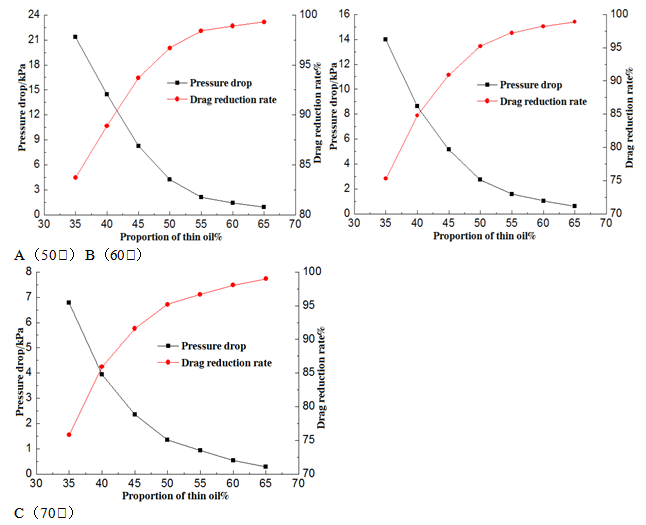
Figure 4 Curves of relationship between dilute oil ratio and pressure drop per unit length and drag reduction rate at different temperatures.
|
Proportion of thin oil % |
35 |
40 |
45 |
50 |
55 |
60 |
65 |
|
Mixed Viscosity (mPa.s) |
552.6 |
402.3 |
315.6 |
240.4 |
199.9 |
164.3 |
124.6 |
Table 2 Mixed viscosity data table of heavy oil mixed with different proportions of thin oil (50℃)
|
Proportion of thin oil % |
35 |
40 |
45 |
50 |
55 |
60 |
65 |
|
Mixed Viscosity (mPa.s) |
292.2 |
224.8 |
179.2 |
142.2 |
119.4 |
99.5 |
77.2 |
Table 3 Mixed viscosity data table of heavy oil mixed with different proportions of thin oil (60℃)
|
Proportion of thin oil % |
35 |
40 |
45 |
50 |
55 |
60 |
65 |
|
Mixed Viscosity (mPa.s) |
142.5 |
114.3 |
95.2 |
82.3 |
72.1 |
63.4 |
57.5 |
Table 4 Mixed viscosity data table of heavy oil mixed with different proportions of thin oil (70℃)
Figure 5 shows the change of the pressure drop per unit length vary with different proportions of thin oil for annular and mixed conveying processes at different temperatures. Table 5 shows the pressure drop data measured by the two conveying processes at different temperatures. From Figure 5 &Table 5, it can be seen that compared with traditional mixing and dilution drag reduction, the use of thin oil as boundary layer fluid, when the amount of thin oil is 45%-50%, the pressure drop of annular conveying is basically the same as that of mixed conveying at different temperatures. With the increase of thin oil ratio, the pressure drop of annular conveying decreases rapidly. When the amount of thin oil reaches 65%, the pressure drop of annular conveying is only 25%-35% of mixed conveying at different temperatures. The drag reduction effect is remarkable.Figure 6 shows the pressure drop curve of annular conveying unit pipe length at different temperatures as function of different proportion of thin oil. According to Table 1, the difference of heavy oil viscosity is apparent at different temperatures when the thin oil viscosity enjoys a slight change. In the annular transportation process, pressure drop per unit length decreases rapidly with the increase of oil temperature and injection volume. When the proportion of thin oil exceeds 55%, the pressure drop per unit length decreases at different temperatures. This is mainly due to the fact that with the increase of the proportion of thin oil, when the thickness of the boundary layer reaches a certain value, the velocity gradient between the inner layers and layers of the heavy oil in the core area decreases, the internal friction force decreases, and the heavy oil is suspended in the form of rigid body in the form of low viscous thin oil. At this time, the pressure drop of the pipeline mainly caused by the thin oil, especially the viscous difference between the thin oil and the heavy oil is greater.
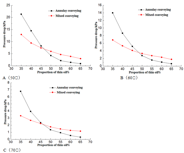
Figure 5 Pressure drop comparison of unit pipe length with different proportion of thin oil in two transportation processes.
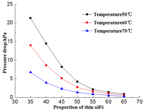
Figure 6 Variation curve of pressure drop per unit pipe length of annular conveyor at different temperatures.
|
Proportion of thin oil % |
Pressure drop per unit length at 50℃, kPa |
Pressure drop per unit length at 60℃, kPa |
Pressure drop per unit length at 70℃, kPa |
|||
|
Annular conveying |
Mixed conveying |
Annular conveying |
Mixed conveying |
Annular conveying |
Mixed conveying |
|
|
35 |
21.34 |
12.94 |
14.02 |
6.85 |
6.78 |
3.33 |
|
40 |
14.49 |
9.42 |
8.62 |
5.3 |
3.94 |
2.68 |
|
45 |
8.23 |
7.41 |
5.16 |
4.12 |
2.36 |
2.23 |
|
50 |
4.23 |
5.96 |
2.74 |
3.31 |
1.35 |
1.76 |
|
55 |
2.14 |
4.67 |
1.58 |
2.74 |
0.93 |
1.46 |
|
60 |
1.44 |
3.87 |
1.05 |
2.31 |
0.54 |
1.26 |
|
65 |
0.91 |
2.91 |
0.62 |
1.76 |
0.29 |
1.16 |
Table 5 Comparisons of pressure drop of two transportation process at different temperatures and different ratio of thin oil
Adaptability analysis of circular conveying process
At present, the heavy oil transport is usually mixed with 50 % to 65 % of the dilute oil (depending on the viscosity of heavy oil determined). With the continuous development of heavy oil resources, the consumption of dilute oil increased. The problem for flow protection of dilute oil is becoming more and more serious. In the previous study, it has been clear that drop of pressure for the circular conveying is much lower than drop of pressure for the mixed dilute transport when the dilute oil ratio exceeds 50%. Considering that there is a certain temperature drop in heavy oil during the conveying of long distance. That is to say, the viscosity of oil in the pipeline will increase with the decrease of temperature during the conveying process. Therefore, studying the variation of pressure drop in circular and mixed conveying at different temperatures, can provide the necessary basis for the feasibility of long-distance circular conveying of heavy oil, and further verify the feasibility of the circular low temperature conveying of heavy oil.
In the experiment, 50% and 60% of injection of the conventional dilute oil were tested, which usually used in the oil field. The viscosity-temperature data of mixed oil at different temperatures is shown in Table 6. The viscosity-temperature curve of the corresponding mixed oil is shown in Figure 7. From Figure 7, it shown that the viscosity of mixed oil decreases significantly with the increase of the temperature of mixed oil after adding different proportion of dilute oil. However, the viscosity difference between the two types of working conditions becoming gradually smaller with the increase of temperature. When the temperature of mixed oil rises to 80℃, the viscosity difference between the mixed with 50 % dilute oil and 60 % dilute oil is only 10 mPa (Table 6). It is further shown that the resistance reduction characteristics of dilute oil is weakened in the actual mixing process.
|
Temperature ℃ |
40 |
45 |
50 |
55 |
60 |
65 |
70 |
75 |
80 |
|
The viscosity of 50% dilute oil(mPa.s) |
443.4 |
323.3 |
240.4 |
182.4 |
142.2 |
112.3 |
82.3 |
62.4 |
48.2 |
|
The viscosity of 60% dilute oil(mPa.s) |
288.6 |
215.2 |
164.3 |
126.3 |
99.5 |
78.2 |
63.4 |
50.1 |
38.3 |
Table 6 Dynamic viscosity at different temperature after mix heavy oil with dilute oil (mPa.s)
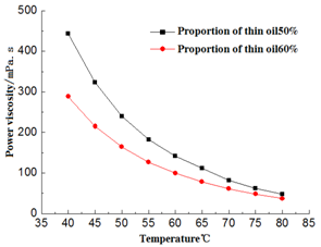
Figure 7 The viscous temperature curves of mixed 50 % and 60 % dilute oil at different temperatures.
Form Figure 8, it shows the comparison curves of pressure drop of two dilute oil ratios and two conveying processes at different temperatures. Table 7 shows the corresponding experimental test data.According to the analysis in Figure 8 and Table 7, it can be seen that pressure drop of the circular conveying is lower than that of the mixed conveying when conveying temperature between 55℃ to 80℃ and the proportion of dilute oil injected is 50%. When the injection ratio of dilute oil is 60%, pressure drop of the circular conveying is lower than that of the mixed conveying in the whole test temperature range(40℃~80℃). Therefore, in the long-distance circular conveying of heavy oil, it is necessary to confirm a reasonable inlet oil temperature to ensure the pressure drop of the whole pipeline is lower than that of the mixed conveying, and energy conservation is achieved. Simultaneously, the energy conservation and consumption reduction can be realized by reducing the circular conveying temperature when the pressure drop of whole pipeline is certain.The difference between the dilute oil circular and the water circular is that the viscosity of the mixing zone of the dilute oil and the heavy oil reduced in the process of conveying, while the viscosity of the mixing zone of the water and the heavy oil increased after emulsification. So, there is no need to worry about the interfacial mixing of the heavy oil and the thin oil. In fact, because of the mixing of the dilute oil and the heavy oil is insufficient, the sample of heavy oil and dilute oil is still separated after long-distance conveying. In the pipeline conveying process, dilute oil is used as boundary layer fluid without external force (stirring, etc.) and dilute oil and heavy oil will maintain a certain spatial stability. The mixed interface of two-phase is limited, thin oil can effectively play the role of boundary layer drag reduction.
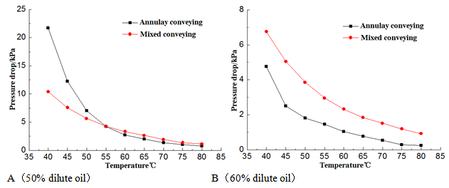
Figure 8 The comparison curves of pressure drop between two conveying processes at different temperatures.
|
Temperature ℃ |
The ratio of dilute oil is 50% |
The ratio of dilute oil is 60% |
||
|
The pressure difference of circular conveying kPa |
The pressure difference of mixed conveying kPa |
The pressure difference of circular conveying kPa |
The pressure difference of mixed conveying kPa |
|
|
40 |
21.71 |
10.39 |
4.76 |
6.75 |
|
45 |
12.26 |
7.57 |
2.51 |
5.04 |
|
50 |
7.03 |
5.63 |
1.82 |
3.85 |
|
55 |
4.22 |
4.27 |
1.45 |
2.95 |
|
60 |
2.73 |
3.33 |
1.04 |
2.32 |
|
65 |
1.97 |
2.64 |
0.76 |
1.84 |
|
70 |
1.35 |
1.93 |
0.54 |
1.51 |
|
75 |
1.06 |
1.35 |
0.29 |
1.19 |
|
80 |
0.76 |
1.13 |
0.24 |
0.92 |
Table 7 Pressure drop for circular conveying and mixed conveying of unit length at different temperatures
Because of the density difference between dilute oil and heavy oil, it is inevitable that eccentric (lower eccentric) flow occurs during long distance conveying. The research results of heavy oil water circular conveying can be used for reference. By analyzing the density difference, viscosity difference, velocity difference, liquid circular thickness and pipeline length of heavy oil and dilute oil, the mechanical model of stable liquid circular conveying is constructed, and the boundary of stable transportation of eccentric liquid ring is given, so as to reduce the risk of conveying.
At present, most scholars only study the drag reduction rate and stability of drag reduction fluid and pure heavy oil conveying process in drag reduction technology of boundary layer fluid. But do not compare with the actual application of heavy oil conveying technology in engineering, which leads to the unclear definition of technical advantages and application scope. In this paper, the following conclusions are drawn through the experimental comparison between circular conveying and mixed dilution conveying.
The authors wish to thank the National Natural Science Foundation of China (Grant No. 51779212) and National Science & Technology Major Project of China (Grant No. 2016ZX05025004-005).
There are no conflicts of interest.
None.

©2020 Du, et al. This is an open access article distributed under the terms of the, which permits unrestricted use, distribution, and build upon your work non-commercially.