International Journal of
eISSN: 2475-5559


Mini Review Volume 4 Issue 1
Moscow State University, Moscow 119991, Russian Federation, Russia
Correspondence: Korotkov Yu F, Moscow State University, Moscow 119991, Russian Federation, Russia
Received: May 29, 2017 | Published: February 28, 2019
Citation: Korotkov YF, Kuznetsova MG, Larionov VM, et al. Environmental protection from associated petroleum gas emissions in oil and gas industries. Int J Petrochem Sci Eng. 2019;4(1):38?39. DOI: 10.15406/ipcse.2019.04.00100
The article deals with measures to protect the environment from gas emissions from oil and gas pipelines on gazoneftepromyslah gusts. Described gasdynamic igniter for ignition at abnormally discharged flare gas installations.
Keywords: environment, oil gas flare
Environmental protection from associated gas emissions on oil and gas fields Increasing every year the volume of products produced on land and offshore are doing to protect the environmental problem from gazoneftevybrosov all the more urgent. Preparation of oil products presenting themselves, most often, a mixture of APG formation water and oil, is produced in the sealed joint collection systems, processing and transport.1 The separated in these systems from the droplet associated gas is transported by pipeline to gas processing plants. To eliminate contamination of the environment with gusts petroleum gas pipelines it is burned in flares.2,3 The main equipment is headroom flares and flare ignition and control system. Ignition solves the problem of safe and reliable burning torch, and a control system - tracking the presence and behavior of a flame, and also qualitative (smokeless) of the combustible mixture combustion. JSC "TatNIIneftemash" put the party flares for use in areas with harsh climatic conditions. By comparison with previous designs, these units have the following basic structural features and the technical and economic advantages:
torch tip design allows high quality combustion gas with changing performance flare;
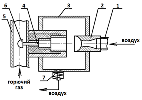
Some of the indicators developed in a number of "TatNIIneftemash" models of flares are shown in Table 1.4 The most simple, reliable and safe method to set fire emergency flares discharged APG include gasdynamic inflammation. Figure 1 shows a gas-dynamic igniter,5 wherein the working medium is air. The resonance tube is a multistage, wherein the diameter of each subsequent portion toward fuel delivery pipe diameter smaller than the previous section. The end of the tube is placed in the fuel supply pipe and configured plugged. Air under pressure is supplied to the pipe 1 passes the nozzle orifice 2 and enters into an acoustic chamber 3, and through it - to the resonance tube 4. The interaction of the air stream flowing at a high velocity from the nozzle head to the acoustic chamber, with an oscillating gas in the resonance tube column leads rise to resonance of the acoustic oscillations. These oscillations are accompanied by the air flowing in and out in the resonance tube, which causes propagation of shock waves therein. Periodic oscillations of large amplitude velocity of the gas cause muffled heating end of the tube to a temperature of about 1000◦S. The radiator 6 is formed as a part of the umbrella and fuel gas in the fuel supply pipe enters the cavity of the umbrella, in which the flow movement is slowed down, thereby increasing the contact time of the fuel gas with very hot emitter. Contacting the emitter combustible gas ignited, burned and the flame at the outlet of the fuel supply tube ignites the combustible gas mixture moving along the main pipeline. Check valve 7 on an acoustic chamber remains in the closed position, preventing the cavity chamber and a resonance tube from the external environment. The air discharged from the acoustic chamber through a check valve to the atmosphere. JSC "TatNIIneftemash" The following problems were solved in the design headroom for flares:
Indicators |
Model |
||||
UV-200-CL |
UV-300-CL |
UV-500-CL |
UV-800-CL |
UV-1000-CL |
|
One |
2 |
3 |
four |
five |
6 |
Throughput of petroleum gas, m3/h |
9000 |
20000 |
56000 |
144000 |
226000 |
The gas pressure in the pilot burners, MPa |
0.3-0.8 |
||||
Conventional diameter flare stem, mm |
200 |
300 |
500 |
800 |
1000 |
Torch Height, m |
20 |
20 |
25 |
thirty |
35 |
The number of pilot burners and to the ignition control system |
2 |
2 |
2 |
four |
four |
ignition and control system |
Electrical |
Table 1 Some of the indicators developed in a number of "TatNIIneftemash" models of flares

Figure 1 Gas dynamical igniters.
1, Air supply pipe; 2, the nozzle orifice; 3, acoustic chamber; 4, resonance tube; 5, fuel supply pipe; 6, emitter; 7, return valve.
The problem of utilization of the combustion products associated gas and combustion heat from it to gazoneftepromyslah remains hitherto unsolved.
Findings
None.
The author declares that there are no conflicts of interest.

©2019 Korotkov, et al. This is an open access article distributed under the terms of the, which permits unrestricted use, distribution, and build upon your work non-commercially.