International Journal of
eISSN: 2475-5559


Research Article Volume 2 Issue 5
1Department of Petroleum Engineering, Petroleum University of Technology, Iran
1Department of Petroleum Engineering, Petroleum University of Technology, Iran
Correspondence: Ghassem Alaskari MK, Department of Petroleum Engineering, Petroleum University of Technology, Iran
Received: February 01, 2017 | Published: June 27, 2017
Citation: Ghassem AMK, Roozmeh A. Determination of shale types using well logs. Int J Petrochem Sci Eng. 2017;2(5):160-166. DOI: 10.15406/ipcse.2017.02.00051
Determination of shale type in shale formation has long been a difficult task. Presence of shales in some of the Iranian reservoir formations are one of the most important subject. Shale types have to be considered, because existence of shale type reduces, effective porosity and permeability of the reservoir to some extent. Allogenic Shale is distributed in formations in three basic types, Dispersed, Laminar and structural. Each of these shale types has different effect on porosity, permeability and water saturation. Dispersed shale type reduces effective porosity and permeability to a great extent, but, laminar and structural have less effect on petrophysical parameters. In this investigation, shale types, Shale volume and effective porosity of shale formations have been determined from well logs based on cross-plotting. In other words, a triangle Density-Neutron cross-plot is used to determine the above parameters. The area of study chosen from central oil fields of Iran, where some of the wells are used (Tabnak Field). Tabnak Well C selected for this study in Kangan Formation, South Pars. This study illustrates that distribution of shale types in Kangan Formation is mainly dispersed shale with few of laminar shale, and the quality of effective porosity (φe) decreases with increasing depth in the Kangan Formation.
Keywords: shaley formation, shale types, cross-plotting, kangan formation, well logs
Shale is a fine-grained sedimentary rock usually composed of 50% silt (3.9-62.5μm), 35% clay (0.98-3.9μm) and 15% other fine clastic particles (feldspars, quartz, carbonates, zircon, etc.). Shale is distributed in reservoir formations in three basic types, structural, laminar, dispersed or combination of these three types. Each type of shale is described as given in Ghorab.1
Structural shale
Exists in the form of fragments or crystals which are an integral part of the rock framework. In other words, is considered as a portion of rock matrix. This mode of shale distribution has no effect on porosity or permeability.2
Laminar shale
Exists as layer of clay minerals within clean formations (i.e. sandstone, carbonate, etc). The effect of this type on porosity and permeability is sometimes severe and should be investigated.
Dispersed shale
Dispersed shale is composed of clay minerals, fragments or crystals which usually found on grain surface, occupying pore spaces between particles. Dispersed shale will include both detritus and diagenetic clay minerals. One or both of these forms may be present in this type shale. This type of shale reduces effective porosity and permeability to a great extent.
Considerable portion of shale consists of clay minerals such as illite, kaolinite, chlorite, montmorillonite, and etc. Clay minerals in reservoir formation have severe effects on petrophysical properties and reduce the effective and total porosities as well as permeability of the reservoir. Also, shale causes serious problems in formation evaluation and drilling operations.3
Shale affects all well logging measurements to some degree.4 With using well logging data, presence of shale in a formation can be recognized. Besides, shale types, shale volume and effective porosity can be determined either graphically (Cross-plotting) or analytically using Gamma ray spectrum (CGR).
In this investigation, Vsh estimated from cross-plot method is compared with Vsh calculated from Gamma ray spectrum (CGR).
Shale volume (Vsh) calculated from gamma ray spectrum
In this paper, Vsh estimated from cross-plot method is validated with Vsh calculated from Gamma ray spectrum (CGR). CGR is the best and most accurate method for determining shale volume. The following equations are used to calculate shale volume.
IGR=CGRlog−CGRminCGRmax−CGRmin, CGR=Alogth+BLogKIGR=CGRlog−CGRminCGRmax−CGRmin, CGR=Alogth+BLogK
Then, the shale volume (Vsh) can be calculated from the Gamma ray index, by the following formula;
Vsh = 0.33[2(2×IGR)-1.0] for hard formation ………… (2)
Vsh =0.083[2(3.7×IGR)-1.0] for soft formation …………. (3)
Vsh =IGR / [3-2IGR] for gas saturated formation [4]……….(4)
Hydrocarbon correction
More accurate method to correct for hydrocarbon effect on density and neutron porosities before points are plotted on cross-plot are given below:6
For the neutron porosity
φNcorr= φN– ΔφN ……………… (5)
Where
ΔφN=φShrρh−0.7+0.4P1−0.4P
For oil…………. (6)
ΔφN=φShr2.2ρh−0.7+0.4P1−0.4P
For gas …………… (7)
In fresh mud (less than 50000 ppm) the equation can be reduced to:
ΔφN=φShr(ρh−0.7)
ΔφN=φShr(2.2.ρh−1.0)
for gas…………. (9)
and
Pis salinity of the mud in PPM
φN is neutron porosity
φNcorr is corrected neutron porosity
ρhis hydrocarbon density
Shris residual oil saturation
For the density porosity
φdcorr=φd−Δφd ………. (10)
Where,
φd= (ρma−ρb)/(ρma−ρf)
…………… (11)
Δφd= 1.07φShr(1.11(1−ρh)+0.65P−0.03)ρma−1.0−0.7P
…for oil…….. (12)
Δφd= 1.07φShr1.11−0.65P−1.24ρhρma−1.0−0.7P
… for gas…… (13)
In salinity less than 50000 ppm (fresh mud) the parameter, P can be considered zero. An estimation of hydrocarbon density ρh can be obtained by the following equations.
ρh=0.7×(1+φnφd)Shr−(1−φnφd)(1+0.72φnφd)Shr
for oil saturated………. (14)
ρh=(1+0.72φnφd)Shr−(1−φnφd)(2.2+0.8φnφd)Shr
for gas saturated……….(15)
Residual hydrocarbon saturation is used, because the neutron and density tools investigate the flushed zone. The saturation in the flushed zone is calculated based on the Archie’s equation.
Sxo=√(aφm×RmfRxo) =√FRmfRxo and Shr= 1−Sxo ……………… (16)
φis porosity of the formation
m is cementation factor
a is lithology constant
Rmf is resistivity of mud filtrate
Rxois resistivity of flushed zone (micro resistivity tool response)
Shale volume (Vsh) Estimated from cross-plot (CP)
Generally, cross-plot is a quick and commodious method for estimation of shale volume and shale types with acceptable accuracy in comparison with other methods, such as core and log analysis.7 XRD is one the exact methods for clay mineral determination.8
In this cross-plot three distinct points (F, M, SH) are shown Figure 1. Point F represents fluid or water point, where φD= φN=100%. Point M represents matrix point. If density and neutron tools are calibrated in term of the existing matrix, then φN= φD=0. Point SH represents shale point. The coordinate of point SH [φNSh , φDSh] must be determined for shaley portion of well and this coordinate vary from well to well and have to be estimated for each case.9
Effective Porosity (φe) estimated from cross-plot (CP)
Line M-F represents clean formation or Vsh=0 line. This line is scaled in effective porosity as shown in Figure 1. Points representing φNand φDvalues in clean formations will fall on M-F line and their position on the line indicate effective porosity values. Line M-SH represents φe=0 line and value of each point on this line indicates shale volume of the formation that has no effective porosity. Points that represent shaley formation fall within triangle. Because porosity values do not exceed 50%, line M-F is plotted till 50% porosity to make full use of cross-plot.10 Following equations have been used to construct this triangle.
φe= φn− (φNSh. Vsh), φe= φd − (φDsh. Vsh) ………………… (17)
In Figure 1 laminar shale points fall on LAM or around LS-SH line, dispersed shale points fall on or around DIS line and structural shale point’s fall on or around STR line.
For each point within triangle Vsh is estimated on M-SH line parallel to clean formation line (diagonal line), and also, φeis determined on clean formation line parallel to M-Sh line. For example point A in Figure 1 represents a shaley formation that has values of φe= 9% and Vsh = 23%. Shale type for this point is dispersed.11
If formation contains hydrocarbon, Neutron and Density porosities have to be corrected before points are plotted, by using the equations (4-17).
There are five depths interval selected for this study from Kangan Formation, well-C Figure 2. The results for each interval have been given below.
Depth intervals “2590-2592m”
This interval of formation has considerable volume of shale and saturated with formation water Figure 3. After plotting measured points of this interval on cross-plot Figure 4 is seen that aggregation of points is around laminar shale line. So, distribution mode of shale for this section of formation is laminar. Vsh and φeestimated from cross-plot for each point of this interval are given in Table 1.
PHI-N |
PHI-D |
PHIE-CP |
Vsh -CP |
0.424 |
0.122 |
0.051 |
0.88 |
0.417 |
0.133 |
0.067 |
0.83 |
0.407 |
0.141 |
0.079 |
0.78 |
0.395 |
0.145 |
0.085 |
0.73 |
0.375 |
0.144 |
0.09 |
0.67 |
0.367 |
0.141 |
0.088 |
0.66 |
0.35 |
0.137 |
0.088 |
0.62 |
0.339 |
0.133 |
0.085 |
0.6 |
0.328 |
0.128 |
0.081 |
0.58 |
0.315 |
0.123 |
0.087 |
0.56 |
0.309 |
0.119 |
0.074 |
0.56 |
0.317 |
0.117 |
0.07 |
0.58 |
0.335 |
0.12 |
0.069 |
0.63 |
0.355 |
0.127 |
0.074 |
0.67 |
0.374 |
0.138 |
0.082 |
0.69 |
0.384 |
0.148 |
0.092 |
0.69 |
0.387 |
0.153 |
0.098 |
0.68 |
0.379 |
0.152 |
0.098 |
0.67 |
0.373 |
0.144 |
0.091 |
0.67 |
0.371 |
0.134 |
0.078 |
0.69 |
0.365 |
0.125 |
0.067 |
0.71 |
Table 1: Vsh and PHIE (φe) estimated from cross-plot (CP) for depth interval 2590-2592m.
Depth intervals “2650.3-2652”
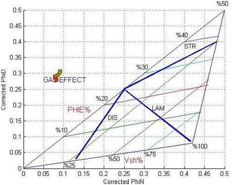
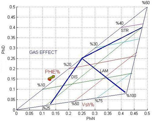
This section has no shale and there is gas in formation Figure 5. So, neutron and density porosities must be corrected for hydrocarbon effect. Figures 6 & 7 shown positions of points before and after correcting hydrocarbon effect for neutron and density porosities on cross-plot and is seen that points fall on clean formation line after hydrocarbon correction. For this interval, φeestimated from cross-plot, corresponds to 15.2 to 16.8 % Table 2 and effective porosity measured with core analysis method is 17.1 to 18.2%. As one can be seen, this result is very close together, and therefore, this method can be applied to estimate effective porosity with acceptable accuracy. Vsh and φedetermined from cross-plot for each point of this interval are given in Table 2.

Figure 6: Neutron-Density porosity cross-plot for 2650.3-2652m depth interval (before gas correction).

Figure 7: Neutron-density porosity cross-plot for 2650.3-2652m depth interval (after gas correction).
PHIN-COR |
PHID-COR |
PHIE-CP |
Vsh -CP |
0.127 |
0.147 |
0.152 |
0 |
0.127 |
0.148 |
0.152 |
0 |
0.128 |
0.148 |
0.153 |
0 |
0.127 |
0.149 |
0.153 |
0 |
0.126 |
0.149 |
0.154 |
0 |
0.125 |
0.15 |
0.155 |
0 |
0.124 |
0.15 |
0. 156 |
0 |
0.124 |
0.15 |
0.156 |
0 |
0.125 |
0.151 |
0.157 |
0 |
0.127 |
0.152 |
0.158 |
0 |
0.13 |
0.153 |
0.159 |
0 |
0.134 |
0.156 |
0.161 |
0 |
0.138 |
0.159 |
0.164 |
0 |
0.141 |
0.162 |
0.167 |
0 |
0.142 |
0.163 |
0.168 |
0 |
Table 2: Vsh and PHIE (φe) estimated from cross-plot (CP) for depth interval 2650.3-2652m.
Depth intervals “2718.5-2719.5m”
This interval of formation has intermediate volume of shale and saturated with formation water Figure 8. After plotting measured points of this interval on cross-plot Figure 9 we seen that points occupy the area between laminar and dispersed shale lines. So, distribution mode of shale for this section of formation is combination of laminar and dispersed types. Vsh and φe estimated from cross-plot for each point of this interval and are given in Table 3.
Depth |
PHI-N |
PHI-D |
PHIE |
Vsh -CP |
VSH-CGR |
2718.5 |
0.272 |
0.065 |
0.017 |
0.607 |
0.557 |
2718.6 |
0.274 |
0.072 |
0.024 |
0.595 |
0.604 |
2718.7 |
0.272 |
0.077 |
0.031 |
0.574 |
0.620 |
2718.8 |
0.264 |
0.079 |
0.036 |
0.545 |
0.593 |
2718.9 |
0.254 |
0.079 |
0.038 |
0.513 |
0.534 |
2719.0 |
0.244 |
0.077 |
0.038 |
0.489 |
0.466 |
2719.1 |
0.230 |
0.074 |
0.038 |
0.458 |
0.411 |
2719.2 |
0.219 |
0.071 |
0.037 |
0.434 |
0.376 |
2719.3 |
0.214 |
0.071 |
0.037 |
0.422 |
0.363 |
2719.4 |
0.214 |
0.072 |
0.038 |
0.418 |
0.368 |
2719.5 |
0.215 |
0.074 |
0.040 |
0.414 |
0.384 |
Table 3: Vsh and PHIE (φe) estimated from cross-plot for 2718.5-2719.5m depth interval.
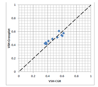
With comparing Vsh. estimated from cross-plot method and Vsh calculated from gamma ray (with using of CGR) is seen that these values are very close together for each point Figure 10, therefore, cross-plot method can be used to determine shale volume and effective porosity with acceptable accuracy.

Figure 10: Vsh estimated from cross-plot and Vsh. calculated from -gamma ray spectrum (CGR) for depth interval 2718.5-2719.5m (Accuracy: 94 - 99%).
Depth intervals “2730.5-2731.5m”
This section of formation has intermediate volume of shale and saturated with formation water Figure 11. After plotting measured points of this interval on cross-plot Figure 12 is seen that aggregation of points is around dispersed shale line. So, distribution mode of shale for this section of formation is dispersed. Vsh and φe estimated from cross-plot for each point of this interval and are given in Table 4.
Depth |
NPHI |
PHID |
PHIE-CP |
VSH-CP |
VSH-CGR |
2730.5 |
0.142 |
0.045 |
0.022 |
0.286 |
0.207 |
2730.6 |
0.151 |
0.049 |
0.024 |
0.302 |
0.239 |
2730.7 |
0.158 |
0.052 |
0.027 |
0.312 |
0.270 |
2730.8 |
0.162 |
0.054 |
0.028 |
0.319 |
0.289 |
2730.9 |
0.163 |
0.055 |
0.029 |
0.318 |
0.289 |
2731.0 |
0.159 |
0.054 |
0.029 |
0.310 |
0.272 |
2731.1 |
0.154 |
0.051 |
0.027 |
0.301 |
0.247 |
2731.2 |
0.145 |
0.047 |
0.024 |
0.288 |
0.224 |
2731.3 |
0.132 |
0.041 |
0.019 |
0.270 |
0.205 |
2731.4 |
0.117 |
0.034 |
0.014 |
0.243 |
0.190 |
2731.5 |
0.100 |
0.027 |
0.011 |
0.214 |
0.171 |
Table 4: Vsh and PHIE (φe) estimated from cross-plot (CP) for 2730.5-2731.5m depth interval.
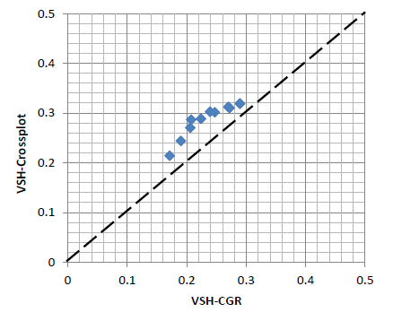
With comparing Vsh estimated from cross-plot and Vsh calculated from gamma ray (with using of CGR) is seen that these values are very close together for each point Figure 13, therefore, cross-plot method can be used to determine shale volume and effective porosity with acceptable accuracy.12

Figure 13: Vsh estimated from cross-plot and Vsh calculated from gamma ray spectrum (CGR) for 2730.5-2731.5m depth interval (Accuracy: 89.7-97%).
Depth intervals “2743-2744m”
This interval of formation has low volume of shale and saturated with formation water Figure 14. After plotting measured points of this interval on cross-plot Figure 15 we seen that aggregation of points is around dispersed shale line. So, distribution mode of shale for this section of formation is dispersed. Vsh and φe estimated from cross-plot for each point of this interval and are given in Table 5.
Depth |
NPHI-COR |
PHID-COR |
PHIE-CP |
VSH-CP |
VSH-CGR |
2743.0 |
0.087 |
0.043 |
0.033 |
0.128 |
0.136 |
2743.1 |
0.100 |
0.048 |
0.036 |
0.152 |
0.155 |
2743.2 |
0.112 |
0.052 |
0.038 |
0.174 |
0.171 |
2743.3 |
0.119 |
0.055 |
0.040 |
0.189 |
0.181 |
2743.4 |
0.121 |
0.056 |
0.041 |
0.193 |
0.184 |
2743.5 |
0.118 |
0.055 |
0.040 |
0.186 |
0.178 |
2743.6 |
0.110 |
0.052 |
0.038 |
0.171 |
0.165 |
2743.7 |
0.099 |
0.047 |
0.035 |
0.152 |
0.146 |
2743.8 |
0.088 |
0.041 |
0.031 |
0.136 |
0.125 |
2743.9 |
0.077 |
0.036 |
0.026 |
0.121 |
0.106 |
2744.0 |
0.068 |
0.032 |
0.024 |
0.105 |
0.090 |
Table 5: Vsh and PHIE (φe) estimated from cross-plot (CP) for depth interval 2743-2744m.
With comparing Vsh estimated from cross-plot and Vsh calculated from gamma ray (with using of CGR) is seen that these values are very close together for each point Figure 16, therefore, cross-plot method can be used to determine shale volume and effective porosity with acceptable accuracy.
This investigation is done for many depth intervals of Tabnak Well C in Kangan Formation, central Iranian oil field. By using distribution of shale types for each interval, shale volume and the effective porosity for each point have been estimated by cross-plotting method. A triangle neutron-density porosity cross-plot has been applied for this purpose.
Vsh estimated from cross-plot has been validated with Vsh calculated by Gamma ray spectrum using equations (1) and (3) in unsaturated shale and equation (4) in gas saturated shale. Also, φe estimated using cross-plotting method has been compared with φe, measured by well logs. In shaley formations saturated with hydrocarbon, equations (4) to (17) have been used for correction of shale volume and effective porosity. It is seen that, these shale volumes are very close together. Therefore, cross-plotting method can be used to determine shale volume and effective porosity with acceptable accuracy.
Cross-plotting is a quick and commodious method in comparison with other methods, such as core analysis or well logs for determining petrophysical parameters.
This method can be used for any formation which has shaley layers using cross-plotting of φNSh versus φDSh in each depth interval. Shale types should be determined and recalibrated after a few well has been drilled. The results of this method can be used to estimate productivity and capacity of a reservoir.
None.
The author declares no conflict of interest.

©2017 Ghassem, et al. This is an open access article distributed under the terms of the, which permits unrestricted use, distribution, and build upon your work non-commercially.