International Journal of
eISSN: 2475-5559


Review Article Volume 3 Issue 1
1Electric Power Research Institute, USA
1Electric Power Research Institute, USA
Correspondence: JD Parker, Electric Power Research Institute, USA
Received: December 08, 2017 | Published: January 10, 2018
Citation: Parker JD, Siefert JA. Creep fracture in tempered martensitic steels. Int J Petrochem Sci Eng. 2018;3(1):1-7. DOI: 10.15406/ipcse.2018.03.00068
As long term laboratory creep data became available the original estimates of the allowable design stresses for creep strength enhanced ferritic steels (CSEF) were reduced. Thus, even in properly processed steel, the long term performance and creep rupture strength reported is below that originally predicted from a simple extrapolation of short term data. In addition, the typical alloy compositions for these steels specified by Codes provide reasonable strength but can steels can exhibit brittle creep behavior. This inherent brittle behavior results in notch weakening and the need to invoke weld strength reduction factors. Moreover, creep brittle behavior, and the associated micro void development, promotes burst rather than leak type fracture in components. The existence of significant densities of voids further complicates in-service assessment of condition and weld repair of these steels. It is now clear that the levels of ductility required in engineering applications necessitate proper control of composition (including trace elements), steel making and processing and all heat treatments. This paper examines background on the development of creep voids in martensitic steels and discusses metallurgical and stress state factors which promote brittle behavior.
Creep strength enhanced ferritic (CSEF) steels which contain 9 to 12%Cr have become the steels of choice in many industrial high energy systems. The typical compositions of alloy types P91, P92 and E911 are compared with 12CrMoV in Table 1. These steels are selected for use in applications where high temperature creep can occur because of a favorable balance between cost and properties.1,2 The excellent creep and fracture resistance are achieved because the microstructure, which, when properly processed, exhibits a tempered martensitic matrix containing a substructure with a high dislocation density and a fine dispersion of second phase precipitates. It has been pointed out that the typical alloy compositions for these steels frequently do not include recommendations for upper limits on trace or ‘other’ elements. At least for Grade 91 steels this situation is changing.3 Because it is well established that inclusions and trace elements can lead to embrittlement it is likely that further controls will be needed to reduce the risk of in-service fracture in other CSEF steels.
Mass % |
12CrMoV |
P91 |
P92 |
E911 |
C |
0.2 |
0.09 |
0.11 |
0.12 |
Si |
0.26 |
0.29 |
0.04 |
0.13 |
Mn |
0.51 |
0.35 |
0.46 |
0.56 |
Cr |
11 |
8.7 |
8.96 |
8.7 |
Mo |
0.9 |
0.9 |
0.47 |
0.97 |
W |
- |
- |
1.84 |
0.96 |
Ni |
0.44 |
0.28 |
0.06 |
0.29 |
V |
0.29 |
0.22 |
0.2 |
0.2 |
Nb |
- |
0.072 |
0.069 |
0.62 |
N |
- |
0.044 |
0.051 |
0.066 |
B |
- |
- |
0.001 |
0.0004 |
Austenitisation |
1050°C |
1050°C |
1065°C |
1060°C |
Tempering |
750°C |
765°C |
770°C |
770°C |
Table 1 Typical compositions and heat treatments used for martensitic steels
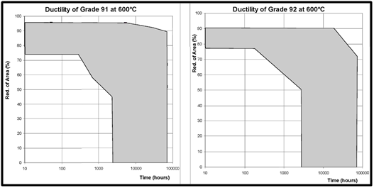
The complex nature of the long term creep behavior of 9 to 12% Cr steels4,5 is emphasized by consideration of data compilations of creep ductility. Published information showing the variation of the reduction of area at fracture after creep testing at 600°C is shown in Figure 1 for Grade 91, Grade E911 and Grade 92 steels. In short term tests, the samples fail with high ductility due to local deformation and ‘necking’ of the samples. In long duration tests some high ductility type failures are reported. However, it is apparent that as lives increase there is a tendency for some tests to fail in brittle manner. This means that for all three steels there is a very large variation in fracture behavior even in tests at a single temperature, namely 600°C. This is clearly significant since 600°C is a typical in-service temperature for these steels. Indeed, in the development of steel P92 a target was set for the minimum reduction of area to be at least 40% at 10,000 hours and 600°C. It is apparent that results include data where this aim for ductility is not being achieved. Greater understanding of the reasons for the wide variation in fracture characteristics of these martensitic steels is clearly important for in-service Fitness for Service and Risk Assessments.
The complexities associated with establishing the factors affecting the creep behavior of CSEF steels mean that it is challenging to identify and quantify the influence of individual parameters. As emphasized,6 most published research suffers from a number of serious drawbacks, for example:
The present paper reviews information on long term creep fracture behavior in 9 to 12%Cr martensitic steels and discusses approaches for minimizing the susceptibility for nucleation of voids so that creep brittle fracture can be avoided.
There has been apparently conflicting evidence reported regarding when creep voids form during creep of martensitic steels. Indeed, several studies have reported that voids can only be identified late in creep life.7 In contrast, other work has demonstrated that creep voids nucleate relatively early in the creep life.8,9 These apparently conflicting observations are considered with respect to the creep behavior of selected CSEF steels.
Damage in 12%Cr (X20) steel
The martensitic steel 12% Cr-Mo-V steel has been used in boiler applications for around 50 years. Interestingly, even in this one steel there are conflicting observations regarding the formation of creep voids. Thus, reviews of performance have been published showing that remarkable few components have been found with creep voids detectable by optical microscopy.10 In contrast, some experience has shown that creep cracking in components has occurred and replacement of components has been required. While these observations have all been made for steels operating beyond 100,000 hours, it could be that the variation in observations is linked to the temperature of operation. It is well known that the accumulation of creep damage is very dependent on the exposure temperature. However, the information considered here shows that variable fracture behavior has been identified even in samples exposed at the same creep temperature.
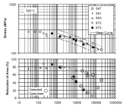
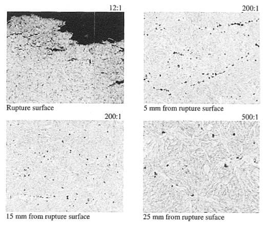
The creep strength and ductility for a number of different X20 steels tested at 550°C is compared in Figure 2.11 Figure 2 shows data up to and even beyond 100,000 hours duration. While there is no major difference in creep strength for the different casts, there are significant differences in the reduction in area measured after testing. At the high stress levels, all of the specimens rupture in a ductile manner. These failures are linked to voids which form and grow plastically at large inclusions. The inclusions are hard particles within the plastically deforming matrix and at some critical value of strain void formation occurs. In general, it has been reported that relatively large oxide and sulfide inclusions are more effective in the initiation of voids which grow by plastic deformation than small particles. The generally smaller, second phase particles do not appear to play a role in the ductile high temperature rupture of 12% Cr-Mo-V steel. It is apparent that some casts show significant decreases in ductility for test lives of around 10, 000 hours. Thus, at low stresses, creep cavitation appears to be the dominant damage mechanism. The change in the controlling mechanism results in much lower strains to rupture, Figure 2. Indeed, as shown in Figure 3, posttest metallographic examination of samples which failed with low reduction of area (R of A) revealed significant number densities of individual voids. Indeed, not only were creep voids and micro cracks found at the failure location but damage was also observed along the gauge length even well away from the fracture surface. These observations demonstrate that, under the testing conditions employed, void nucleation had taken place generally throughout the whole gauge length. As expected, link up of damage focused at a specific location but even here the deformation observed is mostly associated with developing the strain needed to grow cracks across the gauge section Figure 3.
Damage development in specific tests on tempered martensite ferritic steel (German grade: X20) at a stress of 120MPa and a temperature of 550°C has been reported.6,12 These test conditions resulted in a creep life of 139,971 hours. Tests were also performed under the same loading conditions but with interruptions after 12,456, 51,072 and 81,984 hours. That is test specimens were examined at life fractions of about 9%, 37% and 59%. It was reported that nucleation of cavities was found in each of the samples examined. Thus, it appeared that void nucleation occurs continuously during creep exposure. Detailed study showed that it appeared that the number of creep voids present, i.e. the cavity density, was proportional to the creep strain.13
As illustrated in Figure 3, a characteristic feature of creep cavitation in high chromium ferritic steels, is that cavities are not only found on prior austenite grain boundaries (PAGBs) but also in the interior of former austenite grains. There are additional internal surfaces such as at inclusions, at sub- grain boundaries and at high angle ferrite boundaries. These locations can act as ‘trap’ sites for trace elements and thus have the potential in increase the susceptibility to creep cavity formation and accelerated cavity growth.
Damage in grade 91 steel
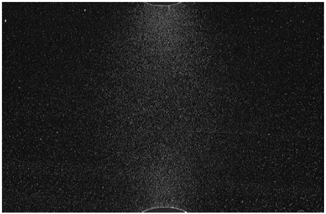
There has been a very wide range in the reported reduction in area measured for creep tests performed on Grade 91 base metal. This wide range is illustrated with reference to Figure 1. As shown, the measured R of A begins to fall even for test lives of the order of 5,000 hours at 600°C. In contrast, some tests of close to 100, 000 hours are shown with a reported R of A above 70%. While this range of behavior may be in part explained by differences in test temperatures and specimen dimensions, further evaluation of specific test results is of value to review potential trends in behavior. It is apparent that under condition of low R of A, fracture again occurs predominantly as a result of the nucleation and growth of creep voids. A micrograph with very high number densities of individual cavities in the base metal of a Grade 91 steel notched creep test is shown in Figure 4. The formation of very high number densities of individual cavities before the formation of macro cracking is a direct result of the steel investigated exhibited a high susceptibility to void nucleation.
Previous work has shown that there is a link between N:Al ratio and creep strength in tempered martensitic Grade 91 base metal.14 The observed behavior has been explained on the basis that in Grade 91 steel the levels of nitrogen are set so that strengthening will involve the formation of MX type carbides, nitrides and carbonitrides. When excess aluminium is present in the steel, this combines with nitrogen to form aluminium nitrides.14 These aluminum nitrides are relatively large and so do not contribute to creep strength. Thus, since the level of free nitrogen is reduced by the formation of aluminium nitrides, the volume fraction of MX precipitates is decreased and the creep strength is decreased. Previous work has shown that there can be a link to the formation of aluminium nitrides and increased susceptibility for the nucleation of creep voids. This observation is consistent with the behavior reported for other boiler steels where steels with higher inclusion levels exhibited lower creep ductilities than ‘clean’ steels of the same composition.15
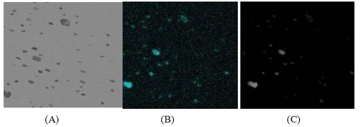
Examination of Grade 91 steel after creep testing has been performed to measure the number density of creep voids and to evaluate factors involved in void nucleation. It is apparent that the creep behavior of tempered martensitic steels is influenced by nonmetallic inclusions. In cases where these inclusions exceed a critical size there is established evidence that voids are nucleated on the ‘hard’ particles. Photomicrographs in Figure 5 illustrate this behavior. A back scattered electron micrograph of the creep voids present is shown in Figure 5a, with Figures 5b & c showing elemental maps for oxygen and silicon. It is apparent at least some of the creep voids are associated with particles which have relatively high concentrations of silicon and oxygen.
When considering nucleation of creep cavities the local microstructure and composition are clearly of particular interest. Elements which have been shown to decrease the resistance to creep fracture in engineering steels include phosphorus (P), sulfur (S), Copper (Cu), Tin (Sn), Antimony (Sb), Arsenic (As). A systematic study evaluating the influence of these elements on the strength and fracture behavior has been published.16,17 The reduction in the rupture life resulting from the higher amount of tramp elements at 650°C does not appear to be caused by the increase in the creep rate, but rather by the decline in creep ductility. This is consistent with the Sb and Sn-doped samples exhibiting minimal R of A. Consequently, the rupture life associated with the Sb- and Sn-doped samples is shorter than that of the P- and S-doped samples, Figure 5. The rupture life associated with the Cu-doped sample was seen to be independent of the content of Cu. This is because the Cu- doped samples exhibited poor ductility irrespective of Cu content, Figure 5B. Poor ductility linked to elevated copper levels has also been found in other work.18
The results from Grade 91 steel provide insight into why the observed distribution of cavities in tempered martensitic base metal is very variable for different casts. It is apparent that the size and distribution of non-metallic inclusions and the concentration of trace elements both significantly influence the nucleation of creep voids. Since these factors will not simply influence the behavior at grain boundaries, voids nucleate in different positions. In the steels with lowest creep ductility, void nucleation starts early in life and continues with increasing strain Figure 6.
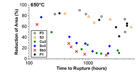
Some of the trace elements are not controlled in applicable component specifications even though as shown elements such as Tin (Sn), Antimony (Sb) and Copper (Cu) can significantly reduce the creep ductility of 9%Cr steels.16,17
Damage in grade 92 steel
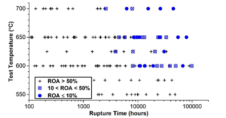
It is apparent from consideration of Figure 1, that variability has also been noted in the fracture mode of Grade 92 base steels. An alternative approach to visualization of creep fracture behavior to the typical variation of R of A with rupture life is shown in Figure 7. Here, the rupture life reported for different test temperatures is shown, with selected ranges in R of A designated by different symbols. The general key to this Figure is that samples with an R of A greater than 50% are shown as a cross, with tests with an R of A below 10% are shown as a solid circle.
The tests included in Figure 7 cover data from many different sources, yet a general trend in the rupture behavior is apparent. Thus, for tests at 650°C and durations near to, or above 10,000 hours the recorded ductility is below 50%. In contrast, for tests at 550°C even with durations approaching 100,000 hours the reported ductilities are above 50%. Interestingly, the results reported for tests at 600°C, i.e. near to the design temperature for many Grade 92 steel components, tests with durations above 10,000 hours show a mixed behavior. Thus, some steel casts show relatively low ductility at lives around 10,000 hours yet others show R of A above 50% even at creep rupture lives very close to 100,000 hours.
Clearly, the fact that very low creep ductilities have been reported in Grade 92 base metal samples using test conditions near typical operation of advanced boilers requires further study. The fact that differences in fracture characteristics have been found for tests in different temperature regimes and for different compositions, suggests that both fabrication and creep testing factors are important in establishing details of damage. In view of the metallurgical complexities of advanced tempered martensitic steels, careful planning, selection of samples for examination followed by the application of advanced microscopy are required to establish trends in behavior. Details from these characterization activities have been presented.19 However, selected information is provided here to compliment the present review of fracture behavior in 9 to 12% Cr steels.
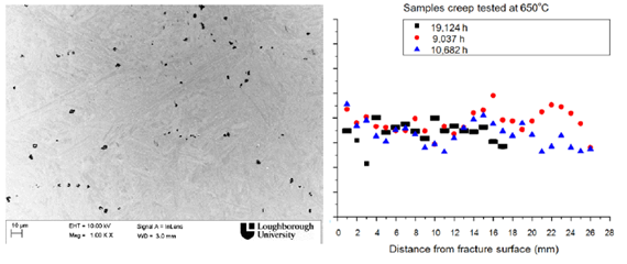
A typical micrograph showing the development of cavities after creep testing of Grade 92 base metal is shown in Figure 9A. Samples were selected for examination after testing at 550°C, 600°C and 650°C. As indicated in Figure 8, all the tests at 650°C with duration of above about 10,000 hours showed an R of A below 50%. Detailed characterization of samples tested to failure at 9,037, 10,682 and 19,124 hours at 650°C showed that a uniformly high number of creep voids were present along the gauge length, Figure 9A, Figure 9B. This evidence on Grade 92 steel supports the earlier results showing a high degree of uniformity in void density for long term tests on X20 steel, Figure 3. For the Grade 92 tests, the size of cavities at fracture was generally in the range from 2.1 to 3 µm.19 However, detailed sizing was difficult because the voids were not spherical.
Because of the complex shapes of the creep cavities even careful metallographic preparation and evaluation has difficulties to unambiguously characterize voids and their relationship to micro structural details. A sophisticated approach involving serial ion beam sectioning followed by documentation was therefore applied.20 This approach allowed both the void shape and the associated particles to be reconstructed in three dimensions. An example of a reconstruction is shown in Figure 9. In the reconstruction shown, the cavity has a diameter of around 2 µm. This void was clearly associated with a boron nitride particle of around 1-1.5 µm. Much smaller second phase particles including Laves phase were found to decorate the inside of many of the cavities. In some cases, fine manganese sulphide (MnS) or alumina (Al2O3 ) particles were found within the cavities. It is potentially the case that the fine MnS or Al2O3 formed in the steel at very high temperatures act as sites which promote the nucleation of boron nitride during subsequent cooling.
For typically processed tempered martensitic steel base metal, it has been observed that the long term performance and creep rupture strength is below that originally expected from simple extrapolation of short term creep data. This effect has resulted in reductions in some of the values quoted as representing long term creep life. The reasons for the loss of long term creep rupture strength have been investigated extensively4,-6 for a number of 9 to 12 Cr steels. The following microstructure degradation effects appear to be primarily responsible for the loss of creep strength:
The precipitation of Z phase, M6X carbonitrides and Laves phase during creep can cause a loss of creep strength at long times. The loss of strength occurs if the formation of these phases is sufficient to result in a significant reduction in the fine M2X and MX and or M23C6 precipitates. The size (which determines the climb distance required to overcome the particle and the number density (which determines the mean particle spacing and thus the particle back stress are critical to stabilizing the dislocation substructure and hence, play a major role in determination of the creep strength. It has been the primary focus of the present paper to consider the factors affecting the nucleation and growth of creep voids. This focus was established in part because high densities of small voids can have a particularly significant influence on approaches to manage the safe life of boiler components and in part because while the creep dependent micro structural changes have been widely studied, there is less work reported on creep void development. This is particularly true for the tempered martensitic microstructures present in base metal.
It is now clearly established that for creep conditions at or close to those of components in power boilers, creep voids can be nucleated early in life.8,9 There have been different opinions published regarding void nucleation. In particular, several papers have suggested that creep voids are only formed late in life. This diversity of findings is due to a number of factors, including the following:
In long term creep tests on CSEF steels, the voids grow throughout the creep life and will be around 1 to 2μm in size at, or very close to, fracture. This size of void is important because it is only relatively close to fracture that individual voids can be relatively easily identified using optical microscopy at the magnifications around 400 time’s magnification. Due to the non-symmetrical shape of the creep voids, sample preparation is critical to identification of voids. It appears that long term creep exposure of X20 steel can results in the development of higher densities of voids than in other tempered martensitic steels. In X20 steel it is generally agreed that the number density of voids increases with creep strain, with the number of voids at or very close to fracture in the range 2000 to 10,000 mm-2.11,13
The relationship between boron and nitrogen concentration associated with the formation of BN inclusions in high Cr ferritic heat resistant steels is shown in Figure 10. Chemical analyses of twenty-three steels, including P122 and P92, with different concentrations of boron and nitrogen were reported.21 In each steel, SEM examination was performed to establish, or otherwise, the existence of BN inclusions. Except for the commercial P92 and P122 steels, manufacture of each cast involved melting of 50 to 150 kg of steel, hot working at 1200 to 1000°C, normalizing at 1100°C and holding 0.5 to 1h, tempering at 770 to 800°C and holding 1 to 4h. In Figure 10, solid circles represent casts where coarse size BN inclusions, i.e. over the size of 1μm, were observed. The triangular symbols show small BN inclusions, i.e. under 0.5μm, and open circles represent no BN. In this experimental concentration range, BN type inclusions could not be found by SEM observation in the concentration range less than 0.001%B or 0.015%N.
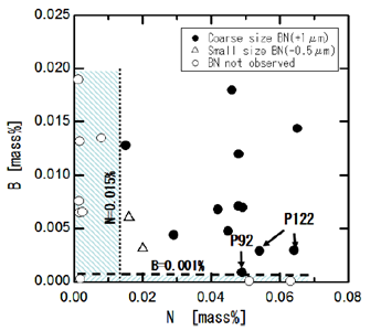
The fact that in the majority of steels with boron and nitrogen large sized BN inclusions are present, means that in each case about 80% of added boron forms BN inclusions. After normalizing at 1100°C and tempering at 800°C only 20% of added boron remains dissolved in the metal matrix. It is the available (i.e. not in BN inclusions) boron which is thought to have the beneficial effects on creep strength. These benefits are achieved through improvements in the stability of precipitates and positive influences at grain boundarie.
Observations of creep voids for assessment of condition of in-service components have been used for many years Figure 11. The most widely used approaches for this form of evaluation is through the application of metallurgical replicas. In most cases, the use of replicas was carried out on low alloy steels, often by examination of welds and the associated heat affected zone (HAZ).
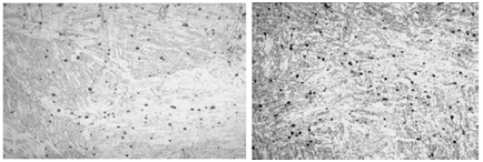
In CSEF steels, service experience suggests that in many cases creep damage has been detected in the HAZ. It is apparent that in many cases, the greatest extent of creep damage in the HAZ occurs below the surface of the component. Thus, the benefit from carrying out inspections using replication on the outside surface of the component is limited. However, 12%Cr (X20) steel replica assessments have been used in boiler and piping applications for a long time. The following observations are based on a summary from numerous inspections, including the use of metallographic replicas.22,23 Metallographic assessment of voids typically involves using an optical microscope at about 400 times magnification. Detailed quantification of the number density of voids (expressed as the number of voids per square millimeter) may also be performed at higher magnification. However, it should be recognized that the density of voids identified will increase with the magnification used. Numerous small sub-microscopic creep voids with diameters less than 0.1µm can be detected very early in life, <10 percent of the creep life. These voids grow and become visible under an optical microscope at a magnification of 400 x when they have achieved a size of about 1µm. At high creep life fractions, i.e. close to crack initiation, the number of voids visible at 400 times does not change significantly but the size increases. The guidance from evaluation of X20 components is that further engineering assessment of bends should be performed if the void density exceeds 500 voids mm-2 or if more than 50 percent of the voids observed exceed a size of 2.5μm.22,23
Typical creep damage development with time is illustrated in Figure 12. These micrographs show actual field measurements from a 12CrMoV steel steam pipe bend which operated at 532°C. This bend had been incorrectly heat treated during fabrication and hence exhibited low creep ductility. After operation for approximately 160,000 hours inspection showed that high numbers of creep voids were present. The average void density at that time was estimated as 1025mm-2. Using typical values for the number density of voids at crack initiation, this void density indicates that cracking was imminent. However, no replacement component was available. Instrumentation was used to directly monitor the component and operating conditions were reduced to minimize the rate of creep damage development. A final inspection was performed after an additional operating period of 12,550 hours.
Because of the need to monitor the damage in this bend it was possible to track void size with time. As shown in Figure 12, the percentage of voids greater than 2.5μm increased respectively to 23%, 34% and 43%. Over this same period, the fraction of voids greater than 3.5μm increased from 3% to 20%. It is thus clear that significant void growth had taken place.
It is apparent that designers, manufacturers and operators of high energy equipment seek to use the most cost effective alloys which will provide the required level of performance. Increasingly, this performance should be achieved without the use of extreme conservatism. Thus, it is important that the preferred alloys do not exhibit excessively large variations in properties. In fact, research to date has shown that for metallurgically complex alloys such as Grade 91 and Grade 92 steel, changes in composition and/or heat treatment have a significant influence on high temperature behavior. Indeed, it is increasingly being questioned whether fitting data using a relationship to describe ‘average’ performance has value. It appears that average is simply a statistical determination but cannot provide support to engineering decision making. Instead, engineering decisions linked to Fitness for Service should take into account a Metallurgical Risk factor.
This Metallurgical factor is required since tempered martensitic steels such as X20, Grades 91, 92, E911 and 122 all exhibit a trend to relatively low ductility with increasing constraint. The tendency for brittle behavior is in all cases due to the formation of creep voids. The detail of the number of voids formed, and the tendency for reductions in strain to fracture, is different for the different steels. However, it appears that in all cases, void nucleation is related to the presence of trace elements and hard non-metallic inclusions. A key factor in determining whether the inclusions nucleate voids is the particle size. Thus, only inclusions of a sufficient size will act directly as nucleation sites. However, even fine inclusions formed during steel making (such as Al2O3) may also play a role in promoting void formation. Analysis of the creep cavities formed in P92 steel revealed that the voids were associated with hard particles. The vast majority of these particles were BN which appeared to have developed on the alumina or magnesia particles which are formed during de-oxidation or originate from the refractory of the steel making furnace. Once formed, post fabrication heat treatment above about 1200°C appears to be sufficient to dissolve the BN. Control of composition and modified heat treatment practices during fabrication offer the potential to reduce the susceptibility for brittle creep fracture behavior in CSEF steels. Alloys with high creep ductility significantly reduce the risk of catastrophic fracture of components.
None.
The author declares no conflict of interest.

©2018 Parker, et al. This is an open access article distributed under the terms of the, which permits unrestricted use, distribution, and build upon your work non-commercially.