International Journal of
eISSN: 2475-5559


Research Article Volume 1 Issue 2
1McCoy School of Engineering, Midwestern State University, USA
1McCoy School of Engineering, Midwestern State University, USA
Correspondence:
Received: August 08, 2016 | Published: September 19, 2016
Citation: Elsharafi M, Chancellor C, Kirby C, et al. Hydrochloride acid effect on the PH value of the superabsorbent polymer (SAP) solutions. Int J Petrochem Sci Eng. 2016;1(2):21-26. DOI: 10.15406/ipcse.2016.01.00006
In mature oil fields, the use of water injection is common, but is limited by reservoir heterogeneity. Differences in permeability can increase water production and subsequently increase operating cost. Superabsorbent polymers can be used to control reservoir fluid flow. Understanding the kinetics of these polymers, such as AT-O3S and 2G-110, is the key to their proper use during the treatments. The polymers used are both a cross linked Sodium polyacrylic acid, these three factors determine the extent to which the polymers will absorb water, which induces swelling. Swelling is strongly dependent on salinity, pH, and temperature. This study investigated the influence of pH by using brines with different percent weight ratios of deionized water and Calcium Chloride. The polymer is destroyed and a white precipitate made of Calcium polyacrylate is formed, due to the presence of divalent cations in the solution. In order to decrease the effects of the reaction, the pH of the solution was modified. As pH drops, it is observed that the precipitation decreases substantially, especially in dilute solutions. It can be inferred that the precipitation effects can be mitigated through the appropriate use of acid washes, preflushes, and polymer concentration in many cases. However, high temperatures might cause further precipitation in brines containing divalent cations.
In the past four decades, there has been a significant drive to increase extraction efficiency in oil reservoirs. Previously uneconomical reservoirs can become viable and productive assets to petroleum companies. For the permeable reservoirs, water injection is very effective and is commonly used to artificially pressurize the formation. This allows for continued production even with a low pressure gradient. However, it is a proven fact that water injection operation efficiency is limited by reservoir heterogeneity.
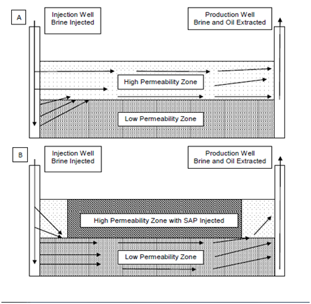
The variation of permeability and pore geometry in a reservoir can significantly affect the recovery efficiency of water injection operations.1,2 As the water or brine is injected into the formation, the fluid will flow through the path of least resistance. Essentially, the fluid flows through the more permeable zones and sweeps the oil from these areas of the formation, leaving behind the oil in the tighter, low permeability zones.3,4 An example can be seen in Figure 1A. After some time, oil production decreases as the high permeability zones are swept, although low permeability zones remain relatively untouched.5 The high permeability zones can be swept of around 60% of their oil while areas of low permeability only lose around a quarter of their oil during an untreated water injection operation according to the work done by Cui et al in 2011. This variation in permeability causes a substantial increase in water production.3 In fact, excess water production can reach up to 98% of a well’s output.6 Greater water production can cause environmental and economic issues as the water tends to have a high salinity, especially after the solution travels through the reservoir. These high salinity brines must be processed, transported, and disposed of in a safe manner, all of which can be costly.7 In fact, the worldwide cost of excess water production was estimated at $40 Billion dollars annually in 2000.8 Since then, this statistic has undoubtedly grown substantially alongside the oil industry.

Figure 1 Heterogeneous Reservoir Flow during Water injection a) Before SAP Treatment and b) After SAP Treatment.
In order to decrease excess water production and increase oil output in a permeable reservoir, the reservoir’s heterogeneity must decrease.5 The best way to change the heterogeneity is to impede the access of the injected water to the high permeable zone. This can be done mechanically through the use of concrete or sand, or it can be done chemically through the use of gels and polymers. The focus of this work was on the use of a cross linked Sodium polyacrylate, polyacrylic acid, a super absorbent polymer (SAP), which absorbs water and swells. In heterogeneous and permeable reservoirs, SAPs can be inserted into the reservoir to decrease the permeability of the high permeability zone. Application of an SAP will drop the permeability of both the high and low zones. However, the treatment affects the high permeability zone much more than the low permeability zone when applied correctly.9–11 During injection, the pressure required to push an SAP particle through a passage goes up as passage diameter decreases.12 This allows for deeper SAP penetration in the high permeability zones and more effective blocking of these zones.
Understanding the fluidic kinetics of an SAP and planning a treatment based on reservoir conditions is crucial to its employment, as the kinetics determines the polymer’s in-formation permeability.13–15 Damage (or reduction in permeability) to the low permeability zone can cause serious issues, but an analytical method to prevent damage has been introduced.16,17 Proper SAP treatment decreases the heterogeneity of the formation, resulting in a relatively even flow distribution. An example of a treated reservoir can be seen in Figure 1B. The unswept low permeability zones can now be swept more effectively, allowing for increased production, a longer well life, and higher reservoir recovery efficiency.
The above mentioned SAP swells to a specific amount when exposed to water, known as the swelling ratio. This swelling ratio strongly depends on the solution salinity, pH, and temperature.18 In a reservoir, the three most prevalent cations present are Sodium+, Calcium+2, and Magnesium+2 in descending order.5 The reaction between Sodium+ ions and SAPs is well documented, and the results show a drop in the swelling ratio as a brine’s Sodium concentration increases.13,9–11,18,19,21 The effects of divalent cations such as Calcium and Magnesium have not received the same attention, however. The presence of divalent cations in a brine, Calcium in the case of this work, is destructive to the swollen polymer. The Calcium present in a brine solution reacts with the Sodium salt cross linker present in the polymer chain. At normal to high pH values, the carboxyl group of the Sodium salt becomes ionized. When divalent cations are present, this ionization results in the replacement of Sodium with Calcium in the polymer chain. The result is Calcium polyacrylate, which precipitates out of the solution. This reaction destroys the polymer. Even dilute Calcium brines cause significant deswelling and precipitation, especially when introduced after the polymer has fully swollen. There is evidence that pH has a significant inhibiting effect on the precipitation reaction by suppressing the ionization of the carboxyl group. The resulting polymer kinetics are the focus of this work. The pH range of Calcium Chloride brines tends to be from about 8 pH to 10 pH, while it has been stated that a pH range of approximately 3 pH to 4 pH will prevent polymer destruction.22 Complicating matters, pH has a direct effect on the swelling of the SAP, increasing the swelling ratio as brine pH increases until reaching about 6 pH.10–11 Temperature can also affect the reaction. As temperature increases, the SAP becomes less stable in Calcium brines and precipitates out further. In the absence of divalent cations, an increase in temperature results in an increase in swelling ratio.18,10,11
In the field, mitigating the effects of divalent cations can be done through the use of preflushes, which can significantly dilute or remove undesirable salts. In many instances, reservoirs that have undergone prolonged water flooding or water injection treatments can be assumed to be preflushed. Such treatments are not always successful, however.23 Remnants of divalent cations may remain and prevention of the reaction between them and the polymer could increase the success rate of SAP treatments.24
Equipment
In order to measure out the desired quantities for the brines and polymers, a Tree® HRB103 electronic precision balance was used. For agitation and mixing brines, a small VWR® Lab Dancer S41 test tube shaker was employed on either the 15mL or the 50mL graduated centrifuge tubes with screw on caps containing the material. The effect of temperature on the swollen polymer was investigated through the use of a Julabo® F25 MC bath circulator using water as the bath fluid. The temperature of the fluid and the samples was confirmed in Celsius using a glass thermometer. Disposable pipettes were used to introduce acid to the brine solutions and the pHs of the solutions were measured with an Oakton® pH 150 series pH meter.
Materials
Brines were mixed using deionized (DI) water and Calcium Chloride. The concentration was measured by percent weight and was mixed in a clean centrifuge tube. If needed, the contents would be mixed using the test tube shaker for a short period of time. The Calcium Chloride concentration was either 1% (% wt.) or 0.5% (% wt.), with the latter being the main focus. Hydrochloric acid (HCl) at differing concentrations was used to control pH. The concentrations used were 0.1N and 6N. Two polymers were used, AT-O3S and 2G-110, which differ only in particle size. Both SAPs were manufactured using inverse suspension polymerization, which results in uniform, spherical particles. The particle sizes ranged from 35-60 mesh (250 to 500 microns) for AT-O3S and 60-120 mesh (125-250 microns) for 2G-110. This particular polymer is sensitive to salinity, pH, and temperature. Both polymers were purchased from Emerging Technologies®.
Brine preparation
In order to prepare the brines, the desired amount of DI water was weighed out on the electronic balance scale and added to a clean, dry centrifuge tube. Calcium Chloride was then weighed out and added to the water, creating a brine. The desired brine concentration determined the amounts of each component. Calcium Chloride concentrations varied from 1% (by wt.) to 0.5% (by wt.). The brine was agitated after addition of the salt to increase the dissolution speed. The pH of the brine solutions, which varied from 8 pH to 10 pH, was modified by using a disposable pipette to add hydrochloric acid, measured by drops, to the brine solution. The pH and temperature of the solution was then measured and recorded. The pH range achieved was mostly in the range of 0.5 pH to 4 pH.
Polymer preparation
The polymer was weighed out by percent weight of the brine solution. Do note that the polymer was not included in the brine solution weight. For example, 1% polymer for 15 grams of brine would be 0.150 grams of polymer, and the test weight of the experiment would be 15.15 grams. After the correct amount of material had been weighed out, it was added to a separate, dry centrifuge tube.
Test execution
After preparing the brine and polymer in 50mL centrifuge tubes, the next step was to add the brine to the polymer. The brine was poured on top of the polymer at time 0 and was immediately agitated on the test tube shaker. This lasted for 40 seconds, after which the polymer was allowed to settle for 20 seconds and a volume reading was taken. The process was repeated, resulting in 1 minute time intervals. Readings were taken until changes in volume failed to occur for 4 to 5 minutes, at which point the solution was considered stable. The volume data was converted to swelling ratio by finding the change in volume from time 0 and dividing by the volume at time 0 as seen below in equation 1. Since the polymer was originally measured out by weight, density had to be used to find the original volume.
Equation 1.
In Equation 1, S is the swelling ratio, v is the recorded volume, and Vo is the preswelling volume
Equation 2.
In Equation 2, Vo is the preswelling volume, mp is the polymer’s measured mass, and ρp is the polymer’s density. The density used was 1.23 g/mL.
Temperature effect
Temperature test samples, composed of polymer and brine, were collected from previously performed experiments and transferred to 15mL centrifuge tubes so they would fit in the circulator. The bath temperature was adjusted on the circulator, and after some time had passed, the temperatures of the samples were taken. If the samples were at the desired temperature, volume readings would be recorded for each sample. The temperatures tested were 24˚C (room temperature), 40˚C, 60˚C, 80˚C, and 90˚C. The volume data was converted into swelling ratio by using the same density as above and the known room temperature final swelling ratio of the sample to find the original volume.
Results for AT-O3S polymer
The first tests were conducted using 1% AT-O3S in brines of 1% Calcium Chloride as seen in Figure 2. The results show that the peak swelling ratio achieved decreases with pH, but the time it takes to reach solution stability increases. This is also displayed in the 0.5% Calcium Chloride results shown on the same figure. The results are unclear and inconclusive under these conditions, only alluding to a decrease in reaction speed as pH decreases.
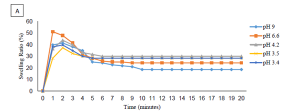
In response, Calcium Chloride concentrations were kept at 0.5%, and the amount of polymer used increased to 1.25%. The results can be seen in Figure 3a, Figure 3b, each sample labeled by pH. As the pH decreased toward 6 pH to 7 pH, the peak swelling ratio increased, as did the final swelling ratio. After this range, the peak and final swelling ratios decreased in value once again.
Figure 3a, Figure 3b are far from clear and are showing more than just the reaction between the SAP and Calcium ions. The direct effect of pH on the polymer is also a contributing factor. Removal of the effects of pH was done by finding the percent decrease in a sample from its maximum swelling ratio to its final swelling ratio. The results can be seen in Figure 4. A clear trend can now be seen; the percent change in swelling ratio from maximum to final values declined as pH declined. This implies that pH has the capability to significantly decrease the ability of divalent cations to react with the polymer, reducing the change from maximum to final swelling ratios from -55% at 9 pH to a range of -2% to -5% in an area of 0.5 pH to 0.75 pH. The ratio of polymer to Calcium also had an effect on the reaction. As the amount of SAP increased in the same Calcium brines, the change from peak to final swelling ratios decreased.


Figure 3 Swelling 1.25% AT-O3S in 0.5% Calcium Chloride at Varying Brine pH Values a) pH Value from 2.9 to 3.3 and b) pH Value from 3.4 to 9.
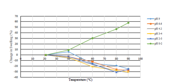
Modifications in sample temperature in almost all cases resulted in destabilization of the sample and further precipitation occurred, decreasing the swelling ratio by 15% to 30% at 90°C compared to the room temperature swelling ratio. In the range of 0 pH to 2 pH, temperature increases actually increased the swelling ratio of the polymer by almost 60% on average. Figures 5-7 through 7 show the effects of temperature on the test samples.

Figure 7 Percent Change in Swelling Ratio From Room Temperature 1.25% AT-O3S Polymer in 0.5% Calcium Chloride Brine.
Results for 2G-110 polymer
For the 2G-110 Polymer, the first tests were performed by varying pH levels for samples using 1.13% 2G-110 in 0.5% Calcium Chloride brines. Observing the results from the first tests, follow up trials were altered to use 1.25% 2G-110 while maintaining the 0.5% Calcium Chloride brine concentration.
The reactions of the 2G-110 polymer with the brine posed two problems, supposedly due to its particle size, in comparison to that of the AT-O3S. Due to the 2G-110’s smaller particle size, the time interval of the reactions that took place between the brine and the polymer were much faster due to having more surface area per unit volume, and since the particles were comparably smaller, they became easily suspended in the solution for a significant portion of the reaction time as well. As such, after performing the same steps used as those used for the AT-O3S polymer trials, only the 2G-110’s final swelling ratios were able to be accurately calculated after the solutions were allowed to settle for a significant time. The rest of the 2G-110’s trials using the heat bath mirrored that of the AT-O3S.
Observing the results in Figure 8, Figure 9, the effect of lowering the pH on the 2G-110 and brine solutions showed that, from the range of 2 pH and higher, the final swelling ratios appear to almost linearly decrease as pH was lowered across the trials, yet at a slight rate of decrease. However, at below 2 pH, the final swelling ratio significantly begins to drop.
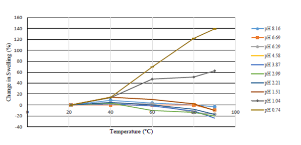
Through heating the solutions at varying temperatures, the samples with pH values greater than 2 destabilized and further precipitated when the temperature was raised higher than room temperature, as shown in Figure 10, Figure 11 where the data was grouped by alike pH’s. These samples experienced decreases in swelling ratios of around 5 to 20 percent, shown in Figure 12, when compared to the original swelling ratios of the samples. At pH levels of 2 and lower however, it was displayed that swelling ratios would range from relatively no change to significant increases of swelling ratios upwards of 140% as seen in Figures 10 through 12.

Figure 12: Percent Change in Swelling Ratio by Temperature 1.25% 2G-110 Polymer in 0.5% Calcium Chloride Brine.
pH has significant influence over the extent to which the polymer reacts with Calcium in solution, decreasing the effects of precipitation as pH decreases. A drop below a pH of 2 appears to result in negligible precipitation rates. As the pH of a solution decreases below 2 pH, precipitation effects become relatively insignificant at the investigated salinity and polymer concentration. It appears that pH has a significant effect on the precipitation of divalent cations and the polymer. Temperature had mixed effects on the polymer. At pH ranges over 2 pH, an increase in temperature resulted in a significant decrease in the swelling ratio and an increase in precipitation. At lower pH values, swelling ratios actually increased significantly. This implies that even at elevated temperatures, low pH prevents polymer destruction.
It is recommended to industry that, when confronted with the possibility of high concentrations of divalent cations, preflushes and acid washes should be performed prior to SAP treatments. Injection brines should be low pH to prevent post-swelling precipitation resulting from an increase in solution pH. The amount of polymer used should also be increased depending upon expected reservoir conditions. These considerations become increasingly important as temperature increases.
Funding for this project was provided by the Enhancing Undergraduate Research Endeavors and Creative Activities (EURECA) program at Midwestern State University. Most of this undergraduate research was conducted in Thermo fluids Lab in McCoy School of Engineering at Midwestern State University. The authors acknowledge the discussion and help of Professor Jianguo Shao in the Department of Chemistry at Midwestern State University.
The author declares no conflict of interest.

©2016 Elsharafi, et al. This is an open access article distributed under the terms of the, which permits unrestricted use, distribution, and build upon your work non-commercially.