International Journal of
eISSN: 2576-4454


Review Article Volume 3 Issue 4
1Department of Bioproducts and Biosystems Engineering, University of Minnesota, USA
2Department of Agricultural Engineering Technology, University of Wisconsin – River Falls,River Falls, USA
Correspondence: Joe Magner, Department of Bioproducts and Biosystems Engineering, University of Minnesota, USA
Received: July 14, 2019 | Published: July 16, 2019
Citation: Kramer G, Peterson J, Krider L, et al. Design and construction of an alternative drainage ditch system. Int J Hydro. 2019;3(4):259-268. DOI: 10.15406/ijh.2019.03.00188
Water quality in agricultural watersheds is under greater scrutiny as hydrologic pathways are altered to increase the production of affordable food. Fertilizers are widely used in these watersheds to obtain desirable levels of nitrogen and phosphorus for optimal crop growth. Some of these nutrients are transported from the field to natural channel systems. Agricultural drainage ditches often provide an important pathway in this movement of nutrients. Ditches have been traditionally designed to remove water from agricultural lands. Little attention has been placed on alternative designs that are inherently more stable, assimilate nutrients and provide healthy ecosystems. In 2009, 2000m of a conventional drainage ditch in southern Minnesota was converted to an alternative drainage system with a two-stage channel, a rock trench, a rock inlet, and two linear treatment systems. These features not only increase ditch stability but also provide storage and attenuate sediment and excess nutrients. This paper discusses the design and construction of this alternative drainage system.
Water quality in agricultural watersheds is under greater scrutiny as the landscape and hydrologic pathways are altered to increase the production of affordable food. Land use in southern Minnesota is largely row crop agricultural with the dominant crops being corn and soybean. In 2013, 8.5million acres of corn and 6.62million acres of soybeans were harvested in Minnesota.1 Each year, large quantities of nitrogen and phosphorous are applied to these crops to optimize yields. However, a portion of these nutrients are lost and transferred to major river systems in Minnesota and beyond. “On average, 211million pounds of TN [total nitrogen] leaves Minnesota each year in the Mississippi River at the Minnesota-Iowa border, with just over three-fourths of this load originating in Minnesota watersheds . . .,”.2 The phosphorus loading to surface waters from agricultural cropland for all of Minnesota’s 10 major drainage basins is estimated to be between 821,704 and 2,657,569kgyr-1, depending on whether it is a dry or wet year.3 The Mississippi River transports significant amounts of these nutrients to the Gulf of Mexico.
Excess nutrients introduced into natural systems can have major consequences for natural biological communities. Extensive drainage allows the useable forms of nitrogen and phosphorus for crop uptake to be transported to agricultural drainage ditches and natural channel systems. Excess growth of unwanted algae and duckweed (Lemna spp.) is often a consequence of excess nutrients agricultural runoff. The decomposition of algae and duckweed consumes large amounts of dissolved oxygen in the water column, creating hypoxic conditions (DO<2mgL-1) that are unsuitable for many plant and animal species, especially those that are particularly sensitive to low levels of dissolved oxygen. The hypoxic zone in the Gulf of Mexico is an example of this decomposition on a large scale. Alternative drainage ditches provide an opportunity to remove some of the nutrients before the water is discharged into natural channels.
Conventional drainage ditches are typically constructed as a trapezoidal channel, with a flat bottom and outside banks with a side slope ratio generally from 1:1 to 2:1 (horizontal: vertical).4 A cross-sectional view of this type of ditch is given in Figure 1. The depth of a conventional drainage ditch is usually designed to carry a flow with a recurrence interval from 5 to 100years.5 The trapezoidal shape of conventional drainage ditches can result in an over-widened channel bottom.6 A wide channel bottom greatly reduces flow velocity in the channel during low flow conditions, which leads to sediment aggradation.7,8 The sediment deposition can reduce the drainage capacity of ditches resulting in high maintenance (cleanout) costs.4,6‒8 Ditch cleanout disrupts the channel ecology9 by removing some or all of the existing vegetation and exposing bare soil. After deposited sediment is removed and the channel shape is returned to trapezoidal, the ditch will again begin its movement toward dynamic equilibrium.10 If the sediment supply is greater than the sediment transport capacity, sediment deposition will continue to occur, resulting in a cycle of high maintenance costs.
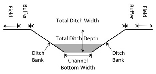
Figure 1 A Typical Conventional (Trapezoidal) Drainage Ditch Cross-Section.22
Traditional designs can lack consistent and sustainable amounts of plant biomass. However, the main problem that arises with the trapezoidal design, the toe slope of the ditch banks are continuously exposed to boundary shear forces.11,12 This continuous exposure leads to reduced soil strength along the toe of the ditch bank (bank/bed interface) and can cause mass wasting and bank sloughing.11,12 The traditional design does not provide adequate habitat for aquatic organisms. The dominance of finer bed material, lack of pool-riffle sequences and shallow pool depth are common characteristics of the trapezoidal ditch that negatively affect biotic integrity.
Two-stage drainage ditches are designed to mimic the stable conditions found in natural low-order streams.1,11 They are usually constructed to replace conventional ditches and are most beneficial at sites where present conventional drainage ditches are unstable and require clean out often. A low-flow channel is sized to replicate that of a natural channel (in the surrounding region) with similar drainage area. Two-stage channels are designed with small benches on both sides of the low-flow channel to serve as a floodplain. The benches allow for dissipation of the fluvial energy associated with high flow rates.11 A schematic of a two-stage ditch is given in Figure 2. Alternatively designed agricultural drainage ditches help facilitate higher levels of denitrification, one of the key processes for permanently removing nitrates from natural systems.13 As water level exceeds the bankfull depth during storm events, the flow spreads out across the floodplains. This has the effect of slowing water velocity, increasing water residence times, and reducing nitrogen transport during large flow events Plant biomass serves as an important carbon source necessary to support denitrifying bacteria. Two-stage ditches have benches that support more than twice the amount of biomass compared to the slopes of the traditional drainage ditch.13,14 This vegetative cover not only increases nutrient uptake but may also provide more shade for fish in the narrower low-flow channel and increase evapotranspiration.11,13,14 Improved fish habitat is expected because of improved sediment sorting, with fine materials either carried away by the low-flow channel or deposited on the benches, and coarse materials are allowed to settle in the channel bed, as well as the presence of deeper water during low-flow periods.5,11,14
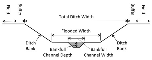
Figure 2 A Two-Stage Drainage Ditch Cross-Section.22
The main value of a two-stage ditch is increased stability in the ditch system. This is mainly embodied in reduced ditch cleanout costs associated with sediment deposition.4,5,14 Additionally, a reduction in erosive forces at the toe of the outer ditch bank is expected, as water will usually be confined to the low-flow channel.5 Increased stability at the toe of the ditch will also likely reduce the potential for sloughing and mass wasting on the outside ditch banks. This design is also wider than the traditional design and can provide storage during storm events depending on the downstream control (e.g. culvert size).
Over the past half century, engineers and earth scientists,15-17 have sought to explain river variability and provide a method for describing or classifying riverine systems. Natural streams tend to meander where the stream slope is too flat to carry sediment. Further, meanders move with time and can adjust to different or evolved stream types. Stream classification methods are mostly oriented toward natural, wild-land streams in non-developed areas and not for drainage ditches designed for use in developed agricultural landscapes. However, Simon and Hupp18 created a conceptual model of channel evolution for a natural stream that was converted to a trapezoidal channel illustrating six stages of bank-slope development (Figure 3).
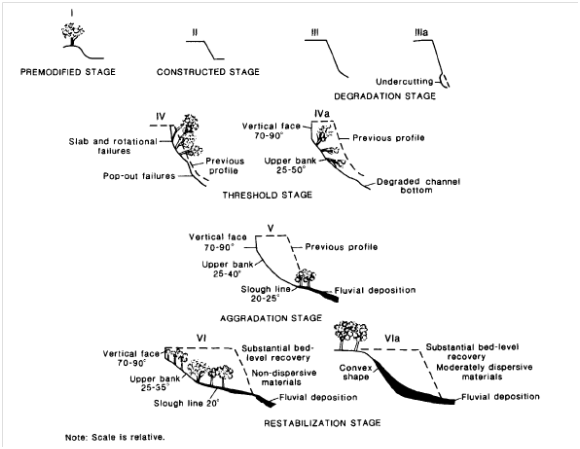
Figure 3 Simon & Hupp Six Stages of Bank-Slope Development.22
The first stage, (I) Premodified Stage, has stable banks, with minimal aggradation, basal erosion on outside bends, deposition on inside bends, and a meandering channel. Bank conditions are the result of natural fluvial processes associated with the channel forming flow.19 The second or (II) Constructed Stage, typically involves the removal of vegetation, excavation, and reshaping the existing channel banks to a trapezoidal shape and even repositioning of the channel to enhance water drainage to maximize crop production. Banks are generally steepened and heightened, with respect to the channel forming flow, to contain frequent peak flows and prevent cropland flooding. Simon and Hupp18 developed the constructed stage based on observations of channelization in low gradient regions of the Midwestern USA.
The third stage, (III) Degradation Stage, is marked by rapid erosion (downcutting) on the channel bed, and basal erosion on the banks, resulting in higher and steeper banks. Stage four, (IV) Threshold Stage, results from continued degradation as the channel enlarges. In cohesive soils, mass wasting processes occur and the stream bed over-widens but at a new, lower base elevation. Stage five, (V) Aggradation Stage, is marked by aggradation on the over-wide channel bed, beginning downstream and progressing upstream over time. Bank stability begins to improve because the bank angle becomes less steep and a meandering low-flow thalweg with channel bars may develop within the new channel geometry if there is a supply of sediment. Typically, Midwestern ditches set in glacial till have limited sediment supply and do not fully regrade as described.12 The final stage, (VI) Restabilization Stage, is marked by further development of the meandering thalweg, continued deposition and stabilization of alternate channel bars, and the re-establishment of vegetation within the constructed channel geometry. Again, this assumes a sediment supply for the aggradation process. Fine sediment remains suspended and typically gets expanded downstream. The Simon and Hupp channel evolution model (CEM) is a useful model with respect to channelization for the prediction of how channelized streams will respond over time to changes in channel geometry. These processes are generally applicable to constructed agricultural drainage ditches. However, for agricultural drainage ditches, the widening of the channels represents a loss of productive soil from adjacent farmlands via bank erosion.
The Mullenbach Drainage Ditch is a privately-owned system used for our study. This ditch is located in rural Mower County in southern Minnesota, USA, approximately 8km southwest of the town of Adams, MN, and 10km south-southeast of the town of Rose Creek, MN (Figure 4). It is in the headwaters of the Little Cedar River within the Upper Cedar River Watershed (8-digit HUC: 07080201). The Mullenbach Ditch empties into the Little Cedar River approximately 4km downstream of the constructed two-stage ditch reach, which then flows south into the state of Iowa. The watershed area is 12.6km2 (3,102acres) and the land use is predominantly row crop agriculture. The Mullenbach Drainage Ditch was selected for conversion to a two-stage ditch for a number of reasons. First, the existing trapezoidal ditch was scheduled for maintenance during 2009 or 2010 due to several instabilities within the ditch system including the following: 1) bank instability caused by seepage; 2) planar failure and toe erosion in ditch banks; and 3) tile outlet failures. Second, the Mullenbach site was identified as one where the landowners surrounding the ditch were supportive of the project. With funding and assistance from The Nature Conservancy and the Mower County Soil and Water Conservation District, approximately 2000m of the Mullenbach Drainage Ditch was converted to the two-stage design in October of 2009.
The success and desired results of a two-stage ditch significantly depend upon the site location and preconstruction analysis. Not all sites are suitable for the construction of a two-stage ditch. A series of factors determine the feasibility of a two-stage ditch: channel slope, be and bank soil, and construction costs. Two-stage channel systems consist of an inset channel (1st Stage) to convey the bankfull or channel forming discharge and attached benches or shelves (2nd Stage) as that serves as a floodplain to aid in sustaining dynamic equilibrium in the system (Figure 2). Agricultural fields, woods, pastures, roads, and areas associated with human activities adjacent to the ditch (the top of the 2-stage system) are important because: (1) runoff from these areas might cause erosion problems; (2) they are the upper boundary of the system that influences bank stability; (3) excavated material is often placed in these areas; and (4) in agricultural settings, this is where edge of field Best Management Practices (BMP) are located.
The desired soil type for a two-stage ditch is a fertile cohesive soil. Cohesive soils are defined as soil with high clay content and can maintain cohesive properties while submerged.20 The cohesive properties of the soil impact the inset channel, erodibility, sediment transport, bank slopes stability and bench stability.13 The desired soil class is a class A with the textural triangle classes of clay, silty clay, clay loam, silty clay loam and sandy clay loam.20 This type of soil makes it feasible to create a 1:1 inset channel slope and a 2:1 bank slope to allow for more vegetative growth. The fertility of the soil contributes to the vegetative growth along the banks and benches which further stabilizes the ditch. Wooded vegetation along the banks of the ditch decreases the stability of the banks from erosion. Erosion is commonly noted along two-stage ditches with wooded edges.21 Land availability is another factor in determining the suitability for a two-stage ditch. Creating undersized benches or a 1-sided, two-stage ditch should be avoided. Areas of avoidance include ditches between two landowners without dual compliance, salvaging costs by only digging one side, trying to run a ditch along a wooded edge, and compromising with the natural sinusoidal stream path.21 A gradual topography is more suitable for a two-stage ditch than a flat terrain. Land usage contributes significantly to factors in determining optimum two-stage site locations. Inclusion of tile outlet needs to be done very carefully. Tile outlets locations need to be noted and accounted for to prevent altered flow, erosion, and scours. The height of the tile outlets need to be near the elevation of the benches and protected with riprap flush with the benches.
Preliminary ditch assessment can be done using the MADRAS.10 to assess conditions. MADRAS (Mn Ag-Ditch Reach Assessment for Stability) is a relatively rapid assessment tool that considers both channel hydraulics and geotechnical factors associated with channel instability. A ditch reach must be walked by an evaluator to gather field evidence and determine processes such as toe slope erosion, bank seepage, bank angle, vegetation, slumping, and the relative in-channel sediment storage and transport. Observations of physical processes and hydrologic pathways are documented and then interpreted to diagnosis the ditch condition. Localized ground water seepage-induced slumps require a different solution compared to bank slumping induced by systematic hydrologic changes within a watershed. Ditch reach assessment offers the local drainage authority a means to define and prioritize the nature of ditch channel instability and a framework for guiding the maintenance response to unstable ditches. Though MADRAS was designed for Minnesota ditches, it can be adapted to any location by altering the scoring sheets.
Sizing a two-stage ditch
Sizing a two-stage channel involves determining the bench height; sizing the flooded width at the bankfull elevation of the inset channel; and determining the channel side slope for the second stage. The floodplain width includes the two constructed benches and the channel width (Figure 3).22 The elevation and size of the benches should be based on data collection and analyses associated with a weight-of-evidence approach; ideally, the analysis should use published regional hydraulic geometry relationships for agricultural ditches, or the development and use of these relationships to provide estimates of the expected inset channel dimensions.5,12 These relationships relate drainage area to the width, depth and cross-sectional area of the inset channel that might naturally occur in the ditch. In the area, published regional relationships for natural streams may have larger dimensions than those for ditches and their use in ditches might result in an inset channel that could be too wide to effectively transport the sediment load. Bench flooding will likely be an issue if overbank flooding is a desired goal because of seldom flood activity and possible limited water quality benefits. Estimates from the regional relationships should be compared with actual measured fluvial features at the project site, the reference reach, hydrologic estimates, shear stress depth, and estimated bankfull/effective discharge depth. If there is good agreement between all of these factors then the likelihood of project success is high and the two-stage ditch design should proceed.
Additional guidance
The location, purpose (associated land use), climate, geologic material and terrain, vegetation and concordant management all play a role in ditch performance and the potential to meander over time. A typical road ditch provides a place for runoff and hopefully prevents water accumulation on the road. Often these ditches only flow during storm events or during the April soil thaw. In contrast, most agricultural ditches carry water and sediment year round because they are an intrinsic part of the watershed drainage system. In cropland regions, the primary objective of the ditch is to keep row crop fields dry by lowering the water table or providing a pathway to direct surface runoff away from fields. The size of agricultural ditches can vary from less than 2km2 to large systems found in the Red River basin (>200km2). The perennial presence of water is also influenced by climate and geology. Ditches in western MN and the Dakotas often have wetland vegetation growing in the bed due to less precipitation, more evapotranspiration, and clay content. Ditches in southern MN and Iowa have scoured beds with a range of substrates (clay to gravel). All ditches should be vegetated, typically with grasses; however, if not maintained over time, woody species can take root along ditch banks. Woody vegetation is typically undesirable because of increased channel roughness and difficulty associated with clean-out. Once a ditch is constructed, management determines the long-term viability and performance. Some ditches are more costly to maintain; whereas, other ditches remain stable over time or evolve to a stable form depending on the geology and/or changes in the contributing drainage area hydrology.
Two-stage ditch design
Channel depth and width for each of the two stages are important design parameters. The low-flow channel dimensions were calculated according to regional curves previously developed by Drs. Joseph Magner and Ken Brooks for south-central Minnesota. Figure 5 provides a design curve for southern Minnesota bankfull channel cross-sectional areas, or inset channel. This figure presents three curves; 1) cross-sectional area (A), 2) cross-sectional width (W) and 3) cross-sectional depth (D). This curve can be used as a starting point to evaluate if the state of a given inset channel is stable or transitioning to an unstable form. In many instances, a clear inset channel is not evident and a regional hydraulic geometry curve developed from field measurements must be used to estimate bankfull. Figure 6 illustrates the wide range of cross-sectional areas that occur for an array of channel types found across Minnesota. Because channel cross-sectional areas vary by climate and stream type, as illustrated by the relatively low R-squared in Figure 6, we recommend the more targeted regional curve presented in Figure 5 to guide two-stage channel design in southern Minnesota. However, if you are located in central or northern Minnesota, Figure 6 will provide a benchmark for selecting an appropriate inset channel.
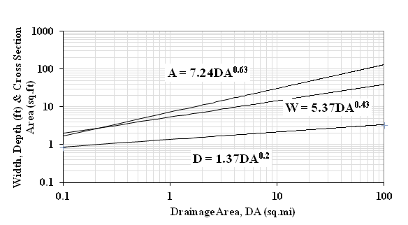
Figure 5 Regional Hydraulic Geometry Curve for sizing low-flow or inset channels in Southern Minnesota Ditches.
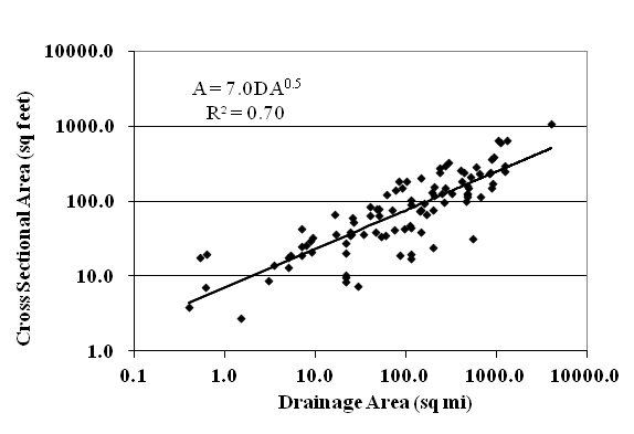
Figure 6 Minnesota Regional Hydraulic Geometry Curve for a wide range of channel types (a broad estimate of the bankfull channel area).
In systems with cohesive bank materials that can readily be vegetated with grasses, the ratio of the flooded width to the inset channel width should be 3:1 to 5:1. The bench elevation corresponds to the height above the channel bed as estimated by the inset channel depth; the existing bank will be excavated at the bench elevation. In cohesive soils, the inset channel side slopes typically form at slopes steeper than 1.5 to 1. In the 2nd stage of the channel, side slopes should be constructed at 2:1 or flatter slopes. Side slopes need to be stable so slump failures do not occur during high flow events. By constructing benches, and perhaps flatter slopes, the conveyance capacity of the modified ditch will be greater than the existing trapezoidal channel. If there is a need to further increase conveyance to satisfy an extreme discharge design requirement or to provide flood storage, this can be accomplished by increasing the bench widths or further flattening the side slopes of the 2nd stage. Wider benches should provide more fluvial and ecosystem benefits but also increase the potential for the inset channel to meander and encroach on the banks of the 2nd stage. The potential to meander or encroach on the second bank is a function of several factors.
The two-stage channel design was performed using The Reference Reach Spreadsheet developed by Mecklenburg and Ward,23 where the recommended ratio of flooded width to low-flow channel width is between 3:1 and 5:1.5,13 At the Mullenbach site, the minimum recommended ratio of 3:1 was used, in order to reduce excavation costs and reduce the land loss of adjacent agricultural fields. The outside ditch bank slope was designed at 2:1. Approximately 80 percent of the existing low flow channel prior to constructions was within the design specifications of 2.5 to 3.5 meters. To reduce the amount of sediment disturbed during the construction process and preserve the vegetation growing along the edge of the low flow channel 80% of the low flow channel was left intact. Where the existing channel was over widened, soil was added to one side of the low flow channel to match the design width of 2 meters. Key channel dimensions are given in Table 1. A typical cross-section is given in Figure 7.
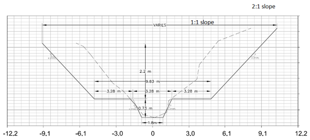
Figure 7 Typical Cross-Section Showing Pre-existing and Two-Stage Channel Design Dimensions. The Existing (Before Construction) Channel Cross-Section is Shown by the Dashed Line. All Dimensions are in Meters. Drawing by Joel Peterson.
Channel feature |
Designed(m) |
Constructed(m) |
Low-flow channel depth |
0.57 |
Approximately 0.61(varies with bed) |
Low-flow channel top width |
3.28 |
2.74 to 3.35 |
Low-flow channel cross-sectional area |
6.06 |
Varies throughout reach |
Bench width |
3.28 |
2.74 to 3.35 |
Flooded width |
9.83 |
9.75 |
Overall ditch top width (approximate) |
19.2 |
19.2 |
Table 1 Design and constructed channel dimensions
Characteristics of the mullenbach drainage ditch site
There are 16 subsurface tile drainage outlets that discharge into the ditch reach between 120th Street and Mower County Highway 6 (Figure 8). In an effort to improve the nutrient removal capabilities of the two-stage ditch system, two of the 16 tile outlets were constructed with bench treatment systems. There are also 12 side inlets (Figure 8), which are designed to convey surface water from the surrounding landscape into the ditch. All of the side inlets were replaced during construction, and each was sized according to the area from which it receives surface runoff. A schematic of the design of a typical side inlet is given in Figure 9. A rock (trench) side inlet was used instead of the standard design for one of the side inlets.
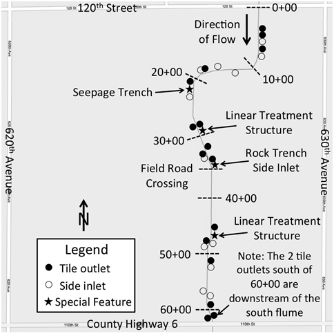
Figure 8 Map of the Mullenbach Two-Stage Drainage Ditch Site Showing the Locations of Ditch Structures. Markers Indicate the Distance (in feet) Downstream from the North End of the Project Reach, and Special Features are Labeled within the Map. Base Map ©Google.
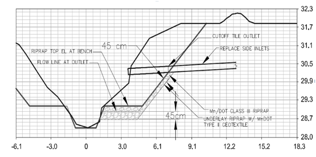
Figure 9 Schematic Showing the Construction Modifications to Each Tile Outlet. Dimensions are in Centimeters. Drawing by Joel Peterson.
A number of wells were placed near and within the ditch to better understand the groundwater flow and its contributions to the chemical composition of water within the ditch. The locations of the groundwater monitoring stations are shown in Figure 8. Starting at the north flume, groundwater wells were installed every ~366m. Most of the wells were installed at the toe of the ditch bank along the benches, with the exception of one on the terrace (1+50) and one in the channel (53+00). Between stations 50+00 and 54+40 was an area with high groundwater contribution; a number of shallow and deeper wells were installed between 51+00 and 53+00 to investigate this area more thoroughly for high nitrates in the groundwater discharge (Figure 8). Erosion control was obtained by anchoring erosion control blankets along the channel benches and outside slopes. Blankets were installed by a subcontractor selected by the construction company. All erosion control blankets were selected following Minnesota Department of Transportation guidelines.24 A total of 500yd2 (418m2) and 210yd2 (176m2) of Category 3 and Category 2,24 geotextile blankets were used in the installation of riprap below side inlets and tile outlets. 48,400yd2 (40,500m2) of MnDOT Category 2 erosion control blankets were used to line the exposed ditch benches and outside ditch banks following construction. A BWSR seed mixture of 19 native grasses and forbs was applied to the soil, with an additional rye seeding in November of 2009 in an attempt to better establish vegetation before the winter season.
Because of the wider channel for two-stage ditches, water from tile outlets can be directed to treatment systems located on the benches. These treatment systems have the potential to remove nutrients. Two experimental bench treatment systems were constructed for the Mullenbach Ditch as a water quality improvement measure. Instead of discharging the flow from the tile outlets to the low flow channel, tile flows for these systems were routed to a 61-m long constructed channel along the outside of the ditch bench (adjacent to the outside ditch bank). After the water flows through the constructed treatment system for 61m, the channel is routed across the bench toward the low-flow channel, through a reinforced riprap section, where the water empties into the low-flow channel. The intent of the linear treatment structures is to enhance nutrient reduction in tile outlet water by increasing residence time and water-plant contact. A design schematic for constructing a tile outlet to a bench treatment structure is shown in Figure 10. A photograph of the bench treatment system (location 28+00) shortly after construction is shown in Figure 11.
During construction of ditches, material excavated from the ditch are typically placed on the field edge and eventually spread out along the sides of the ditch. A relatively small soil berm on top of the ditch bank is usually created. Water is ponded behind this berm in depressional areas located next to the ditch. Side inlets are installed to discharge the ponded water to the drainage ditch. As previously discussed, traditional open pipe side inlet design was used for twelve of the inlets (Figure 8). However at station 35+25, a rock inlet design was installed. For this design, water and sediment (and sediment-bound pollutants) is filtered through a rock bed before it flows into the ditch. The infiltration rate through the rock is lower than that of an open pipe resulting in ponded water at the field edge during high runoff events. During the time of ponding some of the sediment load can settle out and a small amount of sediment could also be trapped in the rock filter, thus potentially reducing the sediment load to the ditch or stream. The rock inlet was also sized so that ponded water is discharged rapidly enough to minimize damage to the crops.
Schematics of the rock side inlet at station 35+25 are shown in Figures 12&13. A photograph showing the rock inlet is given in Figure 14. To allow the capture of seepage flow, the rock trench extended to a distance of 1.83m below the ground surface. The rock trench of the inlet was constructed parallel to the channel and at a length of 6.1m and a width of 0.91m. The rock trench was filled with 1.9cm to 3.81cm gravel to a height of 6 in above the soil surface. An auxiliary surface tile inlet (24 in diameter) was included, with an inlet elevation 15.24cm higher than the soil surface. This structure allows water to bypass the rock trench during high runoff events. The rock side inlet outlets to a horizontal pipe, which enters the ditch bench on an armored surface.
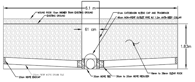
Figure 12 Side View of the Rock Trench Side Inlet. Dimensions in Meters and Centimeters. Drawing by Joel Peterson.
Bank geotechnical failure can be a problem for drainage ditches constructed in fields with high water tables. Seepage forces can contribute to bank sloughing into the bed. An alternative design feature that can be used to reduce these seepage forces is seepage trench. This trench intercepts groundwater flow and safely discharges it into the ditch. Schematics of the seepage trench used for this project are shown in Figures 15& 16. Figure 17 shows the seepage trench during construction. The trench was designed to intercept ground water and lower the water table to an elevation near the toe of the ditch bank. The dimensions of the seepage trench are 30.5m long by 0.91m wide and 1.22m deep. The top of the rock is 0.61m below the soil surface. The trench was filled with rock with a diameter of 1.91 to 3.81cm. A perforated 20.32cm plastic collector pipe is located in the middle of the seepage trench at the bottom to carry intercepted water to the seepage trench outlet pipe. The outlet pipe (30.5cm plastic) was laid perpendicular to the seepage trench to carry water through the ditch bank and into the channel. Riprap armoring was used beneath the outlet pipe and across the ditch bench to minimize scour and erosion. The trench is parallel to the ditch channel and is located 1.22m west of the top of the ditch.
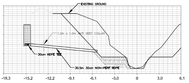
Figure 15 Two-Stage Channel Cross-Section Showing the Seepage Trench. Dimensions of the Axis are in Meters and Centimeters. Drawing by Joel Peterson.
With funds and local landowner and water resource manager support, conventional drainage ditches can be converted to alternative drainage systems. However, not all locations have suitable soils, land use, and land availability to make a two-stage system feasible. A preliminary assessment using MADRAS to assess ditch stability is recommended. Regional curves can be used to appropriately size a two-stage ditch and other structures can be retrofitted to provide additional water quality benefits. Mecklenburg and Ward’s Reference Reach Spreadsheet can be used to design specific two–stage ditches. Construction costs and an economic analysis are described in (other publication) and the resulting fluvial geomorphological characteristics as well as physical stability over time and its effect on the biological community are presented in (other paper).
The authors declares that there is no conflicts of interest

©2019 Kramer, et al. This is an open access article distributed under the terms of the, which permits unrestricted use, distribution, and build upon your work non-commercially.