International Journal of
eISSN: 2573-2838


Research Article Volume 8 Issue 1
Department of Technological Machines and Equipment, Branch of the National Research University “MPEI” in Smolensk, Smolensk, Russia
Correspondence: Borisov A, Department of Technological Machines and Equipment, Branch of the National Research University “MPEI” in Smolensk, Smolensk, Russia
Received: April 15, 2022 | Published: May 4, 2023
Citation: Borisov A, Blinov A, Konchina L, et al. Electromechanical model of exoskeleton with three mobile links. Int J Biosen Bioelectron. 2023;8(1):32-37. DOI: 10.15406/ijbsbe.2023.08.00229
The article considers an electromechanical model of an exoskeleton with three links, for which a system of differential equations of motion is written and inverse and direct problems of dynamics are solved. The angles between the links that specify anthropoid motion are figured out analytically. The electric drive controlling torques are found as a result of solving the inverse dynamics problem. The found torques are approximated with stepwise piecewise-constant functions simulating the impulse control of the exoskeleton motion. The solution of the direct problem of dynamics is carried out and the link rotation angles as functions of time are found. The results of the numerical solution of the system of differential equations are compared with the initial motion of the links. It has been found that the results of simulation with impulse control are in good agreement with the original motion. The total energy expenditures have been calculated. The exoskeleton simulation, taking into account the electric drive impacts also has been carried out. For this purpose, a system of differential equations of motion has been compiled; a numerical solution of the Cauchy problem for the compiled system has been carried out. The significance of the electric drive impact on the dynamics of the mechanism has been confirmed.
Keywords: exoskeleton, electric drives, local coordinate systems, control torques
Designing mathematical model of three-link exoskeleton is an actual line of research, since this model can prove to be more precise and lifelike than the models with the lower number of links. A more precise model can facilitate the understanding of interaction between exoskeleton and human body. It can also help developers in designing more effective and comfortable exoskeletons. The three-link model can take into account a more complex geometry of exoskeleton links and can describe their interaction during exoskeleton motion more precisely. It can enhance the predictive capabilities of the model, and help designers in creating more accurate and comfortable exoskeletons. It can also encourage scientific research in mechanics and biomechanics, which can lead to further enhancing of exoskeleton technologies and creating more effective solutions for people with disabilities. The exoskeleton models, previously developed by the authors, are presented in the papers.1–4 The issues of simulating exoskeletons and anthropoid mechanisms with various actuators, including electric drives, are covered in the papers.5–10 The studies are focused on some exoskeleton applications. These papers provide relevance and importance of exoskeleton development.11,12
Electromechanical model description for a three-link exoskeleton with the angles calculated between the links
For identifying the mechanism behavior patterns while building the system of differential equations of motion, consider a three-link model with the angles calculated between the links and four systems of coordinates – one of which is absolute and three of which are local (Figure 1). Let's introduce the absolute right-hand Cartesian coordinate system A0xyz with the plane xA0Y , in which the exoskeleton motion takes place (Figure 1). Let's introduce the mobile local system of coordinates A0x1y1 , which is fixed to the first bottom link A0A1 , for describing its motion. The mobile axis Ax01 is directed along the link; the axis A0y1 is introduced based on the right-hand basis. The local system of coordinates for the second and the third link is introduced in a similar way. The exoskeleton model consists of three absolutely rigid weighty links simulated by rods (Figure 1). The links are coupled with cylindrical hinges at the points A0 , A1 , and A2 . The cylindrical hinge at the point A0 is firmly fixed to the supporting surface. The lengths of the links are as follows: A0A1=l1 , A1A2=l2 , A2A=3l3 . The links are linear rods; they are considered unchanged during mechanism motion, and under any applied forces. The mass of the first link A0A1 equals to m1 , the mass of the second link A1A2 equals to m2 , the mass of the third link A2A3 equals to m3 . Since in the selected mechanism model the links are assumed to be absolutely rigid weighty rods, their moments of inertia are calculated as those for the homogeneous solid rods. The moment of inertia of the link A0A1 about the axis passing through its beginning, the point A0 perpendicular to the motion plane x1A0Y1 , is denoted I1 . The moments of inertia of the second and the third links are denoted I2 and I3 respectively. The first link A0A1 performs rotational motion about the axis in the cylindrical hinge A0 . The link position depends on just one parameter and is determined by the angle φ1(t) . Let's use M1 to denote the controlling torque developed in the hinge A0 . The position of the second link A1A2 that performs the plane-parallel motion depends on the motion of the point M2 , which is regarded as a pole, and on one additional parameter, the angle φ2(t) . The same is true for the third link. The hinge A2 is considered as a pole. The link position also depends on the angle φ3(t) . Let's use M2 and M3 to denote controlling torque at the hinge A1 , and at the hinge A2 respectively (Figure 1).
The generalized coordinates clearly describing the mechanism position in the plane are the angles between the corresponding axes of coordinates Figure 1: φ1(t) , φ2(t) , φ3(t) . The considered system has three degrees of freedom. Three independent drives should be used for implementing the controlled motion, i.e. to control the rotation angle of each link. Electric motors are used in the study. The electric motors, controlling the angular coordinates, are coupled with reduction gears decreasing the turnovers and increasing the torques.
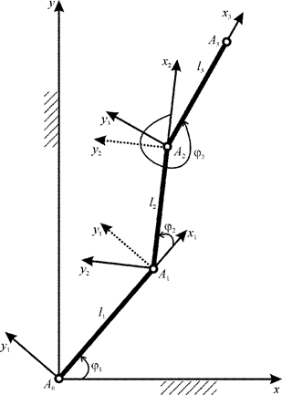
Figure 1 The model of the mechanism with three mobile links and local systems of coordinates, moving in the vertical plane.
The kinetic energy of the mechanism has been recorded, which includes the motion energy of the links A0A1 , A1A2 , and A2A3 :
T=TA0A1+TA1A2+TA2A3==12[(I1+I2+I3+(m2+m3)l21+m3l22+(m2+2m3)l1l2cosϕ2+m3l2l3cosϕ3++m3l1l3cos(ϕ2+ϕ3))˙ϕ21+(I2+I3+m3l22+m3l2l3cosϕ3)˙ϕ22+I3˙ϕ23++(2I2+2I3+2m3l22+(m2+2m3)l1l2cosϕ2+2m3l2l3cosϕ3+m3l1l3cos(ϕ2+ϕ3))˙ϕ1˙ϕ2++(2I3+m3l2l3cosϕ3+m3l1l3cos(ϕ2+ϕ3))˙ϕ1˙ϕ3+(2I3+m3l2l3cosϕ3)˙ϕ2˙ϕ3] (1)
The system of differential equations of motion for the three-link exoskeleton model has been composed using the software for building the system of differential equations of motion
(I1+I2+I3+(m2+m3)l21+m3l22+(m2+2m3)l1l2cosϕ2+m3l3(l2cosϕ3+l1cos(ϕ2+ϕ3)))¨ϕ1++(I2+I3+m3l22+(12m2+m3)l1l2cosϕ2+m3l3(l2cosϕ3+12l1cos(ϕ2+ϕ3)))¨ϕ2++(I3+12m3l2l3cosϕ3+12m3l1l3cos(ϕ2+ϕ3))¨ϕ3−l1((12m2+m3)l2(sinϕ2)+12m3l3sin(ϕ2+ϕ3))˙ϕ22−−12m3l3(l2(sinϕ3)+l1sin(ϕ2+ϕ3))˙ϕ23−[(m2+2m3)l1l2(sinϕ2)−m3l1l3sin(ϕ2+ϕ3)]˙ϕ1˙ϕ2−−m3l3(l2(sinϕ3)+l1sin(ϕ2+ϕ3))˙ϕ1˙ϕ3−m3l3(l2(sinϕ3)+l1sin(ϕ2+ϕ3))˙ϕ2˙ϕ3++g[(12m1+m2+m3)l1cosϕ1+(12m2+m3)l2cos(ϕ1+ϕ2)+12m3l3cos(ϕ1+ϕ2+ϕ3)]=M1−M2,(I2+I3+m3l22+(12m2+m3)l1l2cosϕ2+m3l3(l2cosϕ3+12l1cos(ϕ2+ϕ3)))¨ϕ1++(I2+I3+m3l22+m3l2l3cosϕ3)¨ϕ2+(I3+12m3l2l3cosϕ3)¨ϕ3++l1((12m2+m3)l2(sinϕ2)+12m3l3sin(ϕ2+ϕ3))˙ϕ21−12m3l2l3(sinϕ3)˙ϕ23−m3l2l3(sinϕ3)˙ϕ1˙ϕ3−−m3l2l3(sinϕ3)˙ϕ2˙ϕ3+g[(12m2+m3)l2cos(ϕ1+ϕ2)+12m3l3cos(ϕ1+ϕ2+ϕ3)]=M2−M3,(I3+12m3l2l3cosϕ3+12m3l1l3cos(ϕ2+ϕ3))¨ϕ1+(I3+12m3l2l3cosϕ3)¨ϕ2+I3¨ϕ3++12m3l3(l2sinϕ3+l1sin(ϕ2+ϕ3))˙ϕ21+12m3l2l3(sinϕ3)˙ϕ22++m3l2l3(sinϕ3)˙ϕ1˙ϕ2+12gm3l3cos(ϕ1+ϕ2+ϕ3)=M3. (2)
Thus, the system of differential equations of motion in the form of Lagrange equations of the second kind that form the mathematical model of the three-link exoskeleton has been created. Thereafter, this system is used for the simulation of mechanism motion.
The electric motor rotor impact assessment on the dynamics of electromechanical model of the three-link exoskeleton:
Let’s analyze the electric motor rotor impact on the dynamics of the three-link exoskeleton model.2 Consider electromechanical model of the link drives that includes electric motors with reduction gears located at the hinges Ai−1 (i = 1,2,3). Taking into consideration the rotating rotors of electric motors and their masses, the kinetic energy expression (1) is transformed into the following:
T=12[(I1+IR1k2R1+I2+I3+(m2+mE2+m3+mE3)l21+(m3+mE3)l22++(m2+2m3+2mE3)l1l2cosϕ2+m3l2l3cosϕ3++m3l1l3cos(ϕ2+ϕ3))˙ϕ21+(I2+IR2k2R2+I3+(m3+mE3)l22+m3l2l3cosϕ3)˙ϕ22+(I3+IR3k2R3)˙ϕ23++(2I2+2I3+2(m3+mE3)l22+(m2+2m3+2mE3)l1l2cosϕ2+2m3l2l3cosϕ3+m3l1l3cos(ϕ2+ϕ3))˙ϕ1˙ϕ2++(2I3+m3l2l3cosϕ3+m3l1l3cos(ϕ2+ϕ3))˙ϕ1˙ϕ3+(2I3+m3l2l3cosϕ3)˙ϕ2˙ϕ3] (3)
Where IRi is the moment of inertia of the rotor of the electric motor relative to the axis of rotation, kRi is the gear ratio of the gearbox, number 1 refers to the drive in the A0 joint, number 2 - in the A1 joint, number 3 - in the A2 joint.
Analyzing the structure of kinetic energy expression (3), and comparing it with the expression (1), it can be observed that the differences, in case of taking into account the inertial properties of the electric drives, are limited to extra terms in parentheses. These terms include moments of inertia and masses equal to those of electric drives. The pattern of kinetic energy expression for the mechanism stays the same. The system of differential equations of motion (2) is changed in a similar way. This system is not listed here.
Inverse dynamics problem solution
Let's find the controlling torques required for specifying the anthropomorphic motion of the considered three-link exoskeleton. These torques are required for selecting electric drives with reduction gears. For this purpose, let's use the system of differential equations of motion (2). It is assumed that the exoskeleton simulates the shin with the hip of the supporting leg, and the human body. Let's find analytically the angles between the links, i.e. between the axes of the local systems of coordinates, in the form of periodic functions specifying anthropoid motion of the three considered links in the absolute system of coordinates:
φ1(t)=π/2+a1j1sin[f1–(1–cos[2πt/T])π/2],φ2(t) =a2(j2cos[f2–π(1–cos[2πt/T])π/2]/2–j1sin[f1–(1–cos[2πt/T])π/2]),φ3(t) =a3(j3sin[f2–π(1+cos[2πt/T])π/2] ––(j2cos[f2–π(1–cos[2πt/T])π/2]/2–j1sin[f1–(1–cos[2πt/T])π/2]). (4)
Where Т – the walk period, ai,ji, and fi – the walk parameters (i = 1,…,5).
Let's select the values of mechanism properties corresponding to those of the human shin (subscript 1), human hip (subscript 2), and the human body (subscript 3). The information about these values can be found in the monograph.1 The lengths of the links are as follows: I1=0.385m,I2=0.477m,I3=0.771m . The masses of the links are as follows: m1=2.91 kg, m2= 8.93 kg, m3= 28.93 kg. The moment of inertia of the link is calculated based on the formula for that of the rod about the axis passing perpendicularly through its end. These moments are as follows: I1=0.144 kg·m2, I2=0.677 kg·m2, I3=5.732 kg·m2. The acceleration due to gravity is g=9.81 m/s2. The time span of the single-support step phase, i.e. the half of the walk period is tk=0.36 s. The parameters of the walk are as follows: a1=1,a2=0.11,a3=0.4,j1=j2=0.25,j3=0.1,f1=π/2,f2=0.687 .
The curves representing the link rotation angles (3), angular velocities, and angular accelerations are presented in the Figure 2. Several frames of the three-link exoskeleton motion animation are given below (Figure 3).
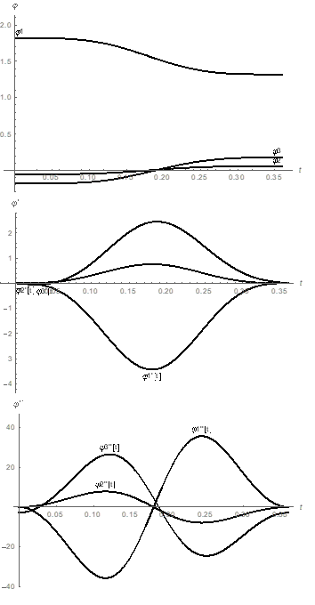
Figure 2 The curves representing rotation angles ϕ1,ϕ2,ϕ3 (rad), angular velocities ˙ϕ1,˙ϕ2,˙ϕ3 (rad/s), and angular accelerations ¨ϕ1,¨ϕ2,¨ϕ3 (rad/s2) of the links as functions of time t (s).
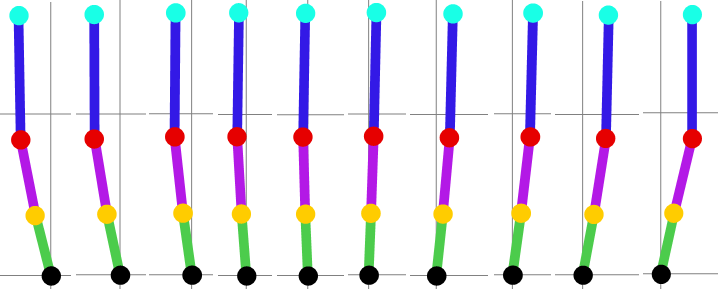
Figure 3 Animation frames of the three-link exoskeleton motion specified by the angles ϕ1,ϕ2,ϕ3 based on the formulas (3).
The controlling torques M1(t),M2(t) and M3(t) for the drives at the hinges A0,A1, and A2 are found by solving the inverse dynamics problem based on the system of equations (2), (Figure 4).
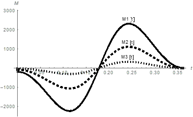
Figure 4 The curves representing controlling torques M1 (N·m), M2 (N·m), and M3 (N·m) as functions of time t (s).
The peak absolute values of controlling torques M1=2321.3 N·m, M2=1115.44 N·m, and M3=326.703 N·m are used for selecting electric motors and reduction gears. The controlling torques M1,M2,M3 are the torques on the output shaft of the reduction gear. It is worth noting, that controlling torques at the hinges corresponding to ankle joint and knee joint became an order of magnitude greater compared to the two-link model. It is related to the addition of body with a mass exceeding the mass of the shin and the mass of the hip taken together.
Using the Figure 4, let’s solve the Cauchy problem for the system of differential equations (2) with controlling torques approximated with step piecewise-specified function. The motion time is broken down into six equal time spans. The controlling torque is assumed to be constant within each time span. The value of controlling torque is calculated as arithmetic mean on the corresponding time span based on the following formula:
Mi,γ=tγ∫tγ−1Mi(t)dttγ−tγ−1, (5)
where i = 1,2,3 is the number of the link controlled by the torque Mi(t),γ – the ranking variable specifying the time span.
The plots in the form of step functions for the controlling torques found in the process of inverse problem solution Figure 4 are presented in the Figure 5, 6
Thus, the inverse dynamics problem for the three-link exoskeleton model has been solved, and the controlling torques have been found. The found controlling torques are used for the Cauchy problem solution.
Solution of the direct problem of dynamics
In the process of the Cauchy problem solution for the system of equations (3), with the controlling torques in the form of step functions shown in the Figure 5, the curves representing the rotation angles, angular velocities, and angular accelerations, presented in the Figure 6, have been obtained.
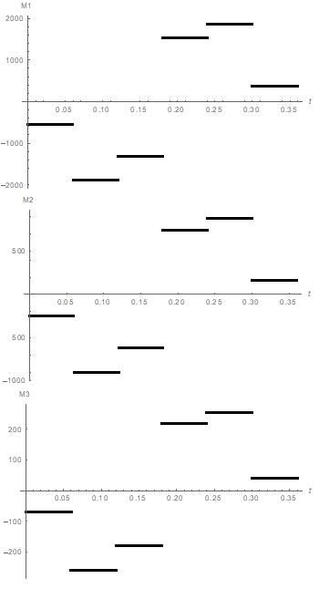
Figure 5 The plots of controlling torques M1 (N·m), M2 (N·m), and M3 (N·m) in the form of piecewise-specified functions of time t (s).
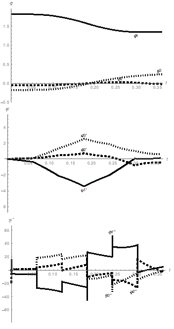
Figure 6 The Cauchy problem solution for three-link mechanism: rotation angles ϕ1,ϕ2,ϕ3 (rad/s2), angular velocities ˙ϕ1,˙ϕ2,˙ϕ3 (rad/s2), and angular accelerations ¨ϕ1,¨ϕ2,¨ϕ3 (rad/s2) of the links as functions of time t (s).
Solving the system of differential equations (2) numerically and comparing the obtained results with the initial motion of the links Figure 2, we can observe good agreement between the link rotation angles and between the angular velocities. The agreement between the angular accelerations is satisfactory. Hence, the impulse control in the form of step functions for the controlling torques Figure 6 is acceptable and can be used to control the link motion.
The energy expenditures during motion of anthropomorphic mechanism with three mobile links are calculated as the work of controlling torques, neglecting resisting forces and energy recuperation during link deceleration:
A=tk∫0(|M1|+|M2|+|M3|)dttk, (6)
where tk – the mechanism motion time, M1,M2,M3 – the controlling torques delivered by mechanism drives.
The following values have been found in the process of calculating the energy expenditures by the drives performing link rotations, provided that controlling torques are specified in the form of step functions Figure 6: Aφ1 = 1251.51 J, Aφ2 = 594.94 J, Aφ3 = 170.07 J. The total energy expenditures for the mechanism amounted to A = 2016.51 J.
A solution tailored to the dynamics of electric drives
As a result of the Cauchy problem solution for the system of differential equations of motion, taking into account the electric drives, and applying the same controlling torques presented in the Figure 5, the curves for the link rotations, presented in the Figure 7, have been obtained.
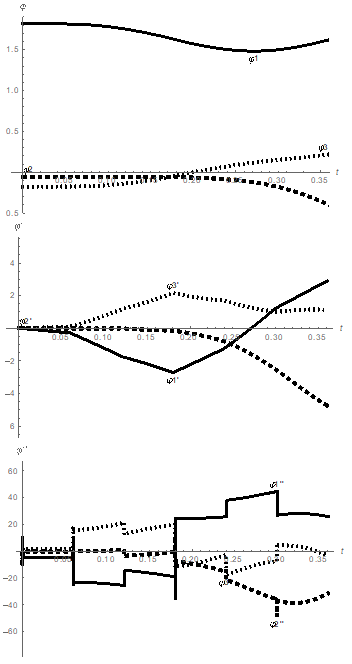
Figure 7 The Cauchy problem solution taking into account the mechanism electric drives: the rotation angles ϕ1,ϕ2,ϕ3 (rad/s2), the angular velocities ˙ϕ1,˙ϕ2,˙ϕ3 (rad/s2), and the angular accelerations ¨ϕ1,¨ϕ2,¨ϕ3 (rad/s2) of the links as functions of time t (s).
Comparing the obtained results with the solution neglecting electric drive impact Figure 6, we can observe poor agreement between link rotation angles, and angular velocities.
The agreement between angular accelerations is satisfactory, especially at the end of the mechanism motion. Therefore, the impact of electric drives on the mechanism dynamics is significant and it should not be neglected in designing models of exoskeletons and anthropomorphic robots. After obtaining poor simulation results based on controlling torques for the model neglecting actual drives, the authors conducted motion simulation with recalculated torques, taking into account the electric drives, and obtained results that are in good agreement. The curves of these results are not listed in the study, because they are very close to the curves presented in the Figure 7. The total energy expenditures for the mechanism amounted to 2030.12 J. The insignificant increase of the energy expenditures by 13.6s1 J, or by 0.68%, with the significant deviation of numerical solution results for the system of differential equations of motion indicate the instability of the derived system. In this case, the stabilization techniques proposed in the papers.13,14 or alternative control methods, considering and compensating disturbances in the model, should be used to improve the simulation results. For example, a neuro-fuzzy control method could be the option.15,16
The electromechanical model of three-link exoskeleton has been created in the study. The simulation of the model dynamics has been conducted in two cases: neglecting the electric drives, and taking them into account. The importance and the necessity of taking electric drives into account for synthesizing controlling torques has been established. The instability of the system of differential equations of motion has been demonstrated. The stabilization techniques should be applied to it during its numerical solution. The proposed exoskeleton model can find practical application in developing actual exoskeletons, anthropomorphic robots, and robotic arms.
The work was supported by the Russian Science Foundation and Smolensk region no. 22-29-20308, https://rscf.ru/en/project/22-29-20308/.
There are no conflicting interests declared by the authors.

©2023 Borisov, et al. This is an open access article distributed under the terms of the, which permits unrestricted use, distribution, and build upon your work non-commercially.