International Journal of
eISSN: 2573-2838


Research Article Volume 4 Issue 3
1Asian Institute of Technology, Thailand
2Department of Physiology, Mahidol University, Thailand
Correspondence: Manukid Parnichkun, Asian Institute of Technology, P.O. Box 4, Klong Luang, Pathumthani 12120, Thailand
Received: March 23, 2018 | Published: May 25, 2018
Citation: Naijit A, Parnichkun M, Pichitpornchai C. Brain-computer-interface based automatic control of robo-rat using a-star. Int J Biosen Bioelectron. 2018;4(3):114–118. DOI: 10.15406/ijbsbe.2018.04.00108
Robots have been applied to the tasks which are not appropriate for human; for examples dangerous, tough, dirty tasks or the tasks which require high accuracy, good repeatability, quick motion. Nowadays, rescue robots are applied to explore unknown areas or even to rescue victims after disasters because of their several superior performances over human. An operator controls every single motion of the rescue robot remotely using information from onboard sensors and cameras. However, in an extreme situation after disaster where the area is messy with many broken objects and obstacles, area exploration and victim rescue are very difficult and time consuming. This situation requires a rescuer who at least can make simple decision and execute the actions. Robo-rat fits very well with this situation. Robo-rat is a rat whose brain is implanted by electrodes and trained to follow commands in the form of brain stimulation using electrical square-wave signals. Three commands are trained to Robo-rat; go straight, turn left and turn right. The electrode at Medial Forebrain Bundle (MFB) is stimulated for go straight command. The electrode at left Somatosensory Cortex is stimulated for turn left command. The electrode at right Somatosensory Cortex is stimulated for turn right command. After manual control of Robo-rat, automatic control is implemented using A-star optimization technique. A camera takes the top view image of the maze. Image processing is conducted to identify Robo-rat position. Based on the map of the maze and the current position, A-star is used to determine the shortest path to the goal position. A PC determines and stimulates electrical pulses at the proper electrodes automatically. The experimental results reveal the feasibility of using Robo-rat for rescue purpose.
Keywords: robo-rat, brain machine interface, a-star
BMI, brain machine interface; SI, somatosensory cortices; MFB, medial forebrain Bundle
Robots have been applied to the tasks which are not appropriate for human; for examples dangerous, tough, dirty tasks or the tasks which require high accuracy, good repeatability, quick motion. Nowadays, rescue robots are applied to explore unknown areas or even to rescue victims after disasters because of their several superior performances over human. Due to flexibility and intelligent limitation of robots, they cannot be applied efficiently in complicated situations; such as search and rescue of survivals in collapsed structures after big disasters. Hence, the concept of animal robot was proposed by scientists and researchers to overcome limitations of the traditional robots. Recently, results of the researches on robo-animals which are controlled by stimulating of certain brain sites are successful. Shimoyama et al.,1 from the University of Tokyo developed a remote-control cockroach.1 Research on Robo-rat was accomplished by Talwar et al.,3 from New York University.2,3 Hirotaka et al.,4 could control the wings and related behaviors of beetles by implanting electrical electrodes on the beetles’ brains and muscles.4 It is widely known that brain machine interface (BMI) has a variety of advantages. There are large number of BMI applications; such as in medical services and in neuroscience researches. Basically, electrodes are used for electrical stimulating by connecting cables between the stimulators and the electrodes that are implanted to animal brain. The tethered stimulation does not only restrict the freedom of animal movement but also distract its attention. In order to solve the problem, tele-stimulation systems was employed to transmit stimulation signal via wireless communication.3 The tele-stimulation system should be small and light to avoid distraction of animal movement. In this paper, the brain computer interface on Robo-rat is proposed.
Rat surgery
A male Sprague-Dawley rat with the weight of 400-500 grams is operated to implant electrodes into three locations of its brains; one electrode at Medial Forebrain Bundle (MFB), two electrodes at left and right Somatosensory cortices (SI). The rat skull at the marked points of MFB and Si are tenderly punctured using handheld screwdriver. In addition, extra holes are punctured for attaching tiny screw poles to support plug body of the three implanted electrodes with dental filler material. After the dental filler material has dried up, the skull with the implanted electrodes are covered up with a suture. The rat with the implanted electrodes is healed up to full health in two weeks after the operation. The rat is then introduced to some exercise programs in order to build up its muscles for walking.
Electrical circuit
Photo and block diagram of the backpack circuit of Robo-rat is shown in Figure 1. The main circuit consists of two parts. The first part is a miniature X-Bee receiver. The receiver is used to receive the stimulation commands from X-Bee transmitter. The second part is a microcontroller module used to receive and translate commands from the X-Bee receiver and generate square-wave signal to stimulate the rat brain at the implanted electrode areas. A miniature X-Bee transmitter connected with a PC is used to deliver the stimulation commands. A converter converts RS232 signal from the PC to TTL 5V signal. This converter uses MAX232 integrated circuit. Besides, an additional simple circuit of a 2-resistor network voltage divider then converts the TTL 5V to 3.3V signal to ensure proper functioning of the X-Bee PRO. Stimulation of rat brain requires routine training programs. The rat without proper training is not able to perform proper actions as per the stimulation commands. Photo and block diagram of PC with the transmitter circuit of Robo-rat is shown in Figure 2. Different voltage levels of brain stimulation create different responses. Too low voltage level cannot stimulate the rat brain. The rat abandons this signal. On the other hand, too high voltage level may harm the rat’s brain tissue and results in several negative effects. In this research, an optimal voltage level is determined by considering from the rat responses after receiving the stimulus. Biphasic stimulation signal is applied to avoid electrolytic injury, compared with a unidirectional stimulation signal. The optimal stimulation signals obtained from the experiments are shown in Table 1.
Stimulation site |
Biphasic stimulus pulses characteristics |
|
||
|---|---|---|---|---|
Pulse duration (ms) |
Number of pulses |
Frequency (Hz) |
Amplitude (V) |
|
MFB |
1 |
8 |
100 |
2.5 |
Left SI cortex |
1 |
5 |
100 |
2.5 |
Right SI cortex |
1 |
5 |
100 |
2.5 |
Table 1 Specifications of each biphasic stimulus pulse
Training program for robo-rat
Stimulation of rat brain requires routine training programs. The rat without proper training is not able to perform proper actions as per the stimulation commands.
MFB stimulation training: MFB stimulation is used for go straight command. The training field of MFB stimulation is a straight track of two-meter length. Firstly, the rat is trained to walk straight in front direction by providing rat foods in front of the rat along with MFB stimulation. Later, the rat foods are removed and only MFB stimulation is conducted. The rat is trained by MFB stimulation for 6 times a day.
Left and right SI stimulations training: Left and right SI stimulations are used for turn left and turn right commands. The training fields of left and right stimulations are junctions. The rat is trained to turn left by providing rat foods to the left of the junction along with left SI stimulation. Later the rat foods are removed and only left SI stimulation is conducted. The rat is trained to turn right by providing rat foods to the right of the junction along with right SI stimulation. Later the rat foods are removed and only right SI stimulation is conducted. The rat is trained by left and right SI stimulations for 5 times each a day.
Complex maze training
A complex maze training field is conducted in order to train and test the performance of the rat in following the commands. The starting point is shown by the green cross sign while the destination point is shown by the red cross sign. The rat has to walk along the assigned route as shown on the ground with blue arrows. The rat is guided by both MFB stimulation and left-right SI stimulations during walking. If the rat heads to correct direction as trained in the earlier training program, the rat will be rewarded with rat foods. The training program completes when the rat completes roaming from the starting point to the destination point following the assigned route. The rat is trained in the complex maze three times a day.
Implementation of A-star algorithm
A-star algorithm is a well-known global-path-planning algorithm for mobile robot, and car navigation system. It combines the advantages of branch-and-bound and under-estimation and dynamic programming optimization algorithms together. It will stop searching for the optimal solution in a branch of the search tree if under-estimated objective function of that branch exceeds the objective function of a known solution. It will also stop searching for the optimal solution in a branch if the objective functions of the intermediate solutions are not minimum. It reduces the dimension of the search tree drastically. A-star algorithm is applied in Robo-rat navigation in this research work. Under-estimated objective function is defined as summation of the accumulated distance with the heuristic distance. When heuristic distance is defined as the straight-line distance from the current rat position to the destination point as shown in Figure 3.
Stimulation voltage level
An experiment is conducted to determine stimulation voltage level under a fixed pulse duration, frequency, and pulse number for Robo-rat. With 1.7 V amplitude of stimulation signal, the rat does not react to the stimulation. With 2.5 V amplitude of stimulation signal, the rat reacts in panic. The rat reacts nicely with the stimulation signal of 2.5 V amplitude at MFB and left and right SI. In the experiments, green, red, and blue visualized LEDs on the backpack circuit represent the left and right SI, and MFB stimulation respectively.
MFB stimulation training
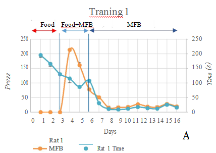
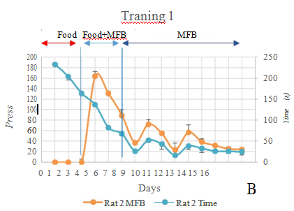
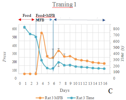
The progress of MFB stimulation training on the rat is shown in Figure 4. On the first two training days, the rat with the backpack does not pay its attention to the rat foods. The rat is excited in its new environment. On the third training day, the rat learns to take the rat foods from the feeding tray. Besides the rat foods, drinking water and milk tablet can be used to allure the rat as well. On the fourth training day, MFB stimulation is displayed by the blue visualized LED. The rat learns to move forward to the front feeding tray to take the rat foods on the fifth training day. On the seventh training day, by only MFB stimulation to the rat brain, the rat learns to move forward. There is no feeding tray in the training field. The rat is rewarded by the feeding tray only after the training.
Left and right SI stimulation training
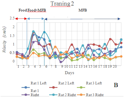
Similar to MFB stimulation training, the rat does not move to take the rat foods in the feeding tray until the third day. On the fourth training day, SI stimulation is provided along with the rat foods in the feeding tray at the desired direction. After the sixth training day, the rat effectively reacts to the SI stimulation by turning its head as guide. The rat still recognizes the MFB stimulation as well. On the thirteenth training day, the rat reacts with higher accuracy than the beginning even without the rat foods. Figure 5 shows the progress of SI stimulation training.

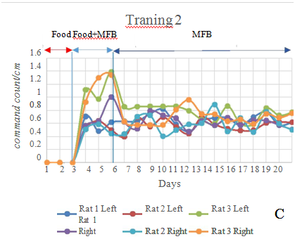
Complex maze training
The rat is tested in 4 patterns of complex maze. Figure 6 shows that the accuracies of the rat in moving correctly in each maze pattern are higher than 80%. Figure 7 shows the performance of 3 rats in all the maze patterns. The rat No.3 has performance lower than the rat No.1 and 2. The results show different performance of different rats even under the same condition. Figure 8 shows photos taken during the experiments of 4 patterns of complex maze.
In this paper, a brain-machine-interface based control of Robo-rat was presented. The wireless communication was applied to enable an operator to remotely guide a roaming rat via laptop or personal computer. The tele stimulator consists of two parts, the backpack system carried by the Robo-rat and the ground station system. Three separate sites of the rat brain; MFB, left and right SI were stimulated through the implanted electrodes. Both MFB stimulation and the left-right-SI stimulation showed that the tele stimulator efficiently guide the rat to the destination point. The Robo-rat performed in the complex maze successfully.
This research was financial supported by Thailand research fund.
Authors declare that there is no conflict of interest.

©2018 Naijit, et al. This is an open access article distributed under the terms of the, which permits unrestricted use, distribution, and build upon your work non-commercially.