Submit manuscript...
eISSN: 2577-8242

Fluid Mechanics Research International Journal

Research Article Volume 2 Issue 1

Ground effect on the aerodynamics of a naca 0015 airfoil with a plain trailing-edge flap

V Tremblay Dionne, T Lee

Department of Mechanical Engineering, McGill University, Canada

Correspondence: T Lee, Department of Mechanical Engineering, McGill University 817 Sherbrooke St West, Montreal, Quebec, H3A 2K6, Canada

Received: August 31, 2017 | Published: January 25, 2018

Citation: Dionne VT, Lee T (2018) Ground Effect on the Aerodynamics of A NACA 0015 Airfoil with A Plain Trailing-Edge Flap. Fluid Mech Res Int 2(1): 00015. DOI: 10.15406/fmrij.2018.02.00015

Download PDF

Abstract

The ground effect on the aerodynamics of a NACA 0015 airfoil with a plain trailing-edge flap was investigated experimentally at Re=1.61´105. The ground proximity led to an increased lift and nose-down pitching moment compared to their out-of-the-ground effect counterparts. The flap deployment also caused the flow separation to move further upstream, rendering to an earlier stall as the ground was approached. The amount of lift increment was, however, found to be most significant at low angles of attack and was reduced with increasing trailing-edge flap deflection. Meanwhile, the pressure drag of the flapped airfoil was reduced in ground effect. The enhanced aerodynamics of the flapped airfoil, especially in close ground proximity can greatly benefit the take-off and landing of WIG (wing-in-ground effect) craft.

Keywords: wing-in-ground effect (wig) craft, experimental aerodynamics and fluid mechanics, trailing-edge flap, low-speed aerodynamics

Abbreviations

c, chord; u MathType@MTEF@5@5@+= feaagKart1ev2aaatCvAUfeBSjuyZL2yd9gzLbvyNv2CaerbuLwBLn hiov2DGi1BTfMBaeXatLxBI9gBaerbd9wDYLwzYbItLDharqqtubsr 4rNCHbGeaGqkY=gjVeeu0dXdPqFfpec8Eeeu0xXdbba9frFj0=OqFf ea0dXdd9vqaq=JfrVkFHe9pgea0dXdar=Jb9hs0dXdbPYxe9vr0=vr 0=vqpWqaaeaabiGaciaacaqabeaadaqaaqaaaOqaaabaaaaaaaaape GaamyDamaaBaaaleaacqGHEisPaeqaaaaa@38FD@ , free stream velocity; n, kinematic viscosity; Re, chord reynolds number, (= u c/n) MathType@MTEF@5@5@+= feaagKart1ev2aaatCvAUfeBSjuyZL2yd9gzLbvyNv2CaerbuLwBLn hiov2DGi1BTfMBaeXatLxBI9gBaerbd9wDYLwzYbItLDharqqtubsr 4rNCHbGeaGqkY=gjVeeu0dXdPqFfpec8Eeeu0xXdbba9frFj0=OqFf ea0dXdd9vqaq=JfrVkFHe9pgea0dXdar=Jb9hs0dXdbPYxe9vr0=vr 0=vqpWqaaeaabiGaciaacaqabeaadaqaaqaaaOqaaiaacIcaqaaaaa aaaaWdbiabg2da9iaadwhapaWaaSbaaSqaa8qacqGHEisPa8aabeaa k8qacaWGJbGaai4laiaad6gapaGaaiykaaaa@3E41@ ; OGE, out of the ground effect; GE, ground effect; Cd, sectional drag coefficient; Cdp, sectional pressure drag coefficient; Cl, sectional lift coefficient; Cl,max, maximum Cl; C l α MathType@MTEF@5@5@+= feaagKart1ev2aaatCvAUfeBSjuyZL2yd9gzLbvyNv2CaerbuLwBLn hiov2DGi1BTfMBaeXatLxBI9gBaerbd9wDYLwzYbItLDharqqtubsr 4rNCHbGeaGqkY=gjVeeu0dXdPqFfpec8Eeeu0xXdbba9frFj0=OqFf ea0dXdd9vqaq=JfrVkFHe9pgea0dXdar=Jb9hs0dXdbPYxe9vr0=vr 0=vqpWqaaeaabiGaciaacaqabeaadaqaaqaaaOqaaabaaaaaaaaape Gaam4qa8aadaWgaaWcbaWdbiaadYgaa8aabeaakmaaBaaaleaapeGa eqySdegapaqabaaaaa@3A6D@ ,lift-curve slope; Cm, sectional pitching moment coefficient; Cm,peak, peak Cm, value; p MathType@MTEF@5@5@+= feaagKart1ev2aaatCvAUfeBSjuyZL2yd9gzLbvyNv2CaerbuLwBLn hiov2DGi1BTfMBaeXatLxBI9gBaerbd9wDYLwzYbItLDharqqtubsr 4rNCHbGeaGqkY=gjVeeu0dXdPqFfpec8Eeeu0xXdbba9frFj0=OqFf ea0dXdd9vqaq=JfrVkFHe9pgea0dXdar=Jb9hs0dXdbPYxe9vr0=vr 0=vqpWqaaeaabiGaciaacaqabeaadaqaaqaaaOqaaabaaaaaaaaape GaamiCa8aadaWgaaWcbaWdbiabg6HiLcWdaeqaaaaa@3926@ , freestream pressure; Cp, surface pressure coefficient, (=(p   p )/½ρ u 2 ) MathType@MTEF@5@5@+= feaagKart1ev2aaatCvAUfeBSjuyZL2yd9gzLbvyNv2CaerbuLwBLn hiov2DGi1BTfMBaeXatLxBI9gBaerbd9wDYLwzYbItLDharqqtubsr 4rNCHbGeaGqkY=gjVeeu0dXdPqFfpec8Eeeu0xXdbba9frFj0=OqFf ea0dXdd9vqaq=JfrVkFHe9pgea0dXdar=Jb9hs0dXdbPYxe9vr0=vr 0=vqpWqaaeaabiGaciaacaqabeaadaqaaqaaaOqaaiaacIcaqaaaaa aaaaWdbiabg2da98aacaGGOaWdbiaadchacaqGGaGaeyOeI0Iaaeii aiaadchapaWaaSbaaSqaa8qacqGHEisPa8aabeaakiaacMcapeGaai 4laiaac2lacqaHbpGCcaWG1bWdamaaBaaaleaapeGaeyOhIukapaqa baGcdaahaaWcbeqaa8qacaaIYaaaaOWdaiaacMcaaaa@47D4@ ; TEF. trailing-edge Flap; h, distance between airfoil trailing edge and ground; h MathType@MTEF@5@5@+= feaagKart1ev2aaatCvAUfeBSjuyZL2yd9gzLbvyNv2CaerbuLwBLn hiov2DGi1BTfMBaeXatLxBI9gBaerbd9wDYLwzYbItLDharqqtubsr 4rNCHbGeaGqkY=gjVeeu0dXdPqFfpec8Eeeu0xXdbba9frFj0=OqFf ea0dXdd9vqaq=JfrVkFHe9pgea0dXdar=Jb9hs0dXdbPYxe9vr0=vr 0=vqpWqaaeaabiGaciaacaqabeaadaqaaqaaaOqaaabaaaaaaaaape GabmiAayaafaaaaa@375F@ , distance between flapped TEF and ground; δ TE MathType@MTEF@5@5@+= feaagKart1ev2aaatCvAUfeBSjuyZL2yd9gzLbvyNv2CaerbuLwBLn hiov2DGi1BTfMBaeXatLxBI9gBaerbd9wDYLwzYbItLDharqqtubsr 4rNCHbGeaGqkY=gjVeeu0dXdPqFfpec8Eeeu0xXdbba9frFj0=OqFf ea0dXdd9vqaq=JfrVkFHe9pgea0dXdar=Jb9hs0dXdbPYxe9vr0=vr 0=vqpWqaaeaabiGaciaacaqabeaadaqaaqaaaOqaaabaaaaaaaaape GaeqiTdq2damaaBaaaleaapeGaamivaiaadweaa8aabeaaaaa@3A08@ , trailing-edge flap deflection angle; α MathType@MTEF@5@5@+= feaagKart1ev2aaatCvAUfeBSjuyZL2yd9gzLbvyNv2CaerbuLwBLn hiov2DGi1BTfMBaeXatLxBI9gBaerbd9wDYLwzYbItLDharqqtubsr 4rNCHbGeaGqkY=gjVeeu0dXdPqFfpec8Eeeu0xXdbba9frFj0=OqFf ea0dXdd9vqaq=JfrVkFHe9pgea0dXdar=Jb9hs0dXdbPYxe9vr0=vr 0=vqpWqaaeaabiGaciaacaqabeaadaqaaqaaaOqaaiabeg7aHbaa@37E5@ , angle of attack; α ss MathType@MTEF@5@5@+= feaagKart1ev2aaatCvAUfeBSjuyZL2yd9gzLbvyNv2CaerbuLwBLn hiov2DGi1BTfMBaeXatLxBI9gBaerbd9wDYLwzYbItLDharqqtubsr 4rNCHbGeaGqkY=gjVeeu0dXdPqFfpec8Eeeu0xXdbba9frFj0=OqFf ea0dXdd9vqaq=JfrVkFHe9pgea0dXdar=Jb9hs0dXdbPYxe9vr0=vr 0=vqpWqaaeaabiGaciaacaqabeaadaqaaqaaaOqaaiabeg7aHnaaBa aaleaacaWGZbGaam4Caaqabaaaaa@3A01@ , static-stall angle

Introduction

It is known that for aircraft flying in close ground proximity, for example, during landing and takeoff, can generate a considerable lift augmentation and lift-induced drag reduction and, more importantly, a greatly enhanced lift-to-drag ratio as compared to aircraft flying out of the ground effect. The ground effect-induced lift augmentation can be attributed to the dynamic air cushion phenomenon or the so-called RAM pressure created between the wing’s lower surface and the ground, while the lift-induced drag reduction is caused by the suppression of downwash angle and strength as well as to the increased effective aspect ratio in ground effect. The resulting high lift-to-drag ratio of the WIG (wing-in-ground effect) craft thus lead to an increased flight range with a lower specific fuel consumption, and has therefore attracted considerable attention in potential civil and military applications. The Russian Ekranoplan-type WIG craft, with large square wings and a small aspect ratio, were particularly designed and constructed to utilize the above-mentioned beneficial ground effect. To overcome the poor longitudinal stability, a large horizontal stabilizer mounted high and operated out of the ground effect is, however, required by the Ekranoplan WIG craft. Additionally, the power augmented ram (PAR) wings and large trailing-edge flaps were also employed to overcome the “hump drag” during the take-off. The PAR wing concept directs the exhaust air from the engines under the main wings to generate more lift, but greatly complicates the WIG craft system. Extensive investigations have been conducted to quantify the stability1‒3 and aerodynamics4‒12 of rectangular NACA wings, of various airfoil profiles, in ground effect. A most recent study of the ground effect on the aerodynamics of a NACA 0012 airfoil, both stationary and unsteady, was given by Lee et al.12 An in-depth review on the Ekranoplan-type WIG craft was given by Rozhdestvensky.13 In this study, only the research work related to trailing-edge flaps in ground effect was discussed.

The trailing-edge flap has been employed extensively to alter camber in the trailing-edge region and to adjust longitudinal stability, as well as to augment the lift, especially during landing and takeoff. Only limited archived research publications have, however, been devoted to rectangular wings or airfoils in ground effect.14,15 Note that the aerodynamic characteristics of inverted front wings, with or without trailing-edge flaps, of Formula One race cars in ground effect have been investigated by the research group at the University of Southampton.16,17 It was found that the downforce increased asymmetrically with a reduction in height and that the maximum downforce was dictated by gains in downforce from lower-surface suction increases and losses in downforce caused by upper-surface pressure. Also, for large flap angles there was a sharp reduction just beyond the maximum, mainly because of the boundary layer separating, and a resultant loss of circulation on the main element.

Steinbach & Jacob14 studied the flaps and slats both numerically and experimentally on the wing’s aerodynamics and found that wing systems with excessive flap-slat mechanization were often unfavorable in the distant ground effect as the wing effective camber produced a negative ground effect. They also showed that as a high-lift airfoil with a flap approached the ground, the flap efficiency decreased and the separation point moved further upstream. As the airfoil further approached the ground, the flap was shown to provide improved aerodynamic properties. Unlike the lift, the drag was shown to be significantly higher for the out of ground case, while reducing in ground proximity. Overall, the lift and drag increased with the angle of attack α MathType@MTEF@5@5@+= feaagKart1ev2aaatCvAUfeBSjuyZL2yd9gzLbvyNv2CaerbuLwBLn hiov2DGi1BTfMBaeXatLxBI9gBaerbd9wDYLwzYbItLDharqqtubsr 4rNCHbGeaGqkY=gjVeeu0dXdPqFfpec8Eeeu0xXdbba9frFj0=OqFf ea0dXdd9vqaq=JfrVkFHe9pgea0dXdar=Jb9hs0dXdbPYxe9vr0=vr 0=vqpWqaaeaabiGaciaacaqabeaadaqaaqaaaOqaaiabeg7aHbaa@37E5@ , while in some regions the use of flap in weak ground effect yielded a smaller lift than in the out of ground case. Meanwhile, the pressure was found to drop slightly near the leading edge of the airfoil, while rose near the trailing edge which thereby caused flow separation at a low α MathType@MTEF@5@5@+= feaagKart1ev2aaatCvAUfeBSjuyZL2yd9gzLbvyNv2CaerbuLwBLn hiov2DGi1BTfMBaeXatLxBI9gBaerbd9wDYLwzYbItLDharqqtubsr 4rNCHbGeaGqkY=gjVeeu0dXdPqFfpec8Eeeu0xXdbba9frFj0=OqFf ea0dXdd9vqaq=JfrVkFHe9pgea0dXdar=Jb9hs0dXdbPYxe9vr0=vr 0=vqpWqaaeaabiGaciaacaqabeaadaqaaqaaaOqaaiabeg7aHbaa@37E5@ than for an airfoil in a free stream.

Ockfen & Matveev15 investigated experimentally the ground proximity (for h/c=5% to 15%) on the aerodynamic properties of a NACA 4412 with a plain trailing-edge flap (TEF) at α= 2 o MathType@MTEF@5@5@+= feaagKart1ev2aaatCvAUfeBSjuyZL2yd9gzLbvyNv2CaerbuLwBLn hiov2DGi1BTfMBaeXatLxBI9gBaerbd9wDYLwzYbItLDharqqtubsr 4rNCHbGeaGqkY=gjVeeu0dXdPqFfpec8Eeeu0xXdbba9frFj0=OqFf ea0dXdd9vqaq=JfrVkFHe9pgea0dXdar=Jb9hs0dXdbPYxe9vr0=vr 0=vqpWqaaeaabiGaciaacaqabeaadaqaaqaaaOqaaabaaaaaaaaape GaeqySdeMaeyypa0JaaGOma8aadaahaaWcbeqaa8qacaWGVbaaaaaa @3B07@ and 6 o MathType@MTEF@5@5@+= feaagKart1ev2aaatCvAUfeBSjuyZL2yd9gzLbvyNv2CaerbuLwBLn hiov2DGi1BTfMBaeXatLxBI9gBaerbd9wDYLwzYbItLDharqqtubsr 4rNCHbGeaGqkY=gjVeeu0dXdPqFfpec8Eeeu0xXdbba9frFj0=OqFf ea0dXdd9vqaq=JfrVkFHe9pgea0dXdar=Jb9hs0dXdbPYxe9vr0=vr 0=vqpWqaaeaabiGaciaacaqabeaadaqaaqaaaOqaaiaaiAdadaahaa WcbeqaaabaaaaaaaaapeGaam4Baaaaaaa@3847@ for Re=106. They observed that the TEF deflection increased the amount of flow trapped underneath the airfoil, leading to a considerable slowdown of the flow speed in this region and subsequently a large pressure recovery beneath the airfoil. The amount of lift augmentation due to the flap, however, appeared to lessen as the flap deflection was increased. Therefore, deflecting the flap in extreme ground effect was very effective with small deflections, while the benefit of further deflecting the flap yielded a diminishing gain. They further oberved that the drag coefficient was also increased with flap deflection, as a result of the pressure drag produced by the TEF deflection-caused increased area perpendicular to the flow coupled with the RAM pressure. Additionally, the nose-down pitching moment was also found to increase with reducing ground clearance, as a consequence of the larger pressure beneath the airfoil acting agaisnt the increased area of the blunt flap. Finally, the lift-to-drag ratio was also improved in ground effect, which is one of the selling points of WIG craft.

In summary, the deployment of a plain trailing-edge flap, especially in extreme ground effect region, is known to be the most beneficial aerodynamic properties for WIG craft. However, only limited published investigations, covering for h/c=5 to 15% at limited α MathType@MTEF@5@5@+= feaagKart1ev2aaatCvAUfeBSjuyZL2yd9gzLbvyNv2CaerbuLwBLn hiov2DGi1BTfMBaeXatLxBI9gBaerbd9wDYLwzYbItLDharqqtubsr 4rNCHbGeaGqkY=gjVeeu0dXdPqFfpec8Eeeu0xXdbba9frFj0=OqFf ea0dXdd9vqaq=JfrVkFHe9pgea0dXdar=Jb9hs0dXdbPYxe9vr0=vr 0=vqpWqaaeaabiGaciaacaqabeaadaqaaqaaaOqaaiabeg7aHbaa@37E5@ , have been conducted by researchers elsewhere. There is still a great need for a more extensive measurement covering a wide range of ground clearance (i.e., between 0% and 60%) and α MathType@MTEF@5@5@+= feaagKart1ev2aaatCvAUfeBSjuyZL2yd9gzLbvyNv2CaerbuLwBLn hiov2DGi1BTfMBaeXatLxBI9gBaerbd9wDYLwzYbItLDharqqtubsr 4rNCHbGeaGqkY=gjVeeu0dXdPqFfpec8Eeeu0xXdbba9frFj0=OqFf ea0dXdd9vqaq=JfrVkFHe9pgea0dXdar=Jb9hs0dXdbPYxe9vr0=vr 0=vqpWqaaeaabiGaciaacaqabeaadaqaaqaaaOqaaiabeg7aHbaa@37E5@ . The objective of this study was therefore aimed at quantifying the aerodynamics of a NACA 0015 airfoil, equipped with a 25%c plain trailing-edge flap, for 0%≤h/c≤60% at α= 2 o to  16 o MathType@MTEF@5@5@+= feaagKart1ev2aaatCvAUfeBSjuyZL2yd9gzLbvyNv2CaerbuLwBLn hiov2DGi1BTfMBaeXatLxBI9gBaerbd9wDYLwzYbItLDharqqtubsr 4rNCHbGeaGqkY=gjVeeu0dXdPqFfpec8Eeeu0xXdbba9frFj0=OqFf ea0dXdd9vqaq=JfrVkFHe9pgea0dXdar=Jb9hs0dXdbPYxe9vr0=vr 0=vqpWqaaeaabiGaciaacaqabeaadaqaaqaaaOqaaabaaaaaaaaape GaeqySdeMaeyypa0JaaGOma8aadaahaaWcbeqaa8qacaWGVbaaaOGa amiDaiaad+gacaqGGaGaaGymaiaaiAdapaWaaWbaaSqabeaapeGaam 4Baaaaaaa@405C@ through surface pressure measurements. Aerodynamic properties of both the flapped and unflapped airfoils operating out of ground effect were also obtained to serve as a comparison.

Materials and Methods

The experiment was conducted in the 0.9m ´ 1.2m ´ 2.7m suction-type wind tunnel at McGill University at Re=1.61´105. A rectangular NC-machined aluminum NACA 0015 airfoil with a chord c=25.4cm and a span b=37.5cm was used as the test model. The airfoil model was also equipped with a plain trailing-edge flap of a length of 25%c. The origin of the coordinates was located at the leading edge of the airfoil. The airfoil was pitched at 1/4-chord location. The wing model was mounted between two vertical Plexiglas walls. A moveable Plexiglas plate with a 25-deg sharp leading edge was used to simulate the ground effect.12 The schematic of the airfoil model and the definition of the ground clearance are given in Figure 1a. The fixed ground method was adopted based on its simplicity. To simulate the actual flow conditions encountered when a WIG wing flies close the ground, the moving wall method, e.g., the moving-belt method employed by Ahmed et al.8 should be considered.
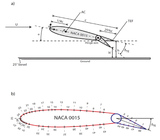
Figure 1 (a) Schematic of the airfoil model and definitions of trailing-edge flap deflection δTE and ground clearance ( h and  h ) MathType@MTEF@5@5@+= feaagKart1ev2aaatCvAUfeBSjuyZL2yd9gzLbvyNv2CaerbuLwBLn hiov2DGi1BTfMBaeXatLxBI9gBaerbd9wDYLwzYbItLDharqqtubsr 4rNCHbGeaGqkY=gjVeeu0dXdPqFfpec8Eeeu0xXdbba9frFj0=OqFf ea0dXdd9vqaq=JfrVkFHe9pgea0dXdar=Jb9hs0dXdbPYxe9vr0=vr 0=vqpWqaaeaabiGaciaacaqabeaadaqaaqaaaOqaamaabmaabaaeaa aaaaaaa8qacaWGObGaaeiiaiaadggacaWGUbGaamizaiaabccaceWG ObGbauaaa8aacaGLOaGaayzkaaaaaa@3DEC@ , and (b) pressure orifice locations.

The airfoil model was also equipped with 48 0.35-mm-diameter pressure orifices, distributed both along the upper and bottom surfaces of the airfoil (Figure 1b), which were connected to a 48-port Scanivalve system in conjunction with an YQCH-250-1 pressure transducer via 22-cm long and 0.75-mm i.d. plastic tubings. The location of the pressure orifices is given in Table 1. The aerodynamic load coefficients were obtained through the integration of the surface pressure distributions. The uncertainty of the surface pressure coefficient Cp measurements was estimated to be ±0.013 MathType@MTEF@5@5@+= feaagKart1ev2aaatCvAUfeBSjuyZL2yd9gzLbvyNv2CaerbuLwBLn hiov2DGi1BTfMBaeXatLxBI9gBaerbd9wDYLwzYbItLDharqqtubsr 4rNCHbGeaGqkY=gjVeeu0dXdPqFfpec8Eeeu0xXdbba9frFj0=OqFf ea0dXdd9vqaq=JfrVkFHe9pgea0dXdar=Jb9hs0dXdbPYxe9vr0=vr 0=vqpWqaaeaabiGaciaacaqabeaadaqaaqaaaOqaaabaaaaaaaaape GaeyySaeRaaGimaiaac6cacaaIWaGaaGymaiaaiodaaaa@3BF2@ .

#

x/c

y/c

Angle ( ) MathType@MTEF@5@5@+= feaagKart1ev2aaatCvAUfeBSjuyZL2yd9gzLbvyNv2CaerbuLwBLn hiov2DGi1BTfMBaeXatLxBI9gBaerbd9wDYLwzYbItLDharqqtubsr 4rNCHbGeaGqkY=gjVeeu0dXdPqFfpec8Eeeu0xXdbba9frFj0=OqFf ea0dXdd9vqaq=JfrVkFHe9pgea0dXdar=Jb9hs0dXdbPYxe9vr0=vr 0=vqpWqaaeaabiGaciaacaqabeaadaqaaqaaaOqaaabaaaaaaaaape GaaiikamaaCaaaleqabaqcLbsacqWIyiYBaaGccaGGPaaaaa@39BF@

1

0.9626

0.008

80.49

25

0

0

180

2

0.9013

0.0179

81.14

26

0.0015

-0.0084

-160.31

3

0.86

0.0242

81.55

27

0.0071

-0.0181

-140.66

4

0.825

0.0293

81.88

28

0.0152

-0.0259

-128.73

5

0.7957

0.0334

82.16

29

0.0255

-0.033

-120.55

6

0.6523

0.0514

83.55

30

0.0358

-0.0384

-115.46

7

0.6238

0.0545

83.86

31

0.0483

-0.0438

-111.2

8

0.5698

0.06

84.51

32

0.071

-0.0514

-106.12

9

0.5197

0.0646

85.19

33

0.1462

-0.0663

-97.53

10

0.4703

0.0684

85.97

34

0.1781

-0.0699

-95.36

11

0.4209

0.0715

86.89

35

0.2207

-0.073

-93.09

12

0.3712

0.0737

87.99

36

0.272

-0.0748

-90.96

13

0.3205

0.0749

89.36

37

0.3454

-0.0745

-88.65

14

0.2724

0.0748

90.95

38

0.4205

-0.0715

-86.9

15

0.2476

0.0742

91.9

39

0.4684

-0.0685

-86.01

16

0.2219

0.0731

93.04

40

0.5185

-0.0647

-85.21

17

0.1787

0.07

95.33

41

0.569

-0.0601

-84.52

18

0.1505

0.0669

97.22

42

0.6237

-0.0546

-83.86

19

0.1176

0.0619

100.01

43

0.6525

-0.0514

-83.55

20

0.0915

0.0567

102.97

44

0.7958

-0.0334

-82.16

21

0.0732

0.052

105.74

45

0.8251

-0.0293

-81.88

22

0.049

0.0441

111

46

0.8623

-0.0238

-81.53

23

0.0278

0.0343

119.22

47

0.9025

-0.0177

-81.13

24

0.0057

0.0163

143.98

48

0.9599

-0.0084

-80.52

Table 1 NACA 0015 orifice locations (before TEF deflection)

Result and Discussion

Before the discussion of the flapped NACA 0015 airfoil (i.e., with trailing-edge flap deflection) in ground effect, the aerodynamics of the unflapped airfoil is discussed first.

Unflapped airfoil in ground effect

Figure 2(a) shows the variation of Cl of the unflapped NACA 0015 airfoil with h/c (=0% to 60%) at α= 2 o to  16 o MathType@MTEF@5@5@+= feaagKart1ev2aaatCvAUfeBSjuyZL2yd9gzLbvyNv2CaerbuLwBLn hiov2DGi1BTfMBaeXatLxBI9gBaerbd9wDYLwzYbItLDharqqtubsr 4rNCHbGeaGqkY=gjVeeu0dXdPqFfpec8Eeeu0xXdbba9frFj0=OqFf ea0dXdd9vqaq=JfrVkFHe9pgea0dXdar=Jb9hs0dXdbPYxe9vr0=vr 0=vqpWqaaeaabiGaciaacaqabeaadaqaaqaaaOqaaabaaaaaaaaape GaeqySdeMaeyypa0JaaGOma8aadaahaaWcbeqaa8qacaWGVbaaaOGa amiDaiaad+gacaqGGaGaaGymaiaaiAdapaWaaWbaaSqabeaapeGaam 4Baaaaaaa@405C@ . The baseline airfoil (i.e., in a free stream or operating out of the ground effect), with a static-stall angle α ss MathType@MTEF@5@5@+= feaagKart1ev2aaatCvAUfeBSjuyZL2yd9gzLbvyNv2CaerbuLwBLn hiov2DGi1BTfMBaeXatLxBI9gBaerbd9wDYLwzYbItLDharqqtubsr 4rNCHbGeaGqkY=gjVeeu0dXdPqFfpec8Eeeu0xXdbba9frFj0=OqFf ea0dXdd9vqaq=JfrVkFHe9pgea0dXdar=Jb9hs0dXdbPYxe9vr0=vr 0=vqpWqaaeaabiGaciaacaqabeaadaqaaqaaaOqaaabaaaaaaaaape GaeqySde2damaaBaaaleaapeGaam4Caiaadohaa8aabeaaaaa@3A4F@  of 15o and a Cl,max of 1.09, was also included in this figure for a direct comparison. In ground effect, there was an increase in the lift-curve slope C lα MathType@MTEF@5@5@+= feaagKart1ev2aaatCvAUfeBSjuyZL2yd9gzLbvyNv2CaerbuLwBLn hiov2DGi1BTfMBaeXatLxBI9gBaerbd9wDYLwzYbItLDharqqtubsr 4rNCHbGeaGqkY=gjVeeu0dXdPqFfpec8Eeeu0xXdbba9frFj0=OqFf ea0dXdd9vqaq=JfrVkFHe9pgea0dXdar=Jb9hs0dXdbPYxe9vr0=vr 0=vqpWqaaeaabiGaciaacaqabeaadaqaaqaaaOqaaabaaaaaaaaape Gaam4qa8aadaWgaaWcbaqcLbmapeGaamiBaiabeg7aHbWcpaqabaaa aa@3B51@  compared to the baseline airfoil. The smaller the h/c the larger the C lα MathType@MTEF@5@5@+= feaagKart1ev2aaatCvAUfeBSjuyZL2yd9gzLbvyNv2CaerbuLwBLn hiov2DGi1BTfMBaeXatLxBI9gBaerbd9wDYLwzYbItLDharqqtubsr 4rNCHbGeaGqkY=gjVeeu0dXdPqFfpec8Eeeu0xXdbba9frFj0=OqFf ea0dXdd9vqaq=JfrVkFHe9pgea0dXdar=Jb9hs0dXdbPYxe9vr0=vr 0=vqpWqaaeaabiGaciaacaqabeaadaqaaqaaaOqaaabaaaaaaaaape Gaam4qa8aadaWgaaWcbaWdbiaadYgacqaHXoqya8aabeaaaaa@3A18@ became. The Cl, however, had a negative value for α   3 o MathType@MTEF@5@5@+= feaagKart1ev2aaatCvAUfeBSjuyZL2yd9gzLbvyNv2CaerbuLwBLn hiov2DGi1BTfMBaeXatLxBI9gBaerbd9wDYLwzYbItLDharqqtubsr 4rNCHbGeaGqkY=gjVeeu0dXdPqFfpec8Eeeu0xXdbba9frFj0=OqFf ea0dXdd9vqaq=JfrVkFHe9pgea0dXdar=Jb9hs0dXdbPYxe9vr0=vr 0=vqpWqaaeaabiGaciaacaqabeaadaqaaqaaaOqaaabaaaaaaaaape GaeqySdeMaaeiiaiabgsMiJkaabccacaaIZaWdamaaCaaaleqabaWd biaad+gaaaaaaa@3CFD@ , due to the Venturi or converging-diverging flow passage developed underneath the NACA 0015 airfoil and the ensuing suction pressure build-up on the airfoil’s lower surface (see the blue line in Figure 2b). Also, the smaller the h/c the more negative the Cl became. For 3 o <α   α ss MathType@MTEF@5@5@+= feaagKart1ev2aaatCvAUfeBSjuyZL2yd9gzLbvyNv2CaerbuLwBLn hiov2DGi1BTfMBaeXatLxBI9gBaerbd9wDYLwzYbItLDharqqtubsr 4rNCHbGeaGqkY=gjVeeu0dXdPqFfpec8Eeeu0xXdbba9frFj0=OqFf ea0dXdd9vqaq=JfrVkFHe9pgea0dXdar=Jb9hs0dXdbPYxe9vr0=vr 0=vqpWqaaeaabiGaciaacaqabeaadaqaaqaaaOqaaabaaaaaaaaape GaaG4ma8aadaahaaWcbeqaa8qacaWGVbaaaOGaeyipaWJaeqySdeMa aeiiaiabgsMiJkaabccacqaHXoqypaWaaSbaaSqaa8qacaWGZbGaam 4CaaWdaeqaaaaa@41F4@ , the Cl value was found to increase above the out-of-the-ground effect value, mainly due to the RAM pressure acted on the airfoil’s lower surface (see, for example, at α= 10 o MathType@MTEF@5@5@+= feaagKart1ev2aaatCvAUfeBSjuyZL2yd9gzLbvyNv2CaerbuLwBLn hiov2DGi1BTfMBaeXatLxBI9gBaerbd9wDYLwzYbItLDharqqtubsr 4rNCHbGeaGqkY=gjVeeu0dXdPqFfpec8Eeeu0xXdbba9frFj0=OqFf ea0dXdd9vqaq=JfrVkFHe9pgea0dXdar=Jb9hs0dXdbPYxe9vr0=vr 0=vqpWqaaeaabiGaciaacaqabeaadaqaaqaaaOqaaabaaaaaaaaape GaeqySdeMaeyypa0JaaGymaiaaicdapaWaaWbaaSqabeaapeGaam4B aaaaaaa@3BC0@ in Figure 2b). The smaller the h/c the higher the RAM pressure or lift was achieved. Note that for h/c³60%, the change in Cl became marginal.
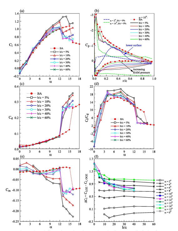
Figure 2 Ground effect of aerodynamic properties and surface pressure distribution of unflapped NACA 0015 airfoil. BA denotes base line airfoil in a free stream.

The Cp measurements further indicate that the suction pressure, including the suction peak, developed on the airfoil’s upper surface was lower than the baseline-airfoil value for all α (< α ss ) MathType@MTEF@5@5@+= feaagKart1ev2aaatCvAUfeBSjuyZL2yd9gzLbvyNv2CaerbuLwBLn hiov2DGi1BTfMBaeXatLxBI9gBaerbd9wDYLwzYbItLDharqqtubsr 4rNCHbGeaGqkY=gjVeeu0dXdPqFfpec8Eeeu0xXdbba9frFj0=OqFf ea0dXdd9vqaq=JfrVkFHe9pgea0dXdar=Jb9hs0dXdbPYxe9vr0=vr 0=vqpWqaaeaabiGaciaacaqabeaadaqaaqaaaOqaaabaaaaaaaaape GaeqySdeMaaeiia8aacaGGOaWdbiabgYda8iabeg7aH9aadaWgaaWc baWdbiaadohacaWGZbaapaqabaGccaGGPaaaaa@3F17@ and h/c tested in the present study. There was also a loss of suction pressure increase near the trailing edge of the NACA 0015 airfoil’s upper surface as the ground was approached, suggesting an increased adverse dp/dx and, subsequently, an earlier flow separation compared to the baseline airfoil (Figure 2b). The smaller the h/c the earlier the stall for h/c£60% tested. For h/c=5%, the α ss MathType@MTEF@5@5@+= feaagKart1ev2aaatCvAUfeBSjuyZL2yd9gzLbvyNv2CaerbuLwBLn hiov2DGi1BTfMBaeXatLxBI9gBaerbd9wDYLwzYbItLDharqqtubsr 4rNCHbGeaGqkY=gjVeeu0dXdPqFfpec8Eeeu0xXdbba9frFj0=OqFf ea0dXdd9vqaq=JfrVkFHe9pgea0dXdar=Jb9hs0dXdbPYxe9vr0=vr 0=vqpWqaaeaabiGaciaacaqabeaadaqaaqaaaOqaaabaaaaaaaaape GaeqySde2damaaBaaaleaapeGaam4Caiaadohaa8aabeaaaaa@3A4F@ remained basically unchanged. The change in the suction pressure on the airfoil’s upper surface was also found to be insensitive to h/c for α> 3 o MathType@MTEF@5@5@+= feaagKart1ev2aaatCvAUfeBSjuyZL2yd9gzLbvyNv2CaerbuLwBLn hiov2DGi1BTfMBaeXatLxBI9gBaerbd9wDYLwzYbItLDharqqtubsr 4rNCHbGeaGqkY=gjVeeu0dXdPqFfpec8Eeeu0xXdbba9frFj0=OqFf ea0dXdd9vqaq=JfrVkFHe9pgea0dXdar=Jb9hs0dXdbPYxe9vr0=vr 0=vqpWqaaeaabiGaciaacaqabeaadaqaaqaaaOqaaabaaaaaaaaape GaeqySdeMaeyOpa4JaaG4ma8aadaahaaWcbeqaa8qacaWGVbaaaaaa @3B0A@ .

Figure 2c shows that the Cd was also found to be a weak function of h/c; i.e., the Cd remained close to the baseline-airfoil value for a<ass in ground effect. The Cl augmentation thus led to an improved Cl/Cd in ground effect for α   α ss MathType@MTEF@5@5@+= feaagKart1ev2aaatCvAUfeBSjuyZL2yd9gzLbvyNv2CaerbuLwBLn hiov2DGi1BTfMBaeXatLxBI9gBaerbd9wDYLwzYbItLDharqqtubsr 4rNCHbGeaGqkY=gjVeeu0dXdPqFfpec8Eeeu0xXdbba9frFj0=OqFf ea0dXdd9vqaq=JfrVkFHe9pgea0dXdar=Jb9hs0dXdbPYxe9vr0=vr 0=vqpWqaaeaabiGaciaacaqabeaadaqaaqaaaOqaaabaaaaaaaaape GaeqySdeMaaeiiaiabgsMiJkaabccacqaHXoqypaWaaSbaaSqaa8qa caWGZbGaam4CaaWdaeqaaOGaaGPaVdaa@407E@  (Figure 2d). There, however, exhibited a considerable increase in nose-down Cm in the medium-to-high α MathType@MTEF@5@5@+= feaagKart1ev2aaatCvAUfeBSjuyZL2yd9gzLbvyNv2CaerbuLwBLn hiov2DGi1BTfMBaeXatLxBI9gBaerbd9wDYLwzYbItLDharqqtubsr 4rNCHbGeaGqkY=gjVeeu0dXdPqFfpec8Eeeu0xXdbba9frFj0=OqFf ea0dXdd9vqaq=JfrVkFHe9pgea0dXdar=Jb9hs0dXdbPYxe9vr0=vr 0=vqpWqaaeaabiGaciaacaqabeaadaqaaqaaaOqaaabaaaaaaaaape GaeqySdegaaa@3805@  regime as the ground was approached (Figure 2e); a major drawback of WIG craft. To better quantify the impactful ground effect on the lift production, the increment Cl (i.e., Δ C l = C l ,GE C l ,OGE MathType@MTEF@5@5@+= feaagKart1ev2aaatCvAUfeBSjuyZL2yd9gzLbvyNv2CaerbuLwBLn hiov2DGi1BTfMBaeXatLxBI9gBaerbd9wDYLwzYbItLDharqqtubsr 4rNCHbGeaGqkY=gjVeeu0dXdPqFfpec8Eeeu0xXdbba9frFj0=OqFf ea0dXdd9vqaq=JfrVkFHe9pgea0dXdar=Jb9hs0dXdbPYxe9vr0=vr 0=vqpWqaaeaabiGaciaacaqabeaadaqaaqaaaOqaaabaaaaaaaaape GaeuiLdqKaam4qa8aadaWgaaWcbaWdbiaadYgaa8aabeaak8qacqGH 9aqpcaWGdbWdamaaBaaaleaapeGaamiBaaWdaeqaaOWaaSbaaSqaa8 qacaGGSaGaam4raiaadweaa8aabeaak8qacqGHsislcaWGdbWdamaa BaaaleaapeGaamiBaaWdaeqaaOWaaSbaaSqaa8qacaGGSaGaam4tai aadEeacaWGfbaapaqabaaaaa@4636@ , where GE and OGE denote ground effect and out of the ground effect, respectively) as a function of h/c at each α MathType@MTEF@5@5@+= feaagKart1ev2aaatCvAUfeBSjuyZL2yd9gzLbvyNv2CaerbuLwBLn hiov2DGi1BTfMBaeXatLxBI9gBaerbd9wDYLwzYbItLDharqqtubsr 4rNCHbGeaGqkY=gjVeeu0dXdPqFfpec8Eeeu0xXdbba9frFj0=OqFf ea0dXdd9vqaq=JfrVkFHe9pgea0dXdar=Jb9hs0dXdbPYxe9vr0=vr 0=vqpWqaaeaabiGaciaacaqabeaadaqaaqaaaOqaaabaaaaaaaaape GaeqySdegaaa@3805@  is also presented in Figure 2f. As can be seen, the ground proximity had a greater impact on Cl of the unflapped airfoil at higher α MathType@MTEF@5@5@+= feaagKart1ev2aaatCvAUfeBSjuyZL2yd9gzLbvyNv2CaerbuLwBLn hiov2DGi1BTfMBaeXatLxBI9gBaerbd9wDYLwzYbItLDharqqtubsr 4rNCHbGeaGqkY=gjVeeu0dXdPqFfpec8Eeeu0xXdbba9frFj0=OqFf ea0dXdd9vqaq=JfrVkFHe9pgea0dXdar=Jb9hs0dXdbPYxe9vr0=vr 0=vqpWqaaeaabiGaciaacaqabeaadaqaaqaaaOqaaabaaaaaaaaape GaeqySdegaaa@3805@ . Also, the smaller the h/c the larger Cl increment was obtained. The ground effect, however, became less impactful for h/c>10%.

Airfoil with TEF deflection

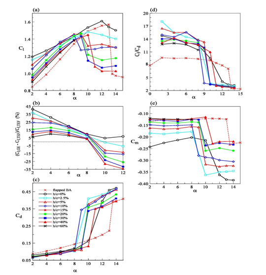
TEF out of ground effect: Figure 3(a) summarizes the overall Cl behavior of the flapped NACA 0015 airfoil with δ TE = 5 o to  23 o MathType@MTEF@5@5@+= feaagKart1ev2aaatCvAUfeBSjuyZL2yd9gzLbvyNv2CaerbuLwBLn hiov2DGi1BTfMBaeXatLxBI9gBaerbd9wDYLwzYbItLDharqqtubsr 4rNCHbGeaGqkY=gjVeeu0dXdPqFfpec8Eeeu0xXdbba9frFj0=OqFf ea0dXdd9vqaq=JfrVkFHe9pgea0dXdar=Jb9hs0dXdbPYxe9vr0=vr 0=vqpWqaaeaabiGaciaacaqabeaadaqaaqaaaOqaaabaaaaaaaaape GaeqiTdq2damaaBaaaleaapeGaamivaiaadweaa8aabeaak8qacqGH 9aqpcaaI1aWdamaaCaaaleqabaWdbiaad+gaaaGccaWG0bGaam4Bai aabccacaaIYaGaaG4ma8aadaahaaWcbeqaa8qacaWGVbaaaaaa@427A@ in a free stream. The TEF deployment, in comparison with the unflapped airfoil, led to

    1. Leftward shift of the C l α MathType@MTEF@5@5@+= feaagKart1ev2aaatCvAUfeBSjuyZL2yd9gzLbvyNv2CaerbuLwBLn hiov2DGi1BTfMBaeXatLxBI9gBaerbd9wDYLwzYbItLDharqqtubsr 4rNCHbGeaGqkY=gjVeeu0dXdPqFfpec8Eeeu0xXdbba9frFj0=OqFf ea0dXdd9vqaq=JfrVkFHe9pgea0dXdar=Jb9hs0dXdbPYxe9vr0=vr 0=vqpWqaaeaabiGaciaacaqabeaadaqaaqaaaOqaaabaaaaaaaaape Gaam4qa8aadaWgaaWcbaWdbiaadYgaa8aabeaak8qacqGHsislcqaH Xoqyaaa@3B1F@  curve accompanied by a non-zero C l at α= 0 o MathType@MTEF@5@5@+= feaagKart1ev2aaatCvAUfeBSjuyZL2yd9gzLbvyNv2CaerbuLwBLn hiov2DGi1BTfMBaeXatLxBI9gBaerbd9wDYLwzYbItLDharqqtubsr 4rNCHbGeaGqkY=gjVeeu0dXdPqFfpec8Eeeu0xXdbba9frFj0=OqFf ea0dXdd9vqaq=JfrVkFHe9pgea0dXdar=Jb9hs0dXdbPYxe9vr0=vr 0=vqpWqaaeaabiGaciaacaqabeaadaqaaqaaaOqaaabaaaaaaaaape Gaam4qa8aadaWgaaWcbaWdbiaadYgaa8aabeaakiaaykW7peGaamyy aiaadshacaqGGaGaeqySdeMaeyypa0JaaGima8aadaahaaWcbeqaa8 qacaWGVbaaaaaa@413F@ ;
    2. A large Cl enhancement caused by the pressure increase along the airfoil (Figure 3b) and the TEF-induced positive camber;
    3. A suction pressure increase (especially in the flap region), including its peak value; and
    4. A promoted stall and the earlier stall, originating from the boundary-layer flow separation and the flap-caused obstruction of the stream wise flow, also resulted in a large pressure drag increase compared to the unflapped airfoil in a free stream (Figure 3c).
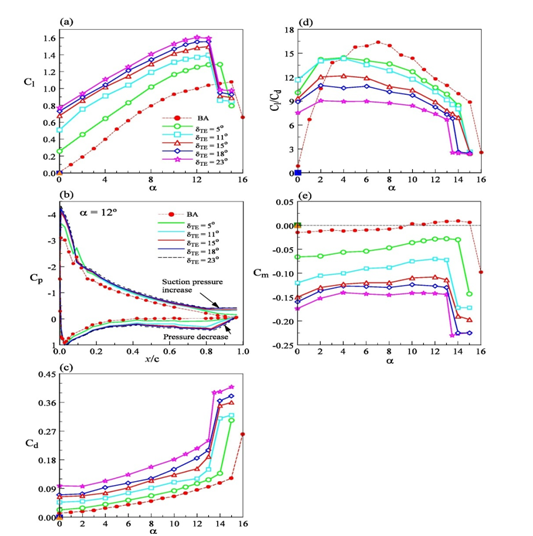
Figure 3 Aerodynamic behavior and Cp flapped airfoil in a free stream.

The pressure underneath the airfoil increased with increasing δ TE MathType@MTEF@5@5@+= feaagKart1ev2aaatCvAUfeBSjuyZL2yd9gzLbvyNv2CaerbuLwBLn hiov2DGi1BTfMBaeXatLxBI9gBaerbd9wDYLwzYbItLDharqqtubsr 4rNCHbGeaGqkY=gjVeeu0dXdPqFfpec8Eeeu0xXdbba9frFj0=OqFf ea0dXdd9vqaq=JfrVkFHe9pgea0dXdar=Jb9hs0dXdbPYxe9vr0=vr 0=vqpWqaaeaabiGaciaacaqabeaadaqaaqaaaOqaaabaaaaaaaaape GaeqiTdq2damaaBaaaleaapeGaamivaiaadweaa8aabeaaaaa@3A08@ . The large Cd increase overwhelmed the corresponding Cl increase, rendering a lowered Cl/Cd ratio (Figure 3d) compared to its unflapped counterpart. The TEF deflection also generated a substantial nose-down Cm (Figure 3e), attributing to the large pressure increase exerted on the lower side of the flap. The higher the δ TE MathType@MTEF@5@5@+= feaagKart1ev2aaatCvAUfeBSjuyZL2yd9gzLbvyNv2CaerbuLwBLn hiov2DGi1BTfMBaeXatLxBI9gBaerbd9wDYLwzYbItLDharqqtubsr 4rNCHbGeaGqkY=gjVeeu0dXdPqFfpec8Eeeu0xXdbba9frFj0=OqFf ea0dXdd9vqaq=JfrVkFHe9pgea0dXdar=Jb9hs0dXdbPYxe9vr0=vr 0=vqpWqaaeaabiGaciaacaqabeaadaqaaqaaaOqaaabaaaaaaaaape GaeqiTdq2damaaBaaaleaapeGaamivaiaadweaa8aabeaaaaa@3A08@ the larger the nose-down Cm, Cl and Cd became.

In the next section, the ground clearance (h¢/c = 0% to 60%) on the flapped NACA 0015 airfoil with different δ TE MathType@MTEF@5@5@+= feaagKart1ev2aaatCvAUfeBSjuyZL2yd9gzLbvyNv2CaerbuLwBLn hiov2DGi1BTfMBaeXatLxBI9gBaerbd9wDYLwzYbItLDharqqtubsr 4rNCHbGeaGqkY=gjVeeu0dXdPqFfpec8Eeeu0xXdbba9frFj0=OqFf ea0dXdd9vqaq=JfrVkFHe9pgea0dXdar=Jb9hs0dXdbPYxe9vr0=vr 0=vqpWqaaeaabiGaciaacaqabeaadaqaaqaaaOqaaabaaaaaaaaape GaeqiTdq2damaaBaaaleaapeGaamivaiaadweaa8aabeaaaaa@3A08@  is discussed. h¢ is the distance between the trailing edge of the deflected flap and the ground as specified in Figure 1a. Special attention was placed on the immediate vicinity of the ground surface with h¢/c £ 5%, which corresponds to the main-wing TEF deployment of the Russian KM WIG craft to create a static air cushion below during takeoff by almost closing off the trailing edge against the ground plane.

TEF in ground effect: In contrast to the flapped airfoil in a free stream, the presence of the ground caused

    1. A further increase in Cl for all h¢/c tested;
    2. The flap deflection was most effective in the low-α range;
    3. The relative amount of lift increment appeared to lessen as the flap deflection δ TE MathType@MTEF@5@5@+= feaagKart1ev2aaatCvAUfeBSjuyZL2yd9gzLbvyNv2CaerbuLwBLn hiov2DGi1BTfMBaeXatLxBI9gBaerbd9wDYLwzYbItLDharqqtubsr 4rNCHbGeaGqkY=gjVeeu0dXdPqFfpec8Eeeu0xXdbba9frFj0=OqFf ea0dXdd9vqaq=JfrVkFHe9pgea0dXdar=Jb9hs0dXdbPYxe9vr0=vr 0=vqpWqaaeaabiGaciaacaqabeaadaqaaqaaaOqaaabaaaaaaaaape GaeqiTdq2damaaBaaaleaapeGaamivaiaadweaa8aabeaaaaa@3A08@ was increased (i.e., the impact of ground proximity decreased as the flap deflection was increased);
    4. A lowered Cd decreased with reducing h¢/c;
    5. The Cl/Cd ratio and the nose-down Cm increased as h¢/c was decreased; and
    6. A stronger adverse dp/dx which together with the jet-type flow through the diminishing gap at the trailing edge led to an earlier flow separation and subsequently a promoted stall. To illustrate the ground proximity on the above-mentioned observations, the aerodynamic properties and the Cp distributions for the δ TE = 23 o MathType@MTEF@5@5@+= feaagKart1ev2aaatCvAUfeBSjuyZL2yd9gzLbvyNv2CaerbuLwBLn hiov2DGi1BTfMBaeXatLxBI9gBaerbd9wDYLwzYbItLDharqqtubsr 4rNCHbGeaGqkY=gjVeeu0dXdPqFfpec8Eeeu0xXdbba9frFj0=OqFf ea0dXdd9vqaq=JfrVkFHe9pgea0dXdar=Jb9hs0dXdbPYxe9vr0=vr 0=vqpWqaaeaabiGaciaacaqabeaadaqaaqaaaOqaaabaaaaaaaaape GaeqiTdq2damaaBaaaleaapeGaamivaiaadweaa8aabeaak8qacqGH 9aqpcaaIYaGaaG4ma8aadaahaaWcbeqaa8qacaWGVbaaaaaa@3DE1@ flap deflection were discussed first, followed by the δ TE = 5 o MathType@MTEF@5@5@+= feaagKart1ev2aaatCvAUfeBSjuyZL2yd9gzLbvyNv2CaerbuLwBLn hiov2DGi1BTfMBaeXatLxBI9gBaerbd9wDYLwzYbItLDharqqtubsr 4rNCHbGeaGqkY=gjVeeu0dXdPqFfpec8Eeeu0xXdbba9frFj0=OqFf ea0dXdd9vqaq=JfrVkFHe9pgea0dXdar=Jb9hs0dXdbPYxe9vr0=vr 0=vqpWqaaeaabiGaciaacaqabeaadaqaaqaaaOqaaabaaaaaaaaape GaeqiTdq2damaaBaaaleaapeGaamivaiaadweaa8aabeaak8qacqGH 9aqpcaaI1aWdamaaCaaaleqabaWdbiaad+gaaaaaaa@3D27@  deflection.

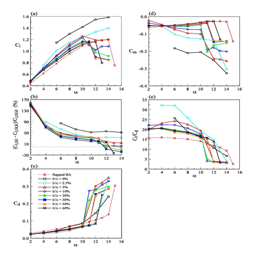
Figure 4a demonstrates that for δ TE = 23 o MathType@MTEF@5@5@+= feaagKart1ev2aaatCvAUfeBSjuyZL2yd9gzLbvyNv2CaerbuLwBLn hiov2DGi1BTfMBaeXatLxBI9gBaerbd9wDYLwzYbItLDharqqtubsr 4rNCHbGeaGqkY=gjVeeu0dXdPqFfpec8Eeeu0xXdbba9frFj0=OqFf ea0dXdd9vqaq=JfrVkFHe9pgea0dXdar=Jb9hs0dXdbPYxe9vr0=vr 0=vqpWqaaeaabiGaciaacaqabeaadaqaaqaaaOqaaabaaaaaaaaape GaeqiTdq2damaaBaaaleaapeGaamivaiaadweaa8aabeaak8qacqGH 9aqpcaaIYaGaaG4ma8aadaahaaWcbeqaa8qacaWGVbaaaaaa@3DE1@ deflection the Cl was increased with reducing h¢/c (up to α ss MathType@MTEF@5@5@+= feaagKart1ev2aaatCvAUfeBSjuyZL2yd9gzLbvyNv2CaerbuLwBLn hiov2DGi1BTfMBaeXatLxBI9gBaerbd9wDYLwzYbItLDharqqtubsr 4rNCHbGeaGqkY=gjVeeu0dXdPqFfpec8Eeeu0xXdbba9frFj0=OqFf ea0dXdd9vqaq=JfrVkFHe9pgea0dXdar=Jb9hs0dXdbPYxe9vr0=vr 0=vqpWqaaeaabiGaciaacaqabeaadaqaaqaaaOqaaabaaaaaaaaape GaeqySde2damaaBaaaleaapeGaam4Caiaadohaa8aabeaaaaa@3A4F@ ) compared to its out-of-the-ground effect counterpart, as a result of the increased amount of flow slowed down and/or trapped underneath the flapped airfoil and the subsequent RAM pressure increase (see, for example at α= 8 o MathType@MTEF@5@5@+= feaagKart1ev2aaatCvAUfeBSjuyZL2yd9gzLbvyNv2CaerbuLwBLn hiov2DGi1BTfMBaeXatLxBI9gBaerbd9wDYLwzYbItLDharqqtubsr 4rNCHbGeaGqkY=gjVeeu0dXdPqFfpec8Eeeu0xXdbba9frFj0=OqFf ea0dXdd9vqaq=JfrVkFHe9pgea0dXdar=Jb9hs0dXdbPYxe9vr0=vr 0=vqpWqaaeaabiGaciaacaqabeaadaqaaqaaaOqaaabaaaaaaaaape GaeqySdeMaeyypa0JaaGioa8aadaahaaWcbeqaa8qacaWGVbaaaaaa @3B0D@ and 10o presented in (Figure 5a & Figure 5b). At a fixed δ TE MathType@MTEF@5@5@+= feaagKart1ev2aaatCvAUfeBSjuyZL2yd9gzLbvyNv2CaerbuLwBLn hiov2DGi1BTfMBaeXatLxBI9gBaerbd9wDYLwzYbItLDharqqtubsr 4rNCHbGeaGqkY=gjVeeu0dXdPqFfpec8Eeeu0xXdbba9frFj0=OqFf ea0dXdd9vqaq=JfrVkFHe9pgea0dXdar=Jb9hs0dXdbPYxe9vr0=vr 0=vqpWqaaeaabiGaciaacaqabeaadaqaaqaaaOqaaabaaaaaaaaape GaeqiTdq2damaaBaaaleaapeGaamivaiaadweaa8aabeaaaaa@3A08@ , the ground proximity on the flapped airfoil was most beneficial at low α MathType@MTEF@5@5@+= feaagKart1ev2aaatCvAUfeBSjuyZL2yd9gzLbvyNv2CaerbuLwBLn hiov2DGi1BTfMBaeXatLxBI9gBaerbd9wDYLwzYbItLDharqqtubsr 4rNCHbGeaGqkY=gjVeeu0dXdPqFfpec8Eeeu0xXdbba9frFj0=OqFf ea0dXdd9vqaq=JfrVkFHe9pgea0dXdar=Jb9hs0dXdbPYxe9vr0=vr 0=vqpWqaaeaabiGaciaacaqabeaadaqaaqaaaOqaaabaaaaaaaaape GaeqySdegaaa@3805@  (Figure 4b); i.e., the observed relative Cl increment decreased rapidly as α MathType@MTEF@5@5@+= feaagKart1ev2aaatCvAUfeBSjuyZL2yd9gzLbvyNv2CaerbuLwBLn hiov2DGi1BTfMBaeXatLxBI9gBaerbd9wDYLwzYbItLDharqqtubsr 4rNCHbGeaGqkY=gjVeeu0dXdPqFfpec8Eeeu0xXdbba9frFj0=OqFf ea0dXdd9vqaq=JfrVkFHe9pgea0dXdar=Jb9hs0dXdbPYxe9vr0=vr 0=vqpWqaaeaabiGaciaacaqabeaadaqaaqaaaOqaaabaaaaaaaaape GaeqySdegaaa@3805@ was increased. Figure 4b also indicates that at a fixed α(forα< α ss ) MathType@MTEF@5@5@+= feaagKart1ev2aaatCvAUfeBSjuyZL2yd9gzLbvyNv2CaerbuLwBLn hiov2DGi1BTfMBaeXatLxBI9gBaerbd9wDYLwzYbItLDharqqtubsr 4rNCHbGeaGqkY=gjVeeu0dXdPqFfpec8Eeeu0xXdbba9frFj0=OqFf ea0dXdd9vqaq=JfrVkFHe9pgea0dXdar=Jb9hs0dXdbPYxe9vr0=vr 0=vqpWqaaeaabiGaciaacaqabeaadaqaaqaaaOqaaabaaaaaaaaape GaeqySde2daiaacIcapeGaamOzaiaad+gacaWGYbGaaGPaVlaaykW7 cqaHXoqycqGH8aapcqaHXoqypaWaaSbaaSqaa8qacaWGZbGaam4Caa WdaeqaaOGaaiykaaaa@45FF@ the Cl increment decreased significantly with increasing h¢/c and that the largest Cl increment occurred in extreme ground proximity (i.e., h¢/c£10%) and became much less significant for h¢/c>20%. For at the limiting h¢/c=0% case, the ass remained virtually unchanged compared to the flapped airfoil in a free stream. For h¢/c³5%, the flapped airfoil stalled was observed to stall before α= 9 o MathType@MTEF@5@5@+= feaagKart1ev2aaatCvAUfeBSjuyZL2yd9gzLbvyNv2CaerbuLwBLn hiov2DGi1BTfMBaeXatLxBI9gBaerbd9wDYLwzYbItLDharqqtubsr 4rNCHbGeaGqkY=gjVeeu0dXdPqFfpec8Eeeu0xXdbba9frFj0=OqFf ea0dXdd9vqaq=JfrVkFHe9pgea0dXdar=Jb9hs0dXdbPYxe9vr0=vr 0=vqpWqaaeaabiGaciaacaqabeaadaqaaqaaaOqaaabaaaaaaaaape GaeqySdeMaeyypa0JaaGyoa8aadaahaaWcbeqaa8qacaWGVbaaaaaa @3B0E@ .

Figure 4 Ground effect on the flapped airfoil with δ TE = 23 MathType@MTEF@5@5@+= feaagKart1ev2aaatCvAUfeBSjuyZL2yd9gzLbvyNv2CaerbuLwBLn hiov2DGi1BTfMBaeXatLxBI9gBaerbd9wDYLwzYbItLDharqqtubsr 4rNCHbGeaGqkY=gjVeeu0dXdPqFfpec8Eeeu0xXdbba9frFj0=OqFf ea0dXdd9vqaq=JfrVkFHe9pgea0dXdar=Jb9hs0dXdbPYxe9vr0=vr 0=vqpWqaaeaabiGaciaacaqabeaadaqaaqaaaOqaaiabes7aKnaaBa aaleaacaWGubGaamyraaqabaGccqGH9aqpcaaIYaGaaG4mamaaCaaa leqabaGaeSigI8gaaaaa@3DAA@ . C1,GE and C1,OGE denote C1 of the deflected airfoil in GE and OGE respectively.

Figures 5a to 5b further reveal that the ground proximity also gave an increased suction peak but a lower suction pressure along the flapped airfoil’s upper surface. The smaller the h’/c the large the RAM pressure and suction peak were achieved. The increased RAM pressure forced a larger amount of flow over the nose of the airfoil producing an accelerated flow over the flapped airfoil’s upper surface rendering an increased suction peak. The accelerated flow however confronted an ever-increasing dp/dx as it traveled downstream leading to an earlier stall. The increased dp/dx>0 gradient can be reflected from the suction pressure decrease on the upper surface of the flapped airfoil (e.g., at α= 8 o MathType@MTEF@5@5@+= feaagKart1ev2aaatCvAUfeBSjuyZL2yd9gzLbvyNv2CaerbuLwBLn hiov2DGi1BTfMBaeXatLxBI9gBaerbd9wDYLwzYbItLDharqqtubsr 4rNCHbGeaGqkY=gjVeeu0dXdPqFfpec8Eeeu0xXdbba9frFj0=OqFf ea0dXdd9vqaq=JfrVkFHe9pgea0dXdar=Jb9hs0dXdbPYxe9vr0=vr 0=vqpWqaaeaabiGaciaacaqabeaadaqaaqaaaOqaaiaaykW7qaaaaa aaaaWdbiabeg7aHjabg2da9iaaiIdapaWaaWbaaSqabeaapeGaam4B aaaaaaa@3C98@ in Figure 5a). Figure 5b that the Cp had an almost constant +1.0 value on the airfoil’s lower surface (denoted by the black line) for the limiting h¢/c=0% condition, and that the flapped airfoil reached an earlier for h/c>10% as demonstrated by the flat Cp distribution along the airfoil’s upper surface.
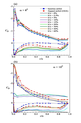
Figure 5 Surface pressure coefficient of the flapped airfoil with δ TE = 23 MathType@MTEF@5@5@+= feaagKart1ev2aaatCvAUfeBSjuyZL2yd9gzLbvyNv2CaerbuLwBLn hiov2DGi1BTfMBaeXatLxBI9gBaerbd9wDYLwzYbItLDharqqtubsr 4rNCHbGeaGqkY=gjVeeu0dXdPqFfpec8Eeeu0xXdbba9frFj0=OqFf ea0dXdd9vqaq=JfrVkFHe9pgea0dXdar=Jb9hs0dXdbPYxe9vr0=vr 0=vqpWqaaeaabiGaciaacaqabeaadaqaaqaaaOqaaiabes7aKnaaBa aaleaacaWGubGaamyraaqabaGccqGH9aqpcaaIYaGaaG4mamaaCaaa leqabaGaeSigI8gaaaaa@3DAA@  in the ground effect.

Figure 4c reveals that in ground effect there was a reduction in Cd of the flapped airfoil compared to the no-ground effect value for α   α ss MathType@MTEF@5@5@+= feaagKart1ev2aaatCvAUfeBSjuyZL2yd9gzLbvyNv2CaerbuLwBLn hiov2DGi1BTfMBaeXatLxBI9gBaerbd9wDYLwzYbItLDharqqtubsr 4rNCHbGeaGqkY=gjVeeu0dXdPqFfpec8Eeeu0xXdbba9frFj0=OqFf ea0dXdd9vqaq=JfrVkFHe9pgea0dXdar=Jb9hs0dXdbPYxe9vr0=vr 0=vqpWqaaeaabiGaciaacaqabeaadaqaaqaaaOqaaabaaaaaaaaape GaeqySdeMaaeiiaiabgsMiJkaabccacqaHXoqypaWaaSbaaSqaa8qa caWGZbGaam4CaaWdaeqaaaaa@3EE9@ , which can be attributed to the ground effect-induced flow acceleration in the leading-edge region of the flapped airfoil which allowed the flow to remain further attached for α   α ss MathType@MTEF@5@5@+= feaagKart1ev2aaatCvAUfeBSjuyZL2yd9gzLbvyNv2CaerbuLwBLn hiov2DGi1BTfMBaeXatLxBI9gBaerbd9wDYLwzYbItLDharqqtubsr 4rNCHbGeaGqkY=gjVeeu0dXdPqFfpec8Eeeu0xXdbba9frFj0=OqFf ea0dXdd9vqaq=JfrVkFHe9pgea0dXdar=Jb9hs0dXdbPYxe9vr0=vr 0=vqpWqaaeaabiGaciaacaqabeaadaqaaqaaaOqaaabaaaaaaaaape GaeqySdeMaaeiiaiabgsMiJkaabccacqaHXoqypaWaaSbaaSqaa8qa caWGZbGaam4CaaWdaeqaaaaa@3EE9@ . The Cd reduction, however, appeared to be insensitive to h¢/c. The Cl increase and Cd reduction of the flapped airfoil in ground effect always produced an increased Cl/Cd ratio for α   α ss MathType@MTEF@5@5@+= feaagKart1ev2aaatCvAUfeBSjuyZL2yd9gzLbvyNv2CaerbuLwBLn hiov2DGi1BTfMBaeXatLxBI9gBaerbd9wDYLwzYbItLDharqqtubsr 4rNCHbGeaGqkY=gjVeeu0dXdPqFfpec8Eeeu0xXdbba9frFj0=OqFf ea0dXdd9vqaq=JfrVkFHe9pgea0dXdar=Jb9hs0dXdbPYxe9vr0=vr 0=vqpWqaaeaabiGaciaacaqabeaadaqaaqaaaOqaaabaaaaaaaaape GaeqySdeMaaeiiaiabgsMiJkaabccacqaHXoqypaWaaSbaaSqaa8qa caWGZbGaam4CaaWdaeqaaaaa@3EE9@  (Figure 4d). Despite of the favorable impact on Cl, Cd and Cl/Cd, the ground proximity also led to a further increase in the nose-down Cm (Figure 4e), which can further deteriorate the pitch stability of the flapped airfoil.

Now, the ground effect on the flapped airfoil with δ TE =5 o MathType@MTEF@5@5@+= feaagKart1ev2aaatCvAUfeBSjuyZL2yd9gzLbvyNv2CaerbuLwBLn hiov2DGi1BTfMBaeXatLxBI9gBaerbd9wDYLwzYbItLDharqqtubsr 4rNCHbGeaGqkY=gjVeeu0dXdPqFfpec8Eeeu0xXdbba9frFj0=OqFf ea0dXdd9vqaq=JfrVkFHe9pgea0dXdar=Jb9hs0dXdbPYxe9vr0=vr 0=vqpWqaaeaabiGaciaacaqabeaadaqaaqaaaOqaaabaaaaaaaaape GaaeiTd8aadaWgaaWcbaWdbiaabsfacaqGfbaapaqabaGcpeGaaeyp aiaabwdapaWaaWbaaSqabeaapeGaae4Baaaaaaa@3C69@ is illustrated in Figure 6. Similar to the δ TE =5 o MathType@MTEF@5@5@+= feaagKart1ev2aaatCvAUfeBSjuyZL2yd9gzLbvyNv2CaerbuLwBLn hiov2DGi1BTfMBaeXatLxBI9gBaerbd9wDYLwzYbItLDharqqtubsr 4rNCHbGeaGqkY=gjVeeu0dXdPqFfpec8Eeeu0xXdbba9frFj0=OqFf ea0dXdd9vqaq=JfrVkFHe9pgea0dXdar=Jb9hs0dXdbPYxe9vr0=vr 0=vqpWqaaeaabiGaciaacaqabeaadaqaaqaaaOqaaabaaaaaaaaape GaaeiTd8aadaWgaaWcbaWdbiaabsfacaqGfbaapaqabaGcpeGaaeyp aiaabwdapaWaaWbaaSqabeaapeGaae4Baaaaaaa@3C69@  deflection, the Cl increased sharply with reducing h¢/c, especially for h¢/c<10% (Figure 6a). A 90% increase in Cl for h¢/c=2.5%, for example, at α=4 o MathType@MTEF@5@5@+= feaagKart1ev2aaatCvAUfeBSjuyZL2yd9gzLbvyNv2CaerbuLwBLn hiov2DGi1BTfMBaeXatLxBI9gBaerbd9wDYLwzYbItLDharqqtubsr 4rNCHbGeaGqkY=gjVeeu0dXdPqFfpec8Eeeu0xXdbba9frFj0=OqFf ea0dXdd9vqaq=JfrVkFHe9pgea0dXdar=Jb9hs0dXdbPYxe9vr0=vr 0=vqpWqaaeaabiGaciaacaqabeaadaqaaqaaaOqaaabaaaaaaaaape GaaeySdiaab2dacaqG0aWdamaaCaaaleqabaWdbiaab+gaaaaaaa@3A52@  was obtained (Figure 6b) in comparison with 26% of its δ TE =23 o MathType@MTEF@5@5@+= feaagKart1ev2aaatCvAUfeBSjuyZL2yd9gzLbvyNv2CaerbuLwBLn hiov2DGi1BTfMBaeXatLxBI9gBaerbd9wDYLwzYbItLDharqqtubsr 4rNCHbGeaGqkY=gjVeeu0dXdPqFfpec8Eeeu0xXdbba9frFj0=OqFf ea0dXdd9vqaq=JfrVkFHe9pgea0dXdar=Jb9hs0dXdbPYxe9vr0=vr 0=vqpWqaaeaabiGaciaacaqabeaadaqaaqaaaOqaaabaaaaaaaaape GaaeiTd8aadaWgaaWcbaWdbiaabsfacaqGfbaapaqabaGcpeGaaeyp aiaabkdacaqGZaWdamaaCaaaleqabaWdbiaab+gaaaaaaa@3D1C@  counterparts. The Cd, Cl/Cd and Cm were also found to increase in ground effect (Figure 6c to 6d). The extent of Cl enhancement of the δ TE =5 o MathType@MTEF@5@5@+= feaagKart1ev2aaatCvAUfeBSjuyZL2yd9gzLbvyNv2CaerbuLwBLn hiov2DGi1BTfMBaeXatLxBI9gBaerbd9wDYLwzYbItLDharqqtubsr 4rNCHbGeaGqkY=gjVeeu0dXdPqFfpec8Eeeu0xXdbba9frFj0=OqFf ea0dXdd9vqaq=JfrVkFHe9pgea0dXdar=Jb9hs0dXdbPYxe9vr0=vr 0=vqpWqaaeaabiGaciaacaqabeaadaqaaqaaaOqaaabaaaaaaaaape GaaeiTd8aadaWgaaWcbaWdbiaabsfacaqGfbaapaqabaGcpeGaaeyp aiaabwdapaWaaWbaaSqabeaapeGaae4Baaaaaaa@3C69@  flap deflection was, however, of a much greater extent as compared to the δ TE =23 o MathType@MTEF@5@5@+= feaagKart1ev2aaatCvAUfeBSjuyZL2yd9gzLbvyNv2CaerbuLwBLn hiov2DGi1BTfMBaeXatLxBI9gBaerbd9wDYLwzYbItLDharqqtubsr 4rNCHbGeaGqkY=gjVeeu0dXdPqFfpec8Eeeu0xXdbba9frFj0=OqFf ea0dXdd9vqaq=JfrVkFHe9pgea0dXdar=Jb9hs0dXdbPYxe9vr0=vr 0=vqpWqaaeaabiGaciaacaqabeaadaqaaqaaaOqaaabaaaaaaaaape GaaeiTd8aadaWgaaWcbaWdbiaabsfacaqGfbaapaqabaGcpeGaaeyp aiaabkdacaqGZaWdamaaCaaaleqabaWdbiaab+gaaaaaaa@3D1C@ case.

Figure 6 Ground effect on the flapped NACA 0015 airfoil with δ TE = 5 MathType@MTEF@5@5@+= feaagKart1ev2aaatCvAUfeBSjuyZL2yd9gzLbvyNv2CaerbuLwBLn hiov2DGi1BTfMBaeXatLxBI9gBaerbd9wDYLwzYbItLDharqqtubsr 4rNCHbGeaGqkY=gjVeeu0dXdPqFfpec8Eeeu0xXdbba9frFj0=OqFf ea0dXdd9vqaq=JfrVkFHe9pgea0dXdar=Jb9hs0dXdbPYxe9vr0=vr 0=vqpWqaaeaabiGaciaacaqabeaadaqaaqaaaOqaaiabes7aKnaaBa aaleaacaWGubGaamyraaqabaGccqGH9aqpcaaI1aWaaWbaaSqabeaa cqWIyiYBaaaaaa@3CF0@ .

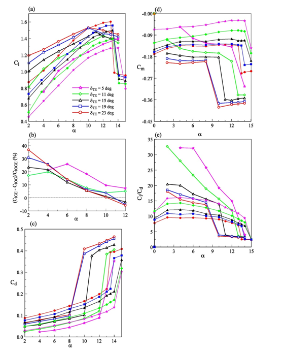
Finally, to provide a direct comparison of dTE on the flapped NACA 0015 airfoil in ground effect, the aerodynamic properties at h¢/c=2.5% as a function of δ TE MathType@MTEF@5@5@+= feaagKart1ev2aaatCvAUfeBSjuyZL2yd9gzLbvyNv2CaerbuLwBLn hiov2DGi1BTfMBaeXatLxBI9gBaerbd9wDYLwzYbItLDharqqtubsr 4rNCHbGeaGqkY=gjVeeu0dXdPqFfpec8Eeeu0xXdbba9frFj0=OqFf ea0dXdd9vqaq=JfrVkFHe9pgea0dXdar=Jb9hs0dXdbPYxe9vr0=vr 0=vqpWqaaeaabiGaciaacaqabeaadaqaaqaaaOqaaabaaaaaaaaape GaaeiTd8aadaWgaaWcbaWdbiaabsfacaqGfbaapaqabaaaaa@3999@ is presented in Figure 7. At a fixed ground distance,

    1. The Cl was always found to increase with increasing δ TE MathType@MTEF@5@5@+= feaagKart1ev2aaatCvAUfeBSjuyZL2yd9gzLbvyNv2CaerbuLwBLn hiov2DGi1BTfMBaeXatLxBI9gBaerbd9wDYLwzYbItLDharqqtubsr 4rNCHbGeaGqkY=gjVeeu0dXdPqFfpec8Eeeu0xXdbba9frFj0=OqFf ea0dXdd9vqaq=JfrVkFHe9pgea0dXdar=Jb9hs0dXdbPYxe9vr0=vr 0=vqpWqaaeaabiGaciaacaqabeaadaqaaqaaaOqaaabaaaaaaaaape GaaeiTd8aadaWgaaWcbaWdbiaabsfacaqGfbaapaqabaaaaa@3999@  (Figure 7a);
    2. The gain in Cl increment (i.e., ΔC l MathType@MTEF@5@5@+= feaagKart1ev2aaatCvAUfeBSjuyZL2yd9gzLbvyNv2CaerbuLwBLn hiov2DGi1BTfMBaeXatLxBI9gBaerbd9wDYLwzYbItLDharqqtubsr 4rNCHbGeaGqkY=gjVeeu0dXdPqFfpec8Eeeu0xXdbba9frFj0=OqFf ea0dXdd9vqaq=JfrVkFHe9pgea0dXdar=Jb9hs0dXdbPYxe9vr0=vr 0=vqpWqaaeaabiGaciaacaqabeaadaqaaqaaaOqaaabaaaaaaaaape GaaeiLdiaaboeapaWaaSbaaSqaa8qacaqGSbaapaqabaaaaa@398F@ ) was diminishing as δ TE MathType@MTEF@5@5@+= feaagKart1ev2aaatCvAUfeBSjuyZL2yd9gzLbvyNv2CaerbuLwBLn hiov2DGi1BTfMBaeXatLxBI9gBaerbd9wDYLwzYbItLDharqqtubsr 4rNCHbGeaGqkY=gjVeeu0dXdPqFfpec8Eeeu0xXdbba9frFj0=OqFf ea0dXdd9vqaq=JfrVkFHe9pgea0dXdar=Jb9hs0dXdbPYxe9vr0=vr 0=vqpWqaaeaabiGaciaacaqabeaadaqaaqaaaOqaaabaaaaaaaaape GaaeiTd8aadaWgaaWcbaWdbiaabsfacaqGfbaapaqabaaaaa@3999@ was increased (Figure 7b);
    3. The Cd was reduced with reducing δ TE MathType@MTEF@5@5@+= feaagKart1ev2aaatCvAUfeBSjuyZL2yd9gzLbvyNv2CaerbuLwBLn hiov2DGi1BTfMBaeXatLxBI9gBaerbd9wDYLwzYbItLDharqqtubsr 4rNCHbGeaGqkY=gjVeeu0dXdPqFfpec8Eeeu0xXdbba9frFj0=OqFf ea0dXdd9vqaq=JfrVkFHe9pgea0dXdar=Jb9hs0dXdbPYxe9vr0=vr 0=vqpWqaaeaabiGaciaacaqabeaadaqaaqaaaOqaaabaaaaaaaaape GaaeiTd8aadaWgaaWcbaWdbiaabsfacaqGfbaapaqabaaaaa@3999@ since the pressure drag became less dominant with decreasing δ TE MathType@MTEF@5@5@+= feaagKart1ev2aaatCvAUfeBSjuyZL2yd9gzLbvyNv2CaerbuLwBLn hiov2DGi1BTfMBaeXatLxBI9gBaerbd9wDYLwzYbItLDharqqtubsr 4rNCHbGeaGqkY=gjVeeu0dXdPqFfpec8Eeeu0xXdbba9frFj0=OqFf ea0dXdd9vqaq=JfrVkFHe9pgea0dXdar=Jb9hs0dXdbPYxe9vr0=vr 0=vqpWqaaeaabiGaciaacaqabeaadaqaaqaaaOqaaabaaaaaaaaape GaaeiTd8aadaWgaaWcbaWdbiaabsfacaqGfbaapaqabaaaaa@3999@  (Figure 7c); and

Figure 7 Variation of Aerodynamic coefficients with δ TE MathType@MTEF@5@5@+= feaagKart1ev2aaatCvAUfeBSjuyZL2yd9gzLbvyNv2CaerbuLwBLn hiov2DGi1BTfMBaeXatLxBI9gBaerbd9wDYLwzYbItLDharqqtubsr 4rNCHbGeaGqkY=gjVeeu0dXdPqFfpec8Eeeu0xXdbba9frFj0=OqFf ea0dXdd9vqaq=JfrVkFHe9pgea0dXdar=Jb9hs0dXdbPYxe9vr0=vr 0=vqpWqaaeaabiGaciaacaqabeaadaqaaqaaaOqaaiabes7aKnaaBa aaleaacaWGubGaamyraaqabaaaaa@39BA@  at fixed h’/c=2.5%. Open and solid symbols denote in ground effect and out-of-ground effect, respectively.

The nose-down Cm decreased with decreasing δ TE MathType@MTEF@5@5@+= feaagKart1ev2aaatCvAUfeBSjuyZL2yd9gzLbvyNv2CaerbuLwBLn hiov2DGi1BTfMBaeXatLxBI9gBaerbd9wDYLwzYbItLDharqqtubsr 4rNCHbGeaGqkY=gjVeeu0dXdPqFfpec8Eeeu0xXdbba9frFj0=OqFf ea0dXdd9vqaq=JfrVkFHe9pgea0dXdar=Jb9hs0dXdbPYxe9vr0=vr 0=vqpWqaaeaabiGaciaacaqabeaadaqaaqaaaOqaaabaaaaaaaaape GaaeiTd8aadaWgaaWcbaWdbiaabsfacaqGfbaapaqabaaaaa@3999@ , as a result of the reduced amount of flow trapped beneath the airfoil as δ TE MathType@MTEF@5@5@+= feaagKart1ev2aaatCvAUfeBSjuyZL2yd9gzLbvyNv2CaerbuLwBLn hiov2DGi1BTfMBaeXatLxBI9gBaerbd9wDYLwzYbItLDharqqtubsr 4rNCHbGeaGqkY=gjVeeu0dXdPqFfpec8Eeeu0xXdbba9frFj0=OqFf ea0dXdd9vqaq=JfrVkFHe9pgea0dXdar=Jb9hs0dXdbPYxe9vr0=vr 0=vqpWqaaeaabiGaciaacaqabeaadaqaaqaaaOqaaabaaaaaaaaape GaaeiTd8aadaWgaaWcbaWdbiaabsfacaqGfbaapaqabaaaaa@3999@  was reduced (Figure 7d). In short, the smallest trailing-edge flap deflection seemed to produce not only the smallest nose-down Cm and Cd but also the largest ΔC l MathType@MTEF@5@5@+= feaagKart1ev2aaatCvAUfeBSjuyZL2yd9gzLbvyNv2CaerbuLwBLn hiov2DGi1BTfMBaeXatLxBI9gBaerbd9wDYLwzYbItLDharqqtubsr 4rNCHbGeaGqkY=gjVeeu0dXdPqFfpec8Eeeu0xXdbba9frFj0=OqFf ea0dXdd9vqaq=JfrVkFHe9pgea0dXdar=Jb9hs0dXdbPYxe9vr0=vr 0=vqpWqaaeaabiGaciaacaqabeaadaqaaqaaaOqaaabaaaaaaaaape GaaeiLdiaaboeapaWaaSbaaSqaa8qacaqGSbaapaqabaaaaa@398F@ and the best lift-to-drag ratio among all δ TE MathType@MTEF@5@5@+= feaagKart1ev2aaatCvAUfeBSjuyZL2yd9gzLbvyNv2CaerbuLwBLn hiov2DGi1BTfMBaeXatLxBI9gBaerbd9wDYLwzYbItLDharqqtubsr 4rNCHbGeaGqkY=gjVeeu0dXdPqFfpec8Eeeu0xXdbba9frFj0=OqFf ea0dXdd9vqaq=JfrVkFHe9pgea0dXdar=Jb9hs0dXdbPYxe9vr0=vr 0=vqpWqaaeaabiGaciaacaqabeaadaqaaqaaaOqaaabaaaaaaaaape GaaeiTd8aadaWgaaWcbaWdbiaabsfacaqGfbaapaqabaaaaa@3999@  tested (Figure 7e).

Conclusion

The ground effect on the aerodynamic behavior of a NACA 0015 airfoil with a plain trailing-edge flap was investigated experimentally. For the unflapped airfoil, the ground effect produced a negative lift for α 3 o MathType@MTEF@5@5@+= feaagKart1ev2aaatCvAUfeBSjuyZL2yd9gzLbvyNv2CaerbuLwBLn hiov2DGi1BTfMBaeXatLxBI9gBaerbd9wDYLwzYbItLDharqqtubsr 4rNCHbGeaGqkY=gjVeeu0dXdPqFfpec8Eeeu0xXdbba9frFj0=OqFf ea0dXdd9vqaq=JfrVkFHe9pgea0dXdar=Jb9hs0dXdbPYxe9vr0=vr 0=vqpWqaaeaabiGaciaacaqabeaadaqaaqaaaOqaaabaaaaaaaaape GaaeySdiaaykW7caaMc8UaaGPaVlabgsMiJkaaykW7caqGZaWdamaa CaaaleqabaWdbiaab+gaaaaaaa@4172@  while became positive for α> 3 o MathType@MTEF@5@5@+= feaagKart1ev2aaatCvAUfeBSjuyZL2yd9gzLbvyNv2CaerbuLwBLn hiov2DGi1BTfMBaeXatLxBI9gBaerbd9wDYLwzYbItLDharqqtubsr 4rNCHbGeaGqkY=gjVeeu0dXdPqFfpec8Eeeu0xXdbba9frFj0=OqFf ea0dXdd9vqaq=JfrVkFHe9pgea0dXdar=Jb9hs0dXdbPYxe9vr0=vr 0=vqpWqaaeaabiGaciaacaqabeaadaqaaqaaaOqaaabaaaaaaaaape GaaeySdiaaykW7caaMc8UaaGPaVlaab6dacaaMc8Uaae4ma8aadaah aaWcbeqaa8qacaqGVbaaaaaa@407E@ . The lift increment was also found to increase with reducing ground distance. The ground effect, however, became less impactful for h/c>15%. The presence of the ground also caused an increased in the drag and nose-down pitching moment compared to their out-of-ground effect counterparts.

For the flapped airfoil in ground effect, the RAM pressure and the suction peak continued to increase as the ground was approached, attributing to the increased amounts of flow trapped underneath the airfoil. The RAM pressure and lift augmentation also increased as the trailing-edge flap was deflected. The percentage of lift increment was, however, found to be most significant in the low- α MathType@MTEF@5@5@+= feaagKart1ev2aaatCvAUfeBSjuyZL2yd9gzLbvyNv2CaerbuLwBLn hiov2DGi1BTfMBaeXatLxBI9gBaerbd9wDYLwzYbItLDharqqtubsr 4rNCHbGeaGqkY=gjVeeu0dXdPqFfpec8Eeeu0xXdbba9frFj0=OqFf ea0dXdd9vqaq=JfrVkFHe9pgea0dXdar=Jb9hs0dXdbPYxe9vr0=vr 0=vqpWqaaeaabiGaciaacaqabeaadaqaaqaaaOqaaabaaaaaaaaape GaaeySdaaa@379D@  regime. The closer the ground proximity the earlier the airfoil stall was observed. Meanwhile, the drag was, however, reduced while the nose-down pitching moment was increased with reducing ground distance. Overall, smaller plain flap deflections in ground effect produced the best lift increment and lift-to-drag ratio compared to larger flap deflections. It is therefore suggested that a simple plain TEF deflected at small deflections, especially in extreme ground proximity, can greatly regulate the aerodynamic efficiency of the WIG craft.

Acknowledgements

The authors would like to thank L.S. Ko for his help with the figure preparation. This work was supported by the Natural Science and Engineering Research Council of Canada (NSERC).

Conflict of interest

Author declares that there is no conflict of interest.

References

  1. Divitiis ND. Performance and stability of a winged vehicle in ground effect. J Aircraft. 2005;42(1):148-157.
  2. Angle EM, Brian OM, Franz AP, et al. Pitch stability analysis of an airfoil in ground effect. J Aircraft. 2009;46(3):756‒762.
  3. Wang H, Teo CJ, Khoo BC, et al. Computational aerodynamics and flight stability of wing-in-ground (WIG) craft. Procedia Eng. 2013;67:15‒24.
  4. Tomaru H, Kohama Y. Experiments on wing in ground effect with fixed ground plates. Proceedings of the 2nd JSME-KSME Fluids Eng. Conference, Japan Society of Mech Engrs, Japan: Tokyo; 1990. p. 370‒373.
  5. Hsiun CM, Chen CK. Aerodynamic characteristics of a two-dimensional airfoil with ground effect. J Aircraft. 1996;33(2):386‒392.
  6. Moore N, Wilson PA, Peters AJ. An investigation into wing in ground effect airfoil geometry. In RTO-MP-095, NATO RTO, Fluid Structure Interactions Group, Symposium on Challenges in Dynamics, System Identification, Control and Handling Qualities for Land, Air, Sea and Space Vehicles, Berlin, Germany; 2002. p. 20.
  7. Ahmed MR, Sharma SD. An investigation on the aerodynamics of a symmetric airfoil in ground effect. Expt Thermal & Fluid Sci. 2005;29(6):633‒647.
  8. Ahmed MR, Takasaki T, Kohama Y. Aerodynamics of a NACA 4412 airfoil in ground effect. AIAA J. 2007;45(1):37‒47.
  9. Luo SC, Chen YS. Ground effect on flow past a wing with a NACA 0015 cross-section. Expt thermal & Fluid Sci. 2012;40:18‒28.
  10. Liang H, Zhou L, Zong Z, et al. An analytical investigation of two-dimensional and three-dimensional biplanes operating in the vicinity of a free surface. J Marine Sci & Tech. 2013;18(1):12‒31.
  11. Liang H, Wang X, Zou L, et al. Numerical study of two-dimensional heaving airfoils in ground effect. J Fluids & Struc 2014;48:188‒202.
  12. Lee T, Majeed A, Siddiqui B, et al. Impact of ground proximity on the aerodynamic properties of an unsteady airfoil. Proceedings of the Institution of Mechanical Engineers, Part G: Journal of Aerospace Engineering. 2017.
  13. Rozhdestvensky KV. Wing-in-ground effect vehicles. Prog in Aero Sci. 2006;42(3):211‒283.
  14. Steinbach D. Comment on “Aerodynamic characteristics of a two-dimensional airfoil with ground effects”. J 1997;34(3):455‒456.
  15. Ockfen AE, Matveev K. Aerodynamic characteristics of NACA 4412 airfoil section with flap in extreme ground effect. J Naval Architecture and Ocean Eng. 2009;1(1):1‒12.
  16. Zerihan J, Zhang X. Aerodynamics of a single-element wing in ground effect. J Aircraft. 2000;37(6):1058‒1064.
  17. Zhang X, Zerihan J. Aerodynamics of a double-element wing in ground effect. AIAA J. 2003;41(6):1007‒1016.
Creative Commons Attribution License

©2018 Dionne, et al. This is an open access article distributed under the terms of the, which permits unrestricted use, distribution, and build upon your work non-commercially.