eISSN: 2577-8242


Technical Paper Volume 3 Issue 2
1Department of Aerospace Engineering, GITAM University, India
2Department of Mechanical Engineering, GITAM University, India
Correspondence: Md Akhtar khan, Department of Aerospace Engineering, GITAM University, Hyderabad, India, Tel 6302812891
Received: May 25, 2019 | Published: June 26, 2019
Citation: Khan A, Padhy C. Aerodynamic and structural analysis of bio-mimetic corrugated wing. Fluid Mech Res Int J. 2019;3(2):61-67. DOI: 10.15406/fmrij.2019.03.00053
This work includes the aerodynamic and static structural analysis of newly designed bio-mimetic corrugated aerofoil inspired from dragonfly forewing. Dragonfly corrugated aerofoil structure used in this research comprised of basal wing section located near the radius of the forewing. These corrugations define the stressed skin structure composed of grider-like veins structure and thin cuticle membrane which provides sophisticated mechanical advantage for resisting longitudinal bending while facilitating wing camber and torsion. Dragonflies are known for their impressive flight performance .They carry aerodynamic and inertial loads. A computational analysis is done on a newly designed dragonfly corrugated aerofoil at Reynolds number of 15632, where flow is assumed to be laminar, steady, incompressible and two dimensional. The research comprises of the aerodynamic flow analysis of 2-D dragonfly corrugated aerofoil and static structural analysis using Ansys Fluent and Ansys Mechanical APDL. It is found that the design criteria being used and simulation carried out on corrugated aerofoil is giving much better results compared to earlier studies. The structural analysis also shows that it can resist maximum pressure loads and provides high rigidity to the span of the wing. These finding enhances the knowledge of insect inspired corrugated wing structure and facilitate the application for improved design of artificial wings for MAVs and UAVs.
Keywords: dragonfly, 2-d corrugated aerofoil, reynolds number, ansys fluent, ansys mechanical apdl, uavs, mavs
CFD, computational fluid dynamics; AoA, angle of attack
ρ Density of air, kg/m3
v Free-stream velocity, m/s
c chord length of the aerofoil, m
α Angle of attack
µ Dynamic viscosity, Pa.s
L Lift force, N
D Drag Force, N
CL Lift Coefficient
CD Drag Coefficient
Re Reynolds Number [ρVl /µ]
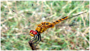
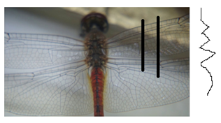
The approach can unlock the design principles of the wings of one of nature’s most remarkable aeronauts, the dragonfly. Dragonfly wings are complex biological composite structures and consist of two main structural components, an ultra thin membrane supported by reinforcing hollow veins. In the present study we used ANSYS-15 for computational aerodynamics analysis and structural analysis of newly designed corrugated structure inspired from the forewing of ‘Pantala flavescens’ dragonfly. Dragonfly being a natural flyer the vein and the membrane structure are flexible in nature and it is difficult to predict the behavior of dragonfly corrugated wing during flight condition as shown in Figure 1a and Figure 1b.
(a) (b)
The dragonfly corrugated airfoil used in this study is wavy in nature (i.e. consists of valley) and has the chord length of 110 mm. The corrugated design is with increasing corrugation angles with increasing peak heights and having a curved profile at the trailing edge as shown in Figure 2.1
Kesel2 noticed trapped vortices present in the folds that serve to change the effective profile of the airfoil. With the advent of bio-inspired aerial vehicle, it has become clear that there is much that can be learnt from insect flight that could be translated into engineered systems. The negative pressure developed in these corrugations contributes to the excessive lift.
Okama et al.,3 isolated the influence of different geometrical parameters and showed that the surface texture or the roughness of wings results in an increased maximum lift coefficient, CLmax and increases maximum lift to drag ratio (L/D)max.
Dragonfly wings shows complete corrugation with the stems of the main longitudinal veins and the composite veins are linked at the nodus. In addition, reinforcement can be provided by the cross-veins of the nodus. Nodus prevents fracture on the vein structure during flight.4
The resolution of the grids around the wing is particularly important as it determines the accuracy of the analysis. Aerodynamic performance of corrugated aerofoil is carried out by using structure grid Navier-stokes method. The size of the grid that comes in contact with wing is determined as 1% of the boundary layer thickness at the wing trailing edge Table 1 Computational domain (Figure 3 & 4).
|
Domain size |
910x600 mm |
|
Number of nodes |
434230 |
|
Min orthogonality |
0.511 |
|
Velocity |
2.1 m/s |
|
Dynamic viscosity(µ) |
1.789x10⁻⁵ |
|
Density |
1.225 kg/m3 |
Table 1 Computational domain
(1)
(2)
(3)
(4)
(5)
where, s = b×c, for 2-D wing b=1
Gliding Ratio = (6)
CFD analysis results of corrugated wing
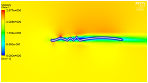
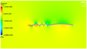
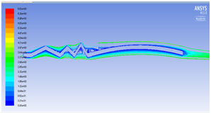
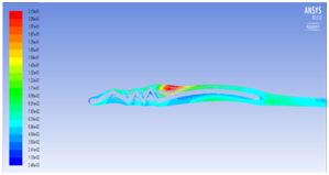
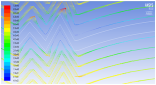
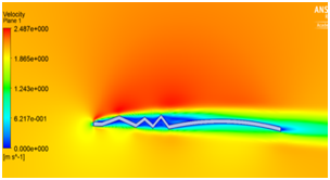
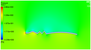
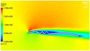
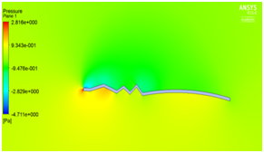
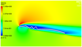
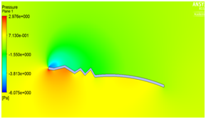
We have seen that velocity is maximum at the peaks and minimum in the valleys and pressure is maximum at the stagnation point as illustrated in Figure 5a and Figure 5b. The beauty of this design is that even at zero degree angle of attack the vortices are trapped inside the valleys as shown in Figure 5c which helps in delaying flow separation. Instead as the angle of attack of the corrugated wing increases from 2° to 8° as shown in Figure 5e to Figure 5j the corresponding lift increases which increases the aerodynamic performance of the wing indicates the suitability of the pleated corrugated aerofoil for MAVs and UAVs. The stalling angle for this corrugated wing is in the range of 6°-8°where lift starts decreasing gradually.5
(a) (b)
(c) (d)
(e) (f)
(g) (h)
(i) (j)
(k)
Figure 5 (a) Pressure plot at α = 0° (b) velocity plot at α=0° (c) velocity pathline at α=0° (d)Turbulence contour at α = 0° (e) velocity vector showing reverse flow at α = 0°(f) velocity plot at α = 2° (g) Pressure plot at α = 2(h) velocity plot at α = 4° (i) Pressure plot at α = 4° (j) velocity plot at α =8° (k) Pressure plot at α = 8°.
CFD analysis results of flat plate
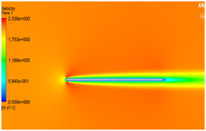
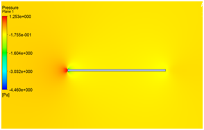
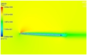
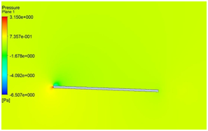
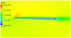
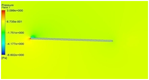
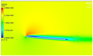
Since, the flat plate is put in a flow with zero incidences; the flow at the plate surface is slowed down because of the surface friction. This region of slowed down flow becomes even larger and produces skin-friction drag which increases with the increase in angle of attack as shown in Figure 6.6
(a) (b)
(c) (d)
(e) (f)
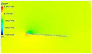
(g) (h)
Figure 6 (a) velocity at α = 0° (b) pressure distribution at α = 0° (c) velocity distribution at α = 2° (d) pressure distribution at α = 2° (e) velocity distribution at α = 4° (f) pressure distribution at α = 4° (g) velocity distribution at α = 8° (h) pressure distribution at α = 8°.
The computational results of the corrugated wing and flat plate are compared at different angle of attack i.e. (0°, 2°, 4° and 8°). The value of CL , CD and L/D is calculated and plotted in terms of graph Table 2.7–9
|
|
Wing type |
CL at (α = 0°, 2°,4°,8°) |
CD at (α = 0°, 2°,4°,8°) |
CL/CD at (α = 0°, 2°,4°,8°) |
|
0°- 0.2177 |
0°- 0.0670 |
0°- 3.25 |
||
|
a |
Cor-wing |
2°- 0.4340 |
2°- 0.0696 |
2°- 6.229 |
|
4°- 0.6327 |
4°- 0.0797 |
4°- 7.933 |
||
|
8° - 0.9465 |
8° - 0.1232 |
8° - 7.677 |
||
|
0°- 0 |
0°- 0.0347 |
0°- 0 |
||
|
b |
Flat Plate |
2°- 0.2209 |
2°- 0.0522 |
2°- 4.12 |
|
4°- 0.2539 |
4°- 0.05565 |
4°- 4.56 |
||
|
|
|
8° - 0.4412 |
8° - 0.0683 |
8° - 5.45 |
Table 2 Comparison table
The graph in Figure 7, which is known as the lift curve, shows that as the angle of attack increases the curve for corrugated aerofoil is linear over a considerable range giving high lift coefficient compared to flat plate. In Figure 8 it is observed that initially coefficient of drag decreases up to 6° angle of attack and then it increases after reaching the stalling point at a particular speed. The graph in Figure 9 clearly shows that the performance of corrugated aerofoil is much better compared to its counterpart.
Static structural analysis
We carried out the structural analysis for the corrugated model using the ANSYS Mechanical APDL 15.0 software. The Young's modulus or modulus of elasticity is considered as, E = 6.1 GPa and Poisson's ratio, ν = 0.49 and the density, ρ=1200 kg/m3. The corrugated model section is considered as a beam and is restricted to all degrees of freedom at the leading edge. The load applied on the beam is considered as the pressure force and is distributed evenly on the entire beam surface.
From the Figure 10(b), we can see that the maximum displacement in z direction at the trailing edge is 0.199×10⁻⁴ mm and the minimum deflection is at the leading edge. The maximum Von-misses stress obtained is 0.370×10⁻³ N/mm2 at the leading edge or at the root of the corrugated aerofoil.
It is found that the design criteria being used and simulation carried out on the corrugated wing at low Reynolds number is giving much better results. The flow separates from the corrugation instantly reattaches to the upper surface and get trapped in the valleys which delays flow separation. The aerodynamic performance i.e. L/D ratio of the corrugated wing increases which improves the gliding of the dragonfly.10–12 The structural analysis shows that the corrugated structure can withstand inertial loads and shearing. In corrugated wing structure if one member fails the other member can withstand that load which prevents the dragonfly wing fracture during flight condition. The wing deformation during down stroke due to camber causes the wing being more rigid to forces applied from the concave side than from the convex side resulting in high stiffer wings and more precised for flapping MAVs. Hence, it is concluded that the corrugated wing can withstand both aerodynamic and structural load which is most suitable for future MAVs and UAVs.
None.
The authors declares there is no conflicts of interest.

©2019 Khan, et al. This is an open access article distributed under the terms of the, which permits unrestricted use, distribution, and build upon your work non-commercially.