Mathematical model of ship motion is considered as an artificial brain deciding the capability of a bridge simulation system and ensuring the reality of ship maneuvering. Due to the huge development of shipbuilding industry ships have been being equipped with a variety of non-conventional propellers and rudders the existing mathematical models need to be improved accordingly. Moreover, training simulators nowadays require more external and environmental forces to be integrated into the system for more reality. This study aims to review previous studies on mathematical models of ship motions and proposes a development to the synthetic model of forces for systematically and simply simulating ship motion in six degrees of freedom in real-time mode.
Keywords: mathematical modeling, hydrodynamics forces, ship hydrodynamics, ship simulation
The mathematical model of ship motions is considered as an artificial brain deciding the processing capability of a bridge simulation system and ensuring the reality of ship maneuvering. Due to the quick development of shipping industry, ships, nowadays, have been being equipped with advanced propellers such as nozzled, azipod, water jets, surface-piercing propellers, contra-rotating propellers, azimuth propellers, Voith–Schneider propellers etc. The variety in types and numbers of propellers and rudders fixed on the ship causing a challenge for calculating and computerizing all of the forces impacting to ship hulls on simulation systems.
By establishing a mathematical model based on Newton’s equation, hydrostatic, hydrodynamic, aerodynamic theories with empirical data the status equations of ship motions are set up. A simple mathematical model including one equation was introduced by NOMOTO K (1957). Davidson and Schiff (1946) described yawing and drifting in 2 DOF. Norrbin (1971), Inoue (1981), Ankudinov (1993) and other researchers developed in 3 DOF model including surging, swaying, yawing. Eda (1980), Hirano (1980) and Oltmann (1993) described 4 DOF model by adding rolling motion. By adding heaving and pitching motions Ankudinov (1983) and Hooft & Pieffers (1988) did establish 6DOF model.1,2 Thor I Fossen3 systemized 6 DOF model with status equations3 in which coefficients were described in the form of a matrix:
(1)
(2)
Where M is generalized mass matrix of the ship and added mass, CS(v), CA(V) are Coriolis and centripetal matrixes of the ship and added mass due to motion or rotation about the initial frame, D,D(v) and Dn(v) are damping matrixes;
is velocity matrix,
is acceleration matrix.
is generalized gravitational/buoyancy forces and moments. f=[X,Y,Z,K,M,N]T is matrix of external forces and moments effecting to the ship (Table 1).
DOF |
Description |
Velocities |
Forces |
1 |
surge - motion in x direction |
u |
X |
2 |
sway - motion in y direction |
v |
Y |
3 |
heave - motion in z direction |
w |
Z |
4 |
roll – rotation about x axis |
p |
K |
5 |
pitch - rotation about y axis |
q |
M |
6 |
yaw - rotation about z axis |
r |
N |
Table 1 Parameters defined in the body-fixed reference frame
The principal for calculating of added mass is based on work of Ursell4 and Frank5 for an arbitrary symmetric cross section. Then Keil6 introduced a method for any arbitrary water depth based on a variation of the method of Ursell4 with Lewis conformal mapping. Frank5 described the pulsating source method for deep water.
Nils Salvesen et al.7 introduced new method to predict heave, pitch, sway, roll and yaw motions as well as wave-induced vertical and horizontal shear forces, bending moments, and torsional moments for a ship advancing at a constant speed with arbitrary heading in regular waves.
For calculating damping coefficients a simple set of equations is presented by Society of Naval Architects and Marine Engineers (SNAME) in 3 DOFs including surge, sway and yaw.8 Fedyaevsky et al.9 introduced equations to calculate cross-flow Drag in sway and yaw. Nils Salvesen et al.7 suggested a method to calculate damping components in “Ship Motions and Sealoads”.
Recent studies on the calculation of ship resistance have tended to improve the accuracy of previous methods or apply computational fluid dynamics (CFD).
K Zelazny10 introduced a method to improve the accuracy of ship resistance at preliminary stages of design. Mucha et al.11 had a validation study on numerical prediction of resistance in shallow water based on the solution of the Reynolds-averaged Navier-Stokes (RANS) equations, a Rankine Panel method and a method based on slender-body. The application of CFD can be typically referred to the study of Yasser M Ahmed et al.12 For roll damping coefficients, it can be referred to study of Frederick Jaouen et al.13 and the calculation of Yang Bo et al.14 by using numerical simulation based on CFD. Burak Yildiz et al.15 introduced a URANS prediction of roll damping due to the effects of viscosity based on CFD while Min Gu et al.16 presented a roll damping calculation based on numerical simulation on the RANS model in calm water. In 2017, D Sathyaseelan et al.17 introduced an efficient Legendre wavelet spectral method (LWSM) to ship roll motion model for investigating the nonlinear damping coefficients.
The forces f=[X,Y,Z,K,M,N]T includes ship propulsion forces and external forces caused by environmental effects such as current, wind, wave, squat, bank effect, ship interaction, anchor, mooring line, towing, grounding, collision. The calculations of these forces were solved and published separately by various researches.
The propulsion forces are created by the ship’s propellers and rudders. Since there is a wide range of various types of propellers and rudders, the methods to calculate forces are diversified and have been solved by separate studies which can be referred to as Habil Nikolai Kornev,18 John P. Breslin et al.,19 Øyvind Notland Smogeli,20 Tran Cong Nghi,21 Edward M Lewandowski.8
The environmental forces caused by the current, wind, wave can be estimated by referring to Thor Fossen,3 Journée and Adegeest,22 Edward M Lewandowski8 and other various researches.
The ship to ship interaction can be based on the paper of Wang S23and Cummins WE.24 The estimation of squat can be referred to the formula suggested by Gourlay et al.25 based on slender-body theory while the bank effect can be determined by application of the description of Evert Lataire et al.26
The external forces caused by the anchor, mooring line, towing, grounding, collision can be described in the same approach. Each certain force can be considered as single component affecting the ship as a force vector at given position. Therefore, these forces can be described according to the principle of basic physics.
As the above mentioned, the methods to calculate every single force components are available in previous studies. However, number and properties of these forces vary continuously during the real-time ship motion. The problem, therefore, is how to develop an equation to describe all unlimited force components that have not been posted in previous researches yet.
This paper is aimed to focus on the systematization of all force components and suggest a total force model
for the purpose of ship simulation in real-time motion in 6 DOFs.
Basically, forces effecting on the ship hull consist of:
- Hydrodynamic forces: include Coriolis forces and damping forces. These forces are considered calculated in the hydrodynamic coefficients C(v), D(v).
- Hydrostatic forces: include buoyancy forces and restoring moments.
- Propulsion forces: are created by propellers and rudders.
- External forces: consist of forces caused by current, wind, wave, squat, bank suction, interaction of ships, mooring line, towing, tug support, anchor, collision, and grounding (Figure 1).
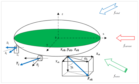
Figure 1 Describing force components effecting on ship’s hull.
In practice, the force components are very complex depending strictly on the ship propulsion system and loading condition and environmental condition. They change time to time at every real-time condition. The total forces can be described:
(3)
Where:
: matrix of restoring forces and moments
Propulsion force group:
fr : matrix of forces and moments caused by rudder system
fp: matrix of forces and moments caused by propeller system
External force group:
fcu : matrix of forces and moments created by current
fwi : matrix of forces and moments created by wind
fwa : matrix of forces and moments created by wave
fsq : matrix of forces and moments created by squat
fbk : matrix of forces and moments created by bank effect
fir : matrix of forces and moments created by ship to ship interaction
far : matrix of forces and moments created by ship anchors
fml : matrix of forces and moments created mooring lines
fpl : matrix of forces and moments created by towing lines
fph : matrix of forces and moments created by tug pushing
fgr: matrix of forces and moments created by grounding
fcl: matrix of forces and moments created by collision
For simpler expression, the external forces can be grouped as the force matrix
:
(4)
Hereafter, Fi is defined as the ith force (Figure 2),
as azimuth angle and
as declination angle of the forces vector in oyz frame at a position Oi:
(5)
(6)
Based on basic physics and mathematics, the mathematical model of total forces and moments of surfing, swaying and heaving motions are expressed:
(7)
(8)
(9)
Thus, the moment in rolling, pitching and yawing rotations are obtained:
(10)
(11)
(12)
Where xi, yi, zi are lever arm of the force Fi over axis OX, OY, OZ: xi = OXi ; yi = OYi ; zi = OZi.
Thus, the matrix of total forces and moments:
(13)
(14)
(15)
Where,
is restoring force matrix;
is force matrix of the ith rudder;
is force matrix of the jth propeller.
is force matrix of the kth external forces.
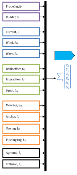
Figure 2 Describing components of the ith force.
With such the calculation, all the forces can be considered as separate components i
th, j
th, k
th. This enables to calculate and add single force into the general equations (2) in real-time simulation.
The computerizing algorithm (Figure 3) for simulating ship motions is set up based on the general equation (2). General diagram for calculating all forces are described:
For this study, the ship model Container 18000 TEU triple E and Genting Dream are used (Table 2).
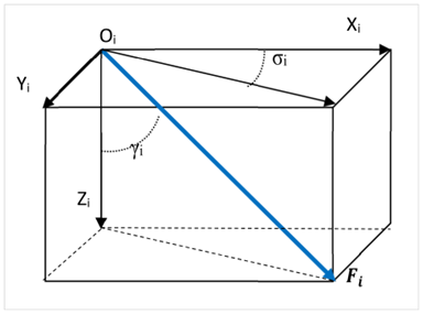
Figure 3 Diagram of total forces affecting to ship motions.
Ship Model |
Triple E |
Genting Dream |
Type |
Container |
Cruise |
L (m) |
399 |
335.3 |
B (m) |
59 |
39.7 |
T (m) |
16 |
8.3 |
Displ. (MT) |
257,343 |
70,330 |
Propulsion |
2 conventional rudders/propellers 2 bow thrusters |
2 azipod propellers/3 bow thrusters |
Table 2 Particulars of sample models
For assessing the propriety of the established formula, the algorithm is transferred into Matlab in the full equation (2). The hydrodynamics coefficients C(v), D(v) are referred to previous studies.27,28 For simplifying the assessment, it is assumed that the ship is moving in calm water without external forces. In this case, the propulsion forces, hydrodynamic forces, and hydrostatic forces are applied. The other external forces can be added separately without influencing to final results of the method Figures 5−8.
The plotting curves in MATLAB of the sample models show that the forces and moments caused by the propulsion system are reasonably and logically.
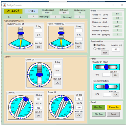
Figure 4 Control units are made in Matlab for different types of propellers/rudders.
The above results are extracted from the Genting Dream model:
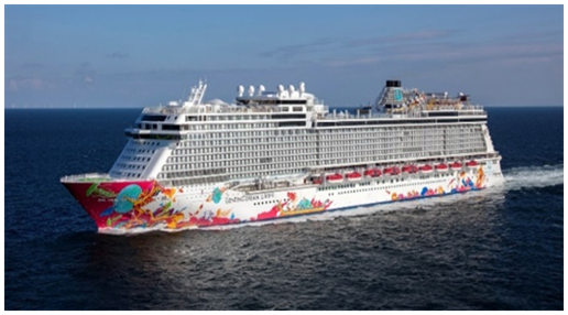
Figure 5 Genting Dream model.

Figure 6 Wet area of the model created by Matlab.
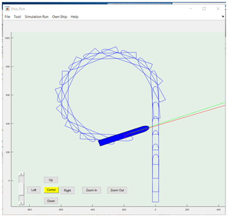
Figure 7 Turning circle of the model when applying rudder turning 15 degrees on portside.
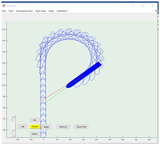
Figure 8 Turning circle of the model when applying rudder turning 20 degrees on starboardside.
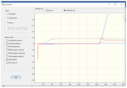
Figure 9 Turning parameters of the model when applying rudder turning 20 degree on starboardside.
Due to the limitation of time and work for studying, only propulsion forces in combination with hydrodynamic forces and hydrostatic forces are simulated and tested. However, the other external forces can be added into the equation (2) separately in other steps.


