eISSN: 2641-936X


Research Article Volume 2 Issue 6
Department of New Product Development, United Kingdom
Correspondence: Balazs Novak, Lucy Electric, Department of New Product Development, Howland Road, Thame, United Kingdom
Received: May 09, 2017 | Published: November 29, 2018
Citation: Novak B. Investigation of asymmetric power distribution in balanced three-phase systems in planar arrangement. Electric Electron Tech Open Acc J. 2018;2(6):335-340. DOI: 10.15406/eetoaj.2018.02.00038
The paper investigates the cause of asymmetry in the time-average power-density distribution in the conductors of three-phase systems arranged in horizontal spatial symmetry and loaded by a balanced three-phase current. Although this asymmetry has been known for decades, the degree of it is usually minor in practical cases of electric power transmission and distribution, and sometimes even professional people doubt its existence. It also contributes to this situation that several technical documents dealing with losses in conductors neglect the asymmetry, and in research papers its computation is usually based on some numerical method liable to rounding errors. The discussion here avoids numerical calculations, and proves without the need of academic level mathematics that the reason of asymmetry is the resistance of the conductors. All the reader has to know to understand the deductions are Faraday’s law of induction, Ampere’s law, and the trigonometric functions.
Keywords: busbars, cables, current distribution, current density, skin effect, electromagnetic fields
The steady–state temperature rise has always been a crucial question for switchgear developers and designers of cable systems. For its calculation, it is necessary to know the Joule-losses generated in the conductors. In case of ac systems, these losses are time-average losses, since the thermal time constants of the electrical systems are higher by orders of magnitude than the time constants of the electrical circuits or the cycle times at power frequency loads. To calculate the time-average loss, the designers have to determine the ac resistance, or practically the rms current-density distribution first. By the end of the 19th century, the mathematical theory describing the phenomenon of ac current density distribution in conductors has already been developed. During the first half of the 1900s, researchers were trying to find easy to use analytical formulae to determine this distribution and primarily the ac resistance and losses of conductors. This was not a simple task, since even describing an isolated circular conductor needed the use of Bessel functions, which can be expressed only in the form of mathematical series. Without computers, finding an exact solution was practically impossible at that time. The first formulae deduced by Russel, Dwight, and others1–4 were difficult to evaluate or liable to serious errors. Arnold contributed a lot to the field by providing simpler and more reliable closed, approximating formulae for the ac resistance. He dealt with single5,6 and three–phase arrangements of circular7 and rectangular8 conductors, and investigated the effect of sheaths on the losses as well.9 By applying approximations for different conductor arrangements with different conditions, he could calculate the ac resistance usually within a one percent error margin. Neher and McGrath10 also dealt with the problem and deduced closed expressions for losses and ampacity of cable systems laid in triangular formation. There were analytical investigations also of arbitrary arrangements of conductors having the same cross section and resistivity by Arnold, Heyda and others11,12 All these results still appear today in cable standards 13 and in technical brochures.14,15
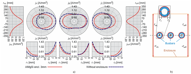
The advances of computer technology made it possible to determine the current density distribution in solid conductors more accurately. Different numerical methods like finite difference (FDM), finite element (FEM) or boundary element (BEM) has been developed and used for solving similar problems16–18 not to mention the precise solution of the analytical equations containing complex mathematical series19–23 even for conductors with arbitrary cross sections.24 The accuracy of the numerical calculations depends on the discretization of the models, for instance, in case of FEM, on the mesh size. Engineers have been using these sophisticated technologies for several years now. When they investigate conductors having significant cross-section in three-phase ac systems, be these conductors the busbars of a gas insulated switchgear (GIS) or the cores of power cables, they often run into the phenomenon of asymmetric rms current-density and loss distribution. They see that the distribution of the time-average loss can be asymmetric even if the geometric arrangement has a planar symmetry and the conductors carry balanced three-phase currents. The phenomenon usually appears 25,26 in flat configurations with all conductors having the same material and cross section and the two outer conductors being at the same distance from the middle one, like in Figure 1. (The diagrams in Figure 1a show the distribution of rms current-density amplitude over the busbar surfaces of a GIS, as results of FE simulations. The positions of the polar diagrams indicate the relative positions of the busbars. Within one polar diagram, the distance from the centre is proportional to the calculated value, whereas the angular position is the point’s angular position on the surface. The bottom diagrams show the current distribution in the cross section in the horizontal symmetry plane, r1 and r2 indicate the thickness of the tubes. The side diagrams plot the eddy current distribution over the inner surface of the sidewalls; rWL and rwR are the left and right enclosure wall heights from the horizontal symmetry plane (Figure 1b). In this example, asymmetry can be clearly observed both with and without an enclosure, although the case of three bare conductors without any additional conductors, like a sheath or enclosure, is more interesting for us (dashed line). Some people take this asymmetry for granted since it appears in all calculations, however small and negligible its degree is. Other ones consider the asymmetry as a minor error of the numerical approximations. Why would they think other, if even the cable standard13 and documents for practicing engineers dealing with busbar losses15 do not distinguish between the outer conductors? The IEC standard provides the same proximity effect factor for the two outer conductors, and differentiates between lagging and leading phase loss factors only for sheaths. In our case, sheath does not cover the three conductors. In Arnold’s original paper dealing with similar arrangements7 the two outer conductors also had the same ac resistances, not indicating any asymmetry. At this point, we must note that Heyda has shown with analytical expressions valid for an arbitrary system of parallel conductors that asymmetry does exist in the arrangements of Figure 1.11 His equation “predicts the surprising, but well known result that the losses in the two outer conductors differ from each other, the difference arising from the phase sequence”. Nevertheless, we must also note that according to Arnold12 Heyda’s equation “appears to be correct for an arbitrary number of conductors with their axes all in the same straight line” (configuration of Figure 1). “Its accuracy for conductors not in the same straight line is more doubtful; for example, it appears to indicate different losses in the three conductors of the symmetrically arranged 3-phase system”, “which considerations of symmetry would show to be impossible”. Can an equation be a proof, if it appears to be correct in one specific case but is definitely wrong in another?
In short, we can say that the asymmetry of current density and loss distribution in the flat, symmetrical conductor configuration of three bare conductors without any enclosure or sheath has been well known for decades, but there are still sceptics today, who doubt this fact. The sceptics say that the minor deviation in the symmetry lies in the nature of all computer calculations: the approximation of reality. For instance, a finite element mesh can differ on the two sides of the symmetry plane leading to asymmetric results, not to mention the rounding errors of the computations. All in all, the question is the following. What is the cause of the asymmetric time-average loss distribution in a three-phase ac system where the conductors are arranged in planar symmetry and loaded with a balanced three-phase current? Is there a real cause, or are we the victims of only an illusion created by our computers? This paper gives an unquestionable proof and unveils the culprit responsible for the phenomenon. The reader shall not search for any new formulae or methods of loss calculation here; our predecessors have already provided such. However, in the age of computers and commercially available software for numerical calculations, it is important that engineers clearly understand the physical phenomena they deal with. This work helps in this understanding. It provides a deduction based purely on basic physical considerations and laws, which do not necessitate the use of computers and the hard-to-follow academic level mathematics. Computers were used only for the illustrations and the numerical examples.
In pairs but never touching
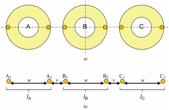
First of all, let us put the previous question the following way. What condition has to be satisfied to obtain an asymmetric rms current-density amplitude distribution to the vertical symmetry plane in the arrangement of Figure 2? (Subsequently, current density distribution or current distribution will generally refer to the distribution of rms amplitudes in this paper.) If we manage to find a well definable condition, we will be able to decide which cases satisfy it. Let us divide the infinite long three-phase busbar system arranged in planar symmetry in Figure 2a into current filaments or elementary conductors. From these, let us select two filaments in the horizontal symmetry plane from each of the busbars such, that these two filaments are symmetrical within the corresponding busbar. Figure 2b shows the conductor arrangement consisting of these elementary conductors without the remaining parts of the busbars. If, in case of balanced three-phase loading, the rms current is not equal between the conductor pairs A1-C2, A2-C1 or B1-B2, then the current density distribution in the busbars will not be symmetric either. Consequently, if we can show that different amount of current flows for instance in the elementary conductors A1 and C2, then the existence of asymmetric current-density distribution is proved.
Twelve angry unknowns
An obvious approach to determine the current distribution in the conductors of Figure 2b is to start with the impedance matrix of the conductor system. Considering the self and mutual impedances (Z1,1… Z3p,k), we can create a system of linear equations, in which the unknowns are the complex currents (I1 … Ik) and the voltage drops along the conductors (ΔVA, ΔVB, ΔVC). By denoting the number of filaments in one conductor by p, and the total number of filaments by k=3p, we can write the following equations:
(1)
Additionally, we know that the phase currents (IA, IB, IC) are the sum of the corresponding filamentary currents:
(2)
Since we are not interested in the voltage drops along the conductors, these can be easily eliminated from (1), and we can finally have k equations with k complex unknowns for the filamentary currents. If we take the amplitudes and phase angles of these currents into account separately, then we can say we have twelve real unknowns in our simple model, where p=2 and k=6 (Figure 3a). When we determine the self and mutual inductances, then the radii of the conductors cannot be zero, we have to model them as tiny pipes having finite radii. Alternatively, we can imagine them as solid cylindrical conductors with uniform current-density distribution, since these can be represented like small tubes having an equivalent radius. We assume that in our case, the condition of uniform current-density distribution is satisfied within the elementary conductors. By solving the equation system, the complex currents can be easily obtained, as well as the losses, as the resistances are known. This method is simple; IEC also recommends it for sizing single core underground cables.27 It can determine the losses both in the conductors and in the screens of cable groups consisting of several cables. By knowing the impedances of the exact cable arrangement that is, the numerical data of sizes, distances, materials and frequency, a computer can solve the equation system in the twinkling of an eye. However, the sceptics might say: “Computers make rounding errors, which can be the cause of the ‘apparently’ asymmetric distribution, and even if we accept the results as perfectly accurate, this method does not explain anything. We obtained asymmetry in one particular case, but there might not be asymmetry in others.”
Besides, we have no computer available at this moment. We want to solve the equations parametrically to unravel the truth about the phenomenon without doubt. Although the number of unknowns is fabulous, we cannot expect the help of a wonderful fairy in deducing the equations full of logarithms, sine and cosine functions. Therefore, we try a different approach, and let the twelve unknowns only justify our idea in a numerical example at the end of this paper.
The key to the secret: perfect positioning
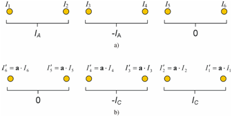
Instead of struggling with complicated impedance or admittance matrices and with the symmetrical three-phase current system IA, IB and IC (where IA, IB and IC are rms current phasors), let us connect the currents IA, –IA, and 0 on the conductors of Figure 2, just like Figure 3a shows. With this modified current system, the , , , ...complex currents will flow in conductors A1 … C2 respectively, where I1+I2=IA, I3+I4=-IA and I5+I6=0. The parameters A … F are the amplitudes of the currents, whereas α … ζ are the corresponding phase angles, and j is the imaginary unit. Now, connect the currents 0, –IC, IC on the conductors of Figure 2, as it appears in Figure 3b. It is easy to see that because of the planar symmetry, and since IC differs from IA only in a 120 degrees phase shift, the resulting current distribution will be similar to that of the previous example, only in opposite order and shifted by 120 degrees. In short, the currents , ... will flow in conductors A1 … C2 respectively, where the multiplication with represents a 120 degrees shift in time.
Finally, we have two current systems:
An attentive reader can easily recognize the relation between these two current systems and a balanced three-phase current system. By adding the currents in system 1 to the currents in system 2, the result is exactly a balanced three-phase current system. Our model is linear; therefore, we can exploit the principle of superposition, and obtain the currents of each individual elementary conductor with a balanced three-phase load by adding their currents in system 1 and 2. For instance, the current of conductor A1 is . In conductor C2 – which is the mirror image of A1 to the vertical symmetry plane a current of flows.
The idea of splitting up a balanced three-phase current system into two single-phase current systems for the ease of parametric calculations is not new. Tevan has used it in28 to determine the power-density distribution in 1D models of the enclosures of three-phase busbar systems. Because of the nature of those 1D models however, the distribution was always symmetric in his case.
The distribution of the time-average losses determining the steady-state temperature rise is symmetric, if the distribution of the rms current amplitudes is symmetric. In our simplified model: if the absolute values of the currents in the filamentary conductors symmetrical to each other are the same:
(3)
where α+δ=ζ. The angle δ indicates the phase shift between the currents of filaments A1 and C2 in both current systems. After reordering:
(4)
Simplifying by ejα, and converting the complex currents to their trigonometric forms:
(5)
By expressing the absolute values:
(6)
After simplifying:
(7)
By applying the trigonometric expression regarding the cosine of the sum of two angles:
(8)
and after simplifying:
(9)
Consequently, if the distribution is symmetric, δ can take the values of 0 or 180 degrees only. This is true for any elementary conductor pairs symmetrical to the vertical symmetry plane.
Finally, we can say that in order to have a symmetrical current distribution, the currents belonging to two elementary conductors symmetrical to each other must be in phase or exactly in opposing phase in any of the current systems 1 or 2. Consequently, we reduced the question of the complex asymmetric rms current-density distribution of balanced three-phase currents to the examination of only the phase shift between two elementary conductors in a system where the loading is single-phase, although asymmetric. In short: What condition has to be satisfied to have a phase-shift different from 0 or 180 degrees between the currents of conductors A1 and C2 with current system 1?
What a loss
We approach the problem with simple physical considerations. Since in current system 1, no net current flows in the conductor loop C1 – C2, the currents I5 and I6 are induced by the resultant of the magnetic fluxes Φ1 … Φ4. These fluxes are generated by the currents I1 … I4 of the other conductors. We note that – because of the electromagnetic proximity effect – the amplitudes of I1 and I2 belonging to IA are different. This holds for I3 and I4 belonging to –IA as well.29 If we removed the third loop from the model, namely if I5=I6=0 was satisfied, then the following would occur: I1 = –I4 and I2 = –I3. However, the induced currents I5 and I6 affect the inducing circuit; therefore, the previous equalities are not fulfilled. We only know for sure that I5 = –I6, namely the magnitudes of I5 and I6 are the same and they flow in opposite directions.
Anyway, the amplitudes are not interesting for us now; we need to examine only the phase shifts between the currents. In a general case, the phase shifts can also differ, even between the pairs I1 – I2 and I3 – I4. Let us see why. Start with a purely inductive circuit that is, we neglect the ohmic losses. Furthermore, we assume that IA and consequently –IA are real. First, we consider a single conductor pair (A1–A2) carrying a current of IA. If there is no other conductor carrying any other current in the proximity, then I1 = I2 = IA/2. Now, let us insert the right conductor pair (C1–C2) carrying no net current into the model. This conductor pair forms a loop, in which, according to Ampere’s law, the currents I1 and I2 create a magnetic flux Φ12, which is real. This magnetic flux varies sinusoidally, and induces a voltage in the loop: . It is clear that the phase shift between the induced voltage and the magnetic flux is 90 degrees. This voltage generates a current in the loop, which, in a purely inductive circuit, is also real:
(10)
Similarly, the currents I5 and I6 react on the exciting circuit I1 – I2, modifying the magnitude of I1 and I2, but not affecting their phase angles. The same phenomenon occurs between the loops I1–I2 and I3–I4, as well as between the loops I3–I4 and I5–I6. Consequently, all the currents remain real that is, the phase shift between the currents of any symmetrical conductor pairs (e.g. I1–I6) can be only 0 or 180 degrees as well. This means that the rms current amplitude distribution of the balanced three-phase ac system is symmetric in the elementary conductors if the system is purely inductive.
What is the matter with the ohmic resistance?
In a lossy circuit, the induced currents will have imaginary components too:
(11)
The back effect of these currents will shift the phases of the exciting currents. It is clear that finally the phase angles of the currents I1 … I6 are determined by the ratio of the mutual reactances and resistances. Several parameters affect these values, like the distances between the conductors and conductor loops, the resistivity, the frequency, etc. A change in any of these parameters results in different phase angles, the exact values of which – together with the amplitudes – can be calculated with the equation system mentioned above. However, we have every reason to believe that only in unique cases will they be 0 or 180 degrees in current systems 1 or 2. Therefore in a resistive ac system we can expect asymmetric loss distribution.
It is worthy of notice that a dc system, when ω=0, also results in symmetry.
Let the jurors judge
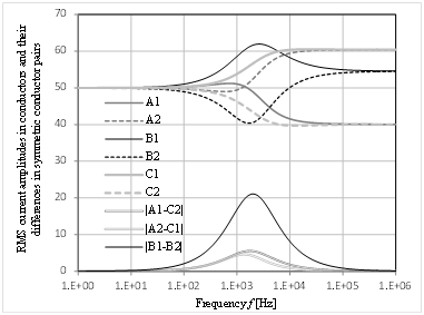
Now it is clear that the current density distribution and the time-average loss distribution are not necessarily symmetric in conductors arranged in a horizontal symmetry and loaded by a three-phase balanced current. The resistance of the conductors is responsible for the asymmetry. In solely inductive circuits, the phenomenon does not occur, explaining why asymmetry cannot be experienced in superconducting busbars with similar geometric configurations. Although at the beginning we excluded all numerical data from the proof, the correctness of our considerations can be testified by calculation examples. Let us solve the equations mentioned previously in section 3 for a simple configuration including the six elementary conductors of Figure 1b. Referring to the notation of the figure, let the parameters for our example be as follows: w=60mm, v=20mm, the radius of the solid conductors r=1mm, and the amplitude of the three-phase symmetric load current 100A, mA, or %. (Because of the linearity of the model, the magnitude and the unit of the current are not relevant here. Therefore the choice of 100% makes the evaluation of the results easier. This way, the currents of each conductor can be compared to the load current as a percentage.) Table 1 summarizes the currents distributed in the six conductors both for solely inductive and lossy circuits. In the latter case, the conductors were aluminum with a resistivity of ρ=3,36·10-8 Ωm. The frequency of the calculations was f=50Hz. By taking a closer look at the resulting currents, the symmetry is evident in the solely inductive circuit. However, the current distribution of the lossy conductors can hardly be called symmetric. It would be a bold idea to accuse rounding errors causing the differences in the currents in the latter case. It is worthy of notice that the sum of the resultant currents flowing in an elementary conductor pair forming one larger conductor is not equal to the load current. This implies a slight phase shift between the currents of the pairs. It is interesting that in this example, the difference is more noticeable in the purely inductive case. At first, some of the readers might think this fact contradicts a previous statement, namely that any of the currents must be in the same or opposing phase if the resistance is zero. There is no contradiction, since this statement holds true only for current systems 1 and 2 separately and not for their sum. It is interesting to see how the resistive or inductive character of the system influences the asymmetry. We have seen that the loss distribution was symmetric in solely inductive and dc circuits. If we fix the conductor resistances, these two extremes can be represented by f→∞ and f→0 respectively. Consequently, the easiest way to compare the differences is to change the frequency. The diagrams in Figure 4 show how the currents varied in our simple model as the frequency changed (the skin effect in the conductors was neglected even at high frequencies). It is clear that the 50 or 60 Hz of power distribution resulted only in a minor asymmetry. Maximum current–asymmetry in the symmetric conductor pairs A1–C2, A2–C1, and B1–B2 appeared at different frequencies between 1 and 2kHz.
|
|
IA |
|
IB |
|
IC |
|
Load current |
Real |
100 |
-50 |
-50 |
|||
Imaginary |
0 |
-86.6 |
86.6 |
||||
Resultant |
100 |
100 |
100 |
||||
|
|
IA1 |
IA2 |
IB1 |
IB2 |
IC1 |
IC2 |
Solely inductive circuit |
Real |
39.77 |
60.23 |
-43.87 |
-6.13 |
-25.94 |
-24.06 |
Imaginary |
-4.82 |
4.82 |
-32.41 |
-54.19 |
54.57 |
32.03 |
|
Resultant |
40.06 |
60.42 |
54.54 |
54.54 |
60.42 |
40.06 |
|
Lossy circuit |
Real |
50.15 |
49.85 |
-25.27 |
-24.73 |
-25.26 |
-24.74 |
Imaginary |
-0.22 |
0.22 |
-43.75 |
-42.85 |
43.34 |
43.26 |
|
|
Resultant |
50.15 |
49.85 |
50.53 |
49.47 |
50.16 |
49.84 |
Table 1 Numerical example to compare the current distributions of purely inductive and lossy circuits of Figure 1b.
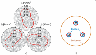
In short, even though the rms amplitudes of balanced three-phase currents are the same in all the three conductors, that is the time-average loads are symmetrically arranged, the resultant time-average power distribution is not necessarily symmetric. At least, not in the horizontal symmetry we have investigated. However, there are geometric arrangements, in which the current density distribution is symmetric even in lossy circuits. This is the case with Tevan’s28 theoretical 1D model mentioned above or with the busbars of high voltage GISs, where the circular conductors are situated in the vertices of an equilateral triangle within a circular enclosure (Figure 5b). Figure 5a represents this case, showing the current density distribution over the busbar surfaces in an Ir=3000 A switchgear.30 The distributions in each busbar are clearly identical but shifted by 120 degrees. Or only seemingly? Cannot the reason of the apparent symmetry hide within the limited resolution of the plot? Now, the sceptics could say that there can be tiny differences revealing themselves only with a higher magnification, not to mention that the similarity of surface distributions does not necessarily imply similarity over the entire cross section. These are all reasonable objections. For this case however, we let the reader prove the existence or the non-existence of the symmetry or refer to Arnold12 in this question.
None.
The author declares there is no conflicts of interest.

©2018 Novak. This is an open access article distributed under the terms of the, which permits unrestricted use, distribution, and build upon your work non-commercially.