Submit manuscript...
Advances in
eISSN: 2572-8490

Tissue Engineering & Regenerative Medicine: Open Access

Research Article Volume 3 Issue 3

Entropy production of composites with elliptical inclusions for bone analysi

Rodriguez-Lelis José María,1 Arellano-Cabrera José Antonio,3 Vargas-Treviño Marciano,2 Olivares-Peregrino Victor,1 Pérez-Ortega Joaquin,1 Rodriguez-Ramirez José Alfredo,4 Sáenz-Sánchez Socorro1

1Centro Nacional de Investigacion y Desarrollo Tecnológico, México
2Universidad Autónoma Benito Juárez de Oaxaca, México
3Equipos Médicos Vizcarra SA Circuito Industrial # 6, México
4Centro de Investigación en Ingeniería y Ciencias Aplicadas, Universidad Autónoma del Estado de Morelos, México

Correspondence: Rodriguez Lelis José María, Research Professor, Centro Nacional de Investigacion y Desarrollo Tecnológico, Cuernavaca, 62490, México

Received: August 01, 2017 | Published: December 6, 2017

Citation: María RLJ, Antonio ACJ, Marciano V, et al. Entropy production of composites with elliptical inclusions for bone analysis. Adv Tissue Eng Regen Med Open Access. 2017;3(3):368–373. DOI: 10.15406/atroa.2017.03.00063

Download PDF

Abstract

Mechanical behavior of composites, including biological tissue as bone, relates to its anisotropic condition and Young´s modulus distribution and stiffness through the individual contribution of its components. This could generally imply an elastic behavior and, from the energy point of view, that the energy is fully transmitted, in other words is conserved. However, the former statement is not completely true and entropy plays an important role. This implies for composite materials that energy and entropy are dependent on the geometrical arrangement geometry of the second phase. Bearing this in mind, in this work the Young´s modulus and the entropy generation of composite materials, with elliptical inclusions, under a compressive simple load is determined numerically. For the stress analysis, Eshelby´s tensor is employed for the boundary conditions and from here, the Young´s module is obtained from a finite element method. Entropy production is derived from Eshelby´s tensor and Hooke´s law too. The entropy is plotted in a polar diagram, and gives an indication of the capacity to absorb or dissipate energy as well as the directions in which energy is fully transmitted or not. On the other hand the Young’s modulus varies broadly from 10% to 30%, when the orientation of the elliptical inclusions varies from 90 to 0 degrees.

Keywords: entropy generation, composite, bone, young’s modulus, eshelby’s tensor

Introduction

The prediction of the effective mechanical behavior of composites is not always a problem with a straightforward solution. Generally, this has influences from the geometrical arrangement, shape and size of the composite aggregate. Several micromechanical methods can be found, where it is attempted to predict the effective properties of composite materials, among them are The Moriet al.,1 the self-consistent method,2,3 and the differential scheme.4

In the above-mentioned methods, the main objective is to find the average effective elastic properties of a composite. This consideration however, pays little attention to the independent particulate distribution and microstructure. Vieville et al.5 were concerned with the modeling of the effective properties of composite materials based on the inclusion concept. Starting from the kinematical integral equation for inhomogeneous materials, they reviewed and analyzed all principal homogenization methods. Special attention was focused on three approaches, namely the self-consistent scheme, the Mori-Tanaka method and incremental procedure derived from the differential scheme. Mono-site and multi-site versions of these approximate solutions were considered.

Sreedhar Kari et al.,6 evaluated the effective material properties of spherical particle reinforced composites for volume fractions up to 60%. A numerical homogenization technique based on the finite element method, with representative volume element, was used to evaluate the effective material properties with periodic boundary conditions. They propose that their method can be applied to any number of phases and there are no restriction regarding the number of materials, geometry and material symmetry and this can be used effectively to determine material coefficients of different types of fiber and particle reinforced composites. In addition, Gusev et al.7,8 experimented with randomly distributed short fiber composites and compared them with numerical results; he restricted his investigation to lower volume fractions of particles.

In biological materials, because of its composite nature, a number of attempts are to determine the global properties of the biological tissue. Cowin,9 proposed that the elastic properties of cancellous bone could be characterized as an orthotropic material, and thus by nine independent elastic constants to represent the dependence on bone volume fraction and trabecular architecture. He establishes that the constants can be determined by compression experiments or ultrasound measurements. These measurements are then related to bone volume fraction and measurements of trabecular architecture such as the MIL. Van Lenthe et al.10 carried a study, where a generic 2D model is proposed, and in which various trabecular bone structures were simulated and their corresponding Young’s modulus was calculated with finite element analysis.

A number of studies, where the main subject of study is to obtain a relation between the internal structure and anisotropic properties of composite materials, can be found in the literature. Hu et al.11 propose that when the size of reinforced particle is comparable to intrinsic length of matrix material, the nonlocal effect must be consider in a proper theoretical formulation. Sauer et al.12 developed an extension of a more general boundary condition, which allows for the continuity of both the displacement and traction field across the interface between a representative volume element and the surrounding composite. They obtain a new class of Eshelby tensors, which depend explicitly on the material properties of the composite and apply the new Eshelby tensors to the homogenization of composite materials, showing that several classical homogenization methods can be unified under a novel method termed the ‘Dual Eigenstrain Method’. Yin et al.13 investigated the mechanical properties of periodic composites containing identical spherical particles, and for this purpose, they employed the principles of micromechanics and homogenization procedures. They observed that the particle interactions did not contribute to the effective bulk modulus. A diversity of numerical analyses for predict the elastic properties of composite material are found in the literature.14–17 in general this works try to estimate the mechanical properties of composites as function of their materials concentration, size and type of reinforcements.

On the other hand, as described by Lakes18 a combination of stiffness and loss is desirable in damping layers and structural damping applications. For these applications, composite materials can give rise to such properties as a function of the distribution of the inclusions. Berdichevsky,19 conducted a study of the influence of entropy in determining the elastic properties of composite materials. He proposed two points of view:

  1. First, that energy of random structures is not determined uniquely by any finite set of the characteristics of microstructure and
  2. Information lost is characterized by entropy of microstructure and the entropy of microstructure can be found from the analysis of the homogenization problem. Bhadeshia et al.,20 developed a method to represent the degree of inhomogeneity in the primary microstructure of steels welds and related them to the toughness scatter. The method involved the calculation of "microstructural entropy", and they found that the microstructural entropy could directly be related with the degree of scatter observed in toughness data. Inhomogeneity and related material behavior have an interesting side to be explained through entropy and free energy, such as damage21 piezoelectric materials22,23 among other topics. An important concept can be drawn from these works, which could be related to the capacity to transmit stiffness or damping as a function of the entropy growth, and in consequence, to the potential for a change as a function of the free energy storage.

Following a similar line of work, the capability of a material to transmit a load o damp it, will be proportional to the amount of energy scattered, thus being also proportional to the entropy produced. Since entropy shows the direction of processes, its growth will be a function of the number of inclusions, geometrical arrangement and orientation of the inclusions, then can be envisage that as the entropy production decreases, the higher the work transmitted and stiffness will be; the opposite, as the entropy increases, the higher the work damped and the flexibility will be. Bearing this in mind, in this work, it is presented a numerical approach to evaluate the effect of Eshelby´s tensor on the entropy production of composite materials with symmetric distributions.

Materials and Methods

Micromechanical analysis of composites with inclusions involves the determination of contribution of three constituents, i.e. inclusions, matrix and inclusions-matrix interface. As described by 24, probably the single most referenced work in the extensive and rapidly growing literature on elastic composites is Eshelby´s 25 on the response of a single ellipsoidal elastic inclusion in an elastic whole space to a strain imposed at infinity. His results showed to be immensely useful in the analysis of composite materials, since most inclusion shapes commonly of interest can be approximated by some ellipsoid, particularly those linked to human bone tissue.

In the particular case of an elliptical inclusion embedded in an elastic and isotropic body, Eshelby 25 showed that the constraining strain ε c ij MathType@MTEF@5@5@+= feaagKart1ev2aaatCvAUfeBSjuyZL2yd9gzLbvyNv2CaerbuLwBLn hiov2DGi1BTfMBaeXatLxBI9gBaerbd9wDYLwzYbItLDharqqtubsr 4rNCHbGeaGqkY=xjYJH8sqFD0xXdHaVhbbf9v8qqaqFr0xc9pk0xbb a9q8WqFfeaY=biLkVcLq=JHqpepeea0=as0Fb9pgeaYRXxe9vr0=vr 0=vqpWqaaeaabiGaciaacaqabeaadaqaaqaaaOqaaKqzGeGaeqyTdu McdaahaaWcbeqcbasaaKqzadGaam4yaaaakmaaBaaajeaibaqcLbma caWGPbGaamOAaaWcbeaaaaa@4052@  can be calculated in terms of the transformation strain ε T ij MathType@MTEF@5@5@+= feaagKart1ev2aaatCvAUfeBSjuyZL2yd9gzLbvyNv2CaerbuLwBLn hiov2DGi1BTfMBaeXatLxBI9gBaerbd9wDYLwzYbItLDharqqtubsr 4rNCHbGeaGqkY=xjYJH8sqFD0xXdHaVhbbf9v8qqaqFr0xc9pk0xbb a9q8WqFfeaY=biLkVcLq=JHqpepeea0=as0Fb9pgeaYRXxe9vr0=vr 0=vqpWqaaeaabiGaciaacaqabeaadaqaaqaaaOqaaKqzGeGaeqyTdu McdaahaaWcbeqcKfay=haajugWaiaadsfaaaGcdaWgaaqcKfay=haa jugWaiaadMgacaWGQbaaleqaaaaa@4389@  from:

ε c ij = S ijkl ε kl T MathType@MTEF@5@5@+= feaagKart1ev2aaatCvAUfeBSjuyZL2yd9gzLbvyNv2CaerbuLwBLn hiov2DGi1BTfMBaeXatLxBI9gBaerbd9wDYLwzYbItLDharqqtubsr 4rNCHbGeaGqkY=xjYJH8sqFD0xXdHaVhbbf9v8qqaqFr0xc9pk0xbb a9q8WqFfeaY=biLkVcLq=JHqpepeea0=as0Fb9pgeaYRXxe9vr0=vr 0=vqpWqaaeaabiGaciaacaqabeaadaqaaqaaaOqaaKqzGeGaeqyTdu McdaahaaqcbawabKazba4=baqcLbmacaWGJbaaaOWaaSbaaKazba2= baqcLbmacaWGPbGaamOAaaqcbawabaqcLbsacqGH9aqpcaWGtbGcda WgaaqcKfaG=haajugWaiaadMgacaWGQbGaam4AaiaadYgaaKqaGfqa aKqzGeGaeqyTduMcdaqhaaqcKfaG=haajugWaiaadUgacaWGSbaajq waa+FaaKqzadGaamivaaaaaaa@59A3@  (1)

Here, S MathType@MTEF@5@5@+= feaagKart1ev2aaatCvAUfeBSjuyZL2yd9gzLbvyNv2CaerbuLwBLn hiov2DGi1BTfMBaeXatLxBI9gBaerbd9wDYLwzYbItLDharqqtubsr 4rNCHbGeaGqiVu0Je9sqqrpepC0xbbL8F4rqqrFfpeea0xe9Lq=Jc9 vqaqpepm0xbba9pwe9Q8fs0=yqaqpepae9pg0FirpepeKkFr0xfr=x fr=xb9adbaqaaeGaciGaaiaabeqaamaabaabaaGcbaqcLbsacaWGtb aaaa@375D@  refers to the Eshelby´s transformation tensor. This depends on the elastic properties of the inclusion´s material, its geometry and orientation 25. Then he showed that its solution could be adapted to find the field of an inclusion of different modulus under a uniform external stress.

Now, for a one dimensional lattice, Hookes law may be expressed by,

σ ij = C ijkl ε kl MathType@MTEF@5@5@+= feaagKart1ev2aaatCvAUfeBSjuyZL2yd9gzLbvyNv2CaerbuLwBLn hiov2DGi1BTfMBaeXatLxBI9gBaerbd9wDYLwzYbItLDharqqtubsr 4rNCHbGeaGqiVu0Je9sqqrpepC0xbbL8F4rqqrFfpeea0xe9Lq=Jc9 vqaqpepm0xbba9pwe9Q8fs0=yqaqpepae9pg0FirpepeKkFr0xfr=x fr=xb9adbaqaaeGaciGaaiaabeqaamaabaabaaGcbaqcLbsacqaHdp WCjuaGdaWgaaqcbasaaKqzadGaamyAaiaadQgaaSqabaqcLbsacqGH 9aqpcaWGdbqcfa4aaSbaaKqaGeaajugWaiaadMgacaWGQbGaam4Aai aadYgaaSqabaqcLbsacqaH1oqzjuaGdaWgaaqcbasaaKqzadGaam4A aiaadYgaaSqabaaaaa@4A8D@  (2)

where σ ij MathType@MTEF@5@5@+= feaagKart1ev2aaatCvAUfeBSjuyZL2yd9gzLbvyNv2CaerbuLwBLn hiov2DGi1BTfMBaeXatLxBI9gBaerbd9wDYLwzYbItLDharqqtubsr 4rNCHbGeaGqkY=xjYJH8sqFD0xXdHaVhbbf9v8qqaqFr0xc9pk0xbb a9q8WqFfeaY=biLkVcLq=JHqpepeea0=as0Fb9pgeaYRXxe9vr0=vr 0=vqpWqaaeaabiGaciaacaqabeaadaqaaqaaaOqaaKqzGeGaeq4Wdm NcdaWgaaqcbasaaKqzadGaamyAaiaadQgaaSqabaaaaa@3DF7@  refers to the stress field, C ijkl MathType@MTEF@5@5@+= feaagKart1ev2aaatCvAUfeBSjuyZL2yd9gzLbvyNv2CaerbuLwBLn hiov2DGi1BTfMBaeXatLxBI9gBaerbd9wDYLwzYbItLDharqqtubsr 4rNCHbGeaGqiVu0Je9sqqrpepC0xbbL8F4rqqrFfpeea0xe9Lq=Jc9 vqaqpepm0xbba9pwe9Q8fs0=yqaqpepae9pg0FirpepeKkFr0xfr=x fr=xb9adbaqaaeGaciGaaiaabeqaamaabaabaaGcbaqcLbsacaWGdb qcfa4aaSbaaKqaGeaajugWaiaadMgacaWGQbGaam4AaiaadYgaaSqa baaaaa@3D1D@ is the elastic properties tensor and ε kl MathType@MTEF@5@5@+= feaagKart1ev2aaatCvAUfeBSjuyZL2yd9gzLbvyNv2CaerbuLwBLn hiov2DGi1BTfMBaeXatLxBI9gBaerbd9wDYLwzYbItLDharqqtubsr 4rNCHbGeaGqiVu0Je9sqqrpepC0xbbL8F4rqqrFfpeea0xe9Lq=Jc9 vqaqpepm0xbba9pwe9Q8fs0=yqaqpepae9pg0FirpepeKkFr0xfr=x fr=xb9adbaqaaeGaciGaaiaabeqaamaabaabaaGcbaqcLbsacqaH1o qzjuaGdaWgaaqcbasaaKqzadGaam4AaiaadYgaaSqabaaaaa@3C1F@ is the second order tensor of elasticity. It follows that in order to expand the one-dimension model to bulk elastic behavior; it is required to sum all individual elastic deformations taken over all directions. Zhao & Yu 26, consider a composite consisting of a matrix and arbitrarily oriented inclusions in spheroid shape with different modulus embedded in the matrix. They proposed that the distribution of the inclusions is homogeneous and well separated, such that equation (2) could take the form:

σ ij = C ijkl r ε kl MathType@MTEF@5@5@+= feaagKart1ev2aaatCvAUfeBSjuyZL2yd9gzLbvyNv2CaerbuLwBLn hiov2DGi1BTfMBaeXatLxBI9gBaerbd9wDYLwzYbItLDharqqtubsr 4rNCHbGeaGqiVu0Je9sqqrpepC0xbbL8F4rqqrFfpeea0xe9Lq=Jc9 vqaqpepm0xbba9pwe9Q8fs0=yqaqpepae9pg0FirpepeKkFr0xfr=x fr=xb9adbaqaaeGaciGaaiaabeqaamaabaabaaGcbaqcLbsacqaHdp WCjuaGdaWgaaqcfasaaKqzadGaamyAaiaadQgaaKqbagqaaKqzGeGa eyypa0Jaam4qaKqbaoaaDaaajeaibaqcLbmacaWGPbGaamOAaiaadU gacaWGSbaajeaibaqcLbmacaWGYbaaaKqzGeGaeqyTduwcfa4aaSba aKqbGeaajugWaiaadUgacaWGSbaajuaGbeaaaaa@4DE0@  (3)

where C r MathType@MTEF@5@5@+= feaagKart1ev2aaatCvAUfeBSjuyZL2yd9gzLbvyNv2CaerbuLwBLn hiov2DGi1BTfMBaeXatLxBI9gBaerbd9wDYLwzYbItLDharqqtubsr 4rNCHbGeaGqkY=xjYJH8sqFD0xXdHaVhbbf9v8qqaqFr0xc9pk0xbb a9q8WqFfeaY=biLkVcLq=JHqpepeea0=as0Fb9pgeaYRXxe9vr0=vr 0=vqpWqaaeaabiGaciaacaqabeaadaqaaqaaaOqaaKqzGeGaam4qaO WaaWbaaSqabKqaGeaajugWaiaadkhaaaaaaa@3C17@ , is the elastic properties tensor of the composite. In accordance with Zhao 26, C r MathType@MTEF@5@5@+= feaagKart1ev2aaatCvAUfeBSjuyZL2yd9gzLbvyNv2CaerbuLwBLn hiov2DGi1BTfMBaeXatLxBI9gBaerbd9wDYLwzYbItLDharqqtubsr 4rNCHbGeaGqkY=xjYJH8sqFD0xXdHaVhbbf9v8qqaqFr0xc9pk0xbb a9q8WqFfeaY=biLkVcLq=JHqpepeea0=as0Fb9pgeaYRXxe9vr0=vr 0=vqpWqaaeaabiGaciaacaqabeaadaqaaqaaaOqaaKqzGeGaam4qaO WaaWbaaSqabKqaGeaajugWaiaadkhaaaaaaa@3C17@  for a two phase composite material and n inclusions is expressed by:

C r ijkl =[ r=0 n c n C ijkl f A ijkl ] [ r=0 n c n A ijkl ] 1 MathType@MTEF@5@5@+= feaagKart1ev2aaatCvAUfeBSjuyZL2yd9gzLbvyNv2CaerbuLwBLn hiov2DGi1BTfMBaeXatLxBI9gBaerbd9wDYLwzYbItLDharqqtubsr 4rNCHbGeaGqiVu0Je9sqqrpepC0xbbL8F4rqqrFfpeea0xe9Lq=Jc9 vqaqpepm0xbba9pwe9Q8fs0=yqaqpepae9pg0FirpepeKkFr0xfr=x fr=xb9adbaqaaeGaciGaaiaabeqaamaabaabaaGcbaqcLbsacaWGdb qcfa4aaWbaaSqabKqaGeaajugWaiaadkhaaaqcfa4aaSbaaKqaGeaa jugWaiaadMgacaWGQbGaam4AaiaadYgaaSqabaqcLbsacqGH9aqpju aGdaWadaGcbaqcfa4aaabCaOqaaKqzGeGaam4yaKqbaoaaBaaajeai baqcLbmacaWGUbaaleqaaKqzGeGaam4qaKqbaoaaDaaajeaibaqcLb macaWGPbGaamOAaiaadUgacaWGSbaajeaibaqcLbmacaWGMbaaaKqz GeGaamyqaKqbaoaaBaaajeaibaqcLbmacaWGPbGaamOAaiaadUgaca WGSbaaleqaaaqcbasaaKqzadGaamOCaiabg2da9iaaicdaaKqaGeaa jugWaiaad6gaaKqzGeGaeyyeIuoaaOGaay5waiaaw2faaKqbaoaadm aakeaajuaGdaaeWbGcbaqcLbsacaWGJbqcfa4aaSbaaKqaGeaajugW aiaad6gaaSqabaqcLbsacaWGbbqcfa4aaSbaaKqaGeaajugWaiaadM gacaWGQbGaam4AaiaadYgaaSqabaaajeaibaqcLbmacaWGYbGaeyyp a0JaaGimaaqcbasaaKqzadGaamOBaaqcLbsacqGHris5aaGccaGLBb Gaayzxaaqcfa4aaWbaaSqabKqaGeaajugWaiabgkHiTiaaigdaaaaa aa@7E97@  (4)

in which

A ijkl = I ijkl + S ijkl { [ ( C ijkl f C ijkl 0 ) S ijkl + C ijkl 0 ] 1 ( C ijkl 0 C ijkl f ) } MathType@MTEF@5@5@+= feaagKart1ev2aaatCvAUfeBSjuyZL2yd9gzLbvyNv2CaerbuLwBLn hiov2DGi1BTfMBaeXatLxBI9gBaerbd9wDYLwzYbItLDharqqtubsr 4rNCHbGeaGqiVu0Je9sqqrpepC0xbbL8F4rqqrFfpeea0xe9Lq=Jc9 vqaqpepm0xbba9pwe9Q8fs0=yqaqpepae9pg0FirpepeKkFr0xfr=x fr=xb9adbaqaaeGaciGaaiaabeqaamaabaabaaGcbaqcLbsacaWGbb qcfa4aaSbaaKazba4=baqcLbmacaWGPbGaamOAaiaadUgacaWGSbaa leqaaKqzGeGaeyypa0JaamysaKqbaoaaBaaajuaibaqcLbmacaWGPb GaamOAaiaadUgacaWGSbaajuaGbeaajugibiabgUcaRiaadofajuaG daWgaaqcfasaaKqzadGaamyAaiaadQgacaWGRbGaamiBaaqcfayaba WaaiWaaOqaaKqbaoaadmaakeaajuaGdaqadaGcbaqcLbsacaWGdbqc fa4aa0baaKqaGeaajugWaiaadMgacaWGQbGaam4AaiaadYgaaKqaGe aajugWaiaadAgaaaqcLbsacqGHsislcaWGdbqcfa4aa0baaKqaGeaa jugWaiaadMgacaWGQbGaam4AaiaadYgaaKqaGeaajugWaiaaicdaaa aakiaawIcacaGLPaaajugibiaadofajuaGdaWgaaqcfasaaKqzadGa amyAaiaadQgacaWGRbGaamiBaaqcfayabaqcLbsacqGHRaWkcaWGdb qcfa4aa0baaKqaGeaajugWaiaadMgacaWGQbGaam4AaiaadYgaaKqa GeaajugWaiaaicdaaaaakiaawUfacaGLDbaajuaGdaahaaWcbeqcba saaKqzadGaeyOeI0IaaGymaaaajuaGdaqadaGcbaqcLbsacaWGdbqc fa4aa0baaKqaGeaajugWaiaadMgacaWGQbGaam4AaiaadYgaaKqaGe aajugWaiaaicdaaaqcLbsacqGHsislcaWGdbqcfa4aa0baaKqaGeaa jugWaiaadMgacaWGQbGaam4AaiaadYgaaKqaGeaajugWaiaadAgaaa aakiaawIcacaGLPaaaaiaawUhacaGL9baaaaa@95DF@ (5)

where c n = V n /V MathType@MTEF@5@5@+= feaagKart1ev2aaatCvAUfeBSjuyZL2yd9gzLbvyNv2CaerbuLwBLn hiov2DGi1BTfMBaeXatLxBI9gBaerbd9wDYLwzYbItLDharqqtubsr 4rNCHbGeaGqiVu0Je9sqqrpepC0xbbL8F4rqqrFfpeea0xe9Lq=Jc9 vqaqpepm0xbba9pwe9Q8fs0=yqaqpepae9pg0FirpepeKkFr0xfr=x fr=xb9adbaqaaeGaciGaaiaabeqaamaabaabaaGcbaqcLbsacaWGJb qcfa4aaSbaaKqaGeaajugWaiaad6gaaSqabaqcLbsacqGH9aqpcaWG wbqcfa4aaSbaaKqaGeaajugWaiaad6gaaSqabaqcLbsacaGGVaGaam Ovaaaa@4204@ , I MathType@MTEF@5@5@+= feaagKart1ev2aaatCvAUfeBSjuyZL2yd9gzLbvyNv2CaerbuLwBLn hiov2DGi1BTfMBaeXatLxBI9gBaerbd9wDYLwzYbItLDharqqtubsr 4rNCHbGeaGqiVu0Je9sqqrpepC0xbbL8F4rqqrFfpeea0xe9Lq=Jc9 vqaqpepm0xbba9pwe9Q8fs0=yqaqpepae9pg0FirpepeKkFr0xfr=x fr=xb9adbaqaaeGaciGaaiaabeqaamaabaabaaGcbaqcLbsacaWGjb aaaa@3753@  is the fourth rank identity tensor and Sijkl is the Eshelby´s tensor. From here, it is readily noted that the young modulus will vary as a function of the inclusion´s geometry and position.

On the other hand, when a system undergoes a process, the energy spent during that process is transformed into work against its environment, either as heat or as other forms of energy in accordance with the first principle of thermodynamics. Then, as shown by Buryachenko 27 and considering only the work imposed by or against the system boundary, this energy may be:

dE=d W rev =dQ+ σ ij d ε ij MathType@MTEF@5@5@+= feaagKart1ev2aaatCvAUfeBSjuyZL2yd9gzLbvyNv2CaerbuLwBLn hiov2DGi1BTfMBaeXatLxBI9gBaerbd9wDYLwzYbItLDharqqtubsr 4rNCHbGeaGqkY=xjYJH8sqFD0xXdHaVhbbf9v8qqaqFr0xc9pk0xbb a9q8WqFfeaY=biLkVcLq=JHqpepeea0=as0Fb9pgeaYRXxe9vr0=vr 0=vqpWqaaeaabiGaciaacaqabeaadaqaaqaaaOqaaKqzGeGaamizai aadweacqGH9aqpcaWGKbGaam4vaOWaaSbaaKqaGeaajugWaiaadkha caWGLbGaamODaaWcbeaajugibiabg2da9iaadsgacaWGrbGaey4kaS Iaeq4WdmNcdaWgaaqcbasaaKqzadGaamyAaiaadQgaaSqabaqcLbsa caWGKbGaeqyTduMcdaWgaaqcbauaaKqzadGaamyAaiaadQgaaSqaba aaaa@51BF@  (6)

Equation (6) involves the full transformation, from one type of energy to the other. However, as expressed in general thermodynamics, it is required to add an amount of energy to complete the cycle. This amount is entropy 28:

dS= c p T dT+{ σ ij + ζ σ mm δ ij +α δ ij }d σ ij MathType@MTEF@5@5@+= feaagKart1ev2aaatCvAUfeBSjuyZL2yd9gzLbvyNv2CaerbdfgBPj MCPbqedmvETj2BSbqefm0B1jxALjhiov2DaerbuLwBLnhiov2DGi1B TfMBaebbnrfifHhDYfgasaacH8srps0lbbf9q8WrFfeuY=Hhbbf9v8 qqaqFr0xc9pk0xbba9q8WqFfea0=yr0RYxir=Jbba9q8aq0=yq=He9 q8qqQ8frFve9Fve9Ff0dmeaabaqaciGacaGaaeqabaWaaqaafaaake aajugibiaadsgacaWGtbGaeyypa0tcfa4aaSaaaOqaaKqzGeGaam4y aKqbaoaaBaaajeaibaqcLbmacaWGWbaaleqaaaGcbaqcLbsacaWGub aaaiaadsgacaWGubGaey4kaSscfa4aaiWaaOqaaKqzGeGafyicI4Sb auaacqaHdpWCjuaGdaWgaaqcbasaaKqzadGaamyAaiaadQgaaSqaba qcLbsacqGHRaWkcuaH2oGEgaqbaiabeo8aZLqbaoaaBaaajeaibaqc LbmacaWGTbGaamyBaaWcbeaajugibiabes7aKLqbaoaaBaaajeaiba qcLbmacaWGPbGaamOAaaWcbeaajugibiabgUcaRiabeg7aHjabes7a KLqbaoaaBaaajeaibaqcLbmacaWGPbGaamOAaaWcbeaaaOGaay5Eai aaw2haaKqzGeGaamizaiabeo8aZLqbaoaaBaaajeaibaqcLbmacaWG PbGaamOAaaWcbeaaaaa@6EE0@  (7)

where = 1 2 G MathType@MTEF@5@5@+= feaagKart1ev2aaatCvAUfeBSjuyZL2yd9gzLbvyNv2CaerbdfgBPj MCPbqedmvETj2BSbqefm0B1jxALjhiov2DaerbuLwBLnhiov2DGi1B TfMBaebbnrfifHhDYfgasaacH8srps0lbbf9q8WrFfeuY=Hhbbf9v8 qqaqFr0xc9pk0xbba9q8WqFfea0=yr0RYxir=Jbba9q8aq0=yq=He9 q8qqQ8frFve9Fve9Ff0dmeaabaqaciGacaGaaeqabaWaaqaafaaake aajugibiabgIGiolabg2da9KqbaoaalmaaleaajugibiaaigdaaSqa aKqzGeGaaGOmaaaacaWGhbaaaa@3FF7@ , ζ=ν/Y MathType@MTEF@5@5@+= feaagKart1ev2aaatCvAUfeBSjuyZL2yd9gzLbvyNv2CaerbuLwBLn hiov2DGi1BTfMBaeXatLxBI9gBaerbd9wDYLwzYbItLDharqqtubsr 4rNCHbGeaGqkY=xjYJH8sqFD0xXdHaVhbbf9v8qqaqFr0xc9pk0xbb a9q8WqFfeaY=biLkVcLq=JHqpepeea0=as0Fb9pgeaYRXxe9vr0=vr 0=vqpWqaaeaabiGaciaacaqabeaadaqaaqaaaOqaaKqzGeGaeqOTdO Naeyypa0JaeqyVd4Maai4laiaadMfaaaa@3ED5@ , δ MathType@MTEF@5@5@+= feaagKart1ev2aaatCvAUfeBSjuyZL2yd9gzLbvyNv2CaerbdfgBPj MCPbqedmvETj2BSbqefm0B1jxALjhiov2DaerbuLwBLnhiov2DGi1B TfMBaebbnrfifHhDYfgasaacH8srps0lbbf9q8WrFfeuY=Hhbbf9v8 qqaqFr0xc9pk0xbba9q8WqFfea0=yr0RYxir=Jbba9q8aq0=yq=He9 q8qqQ8frFve9Fve9Ff0dmeaabaqaciGacaGaaeqabaWaaqaafaaake aajugibiabes7aKbaa@3AFA@  = Kronecker´s delta, α MathType@MTEF@5@5@+= feaagKart1ev2aaatCvAUfeBSjuyZL2yd9gzLbvyNv2CaerbdfgBPj MCPbqedmvETj2BSbqefm0B1jxALjhiov2DaerbuLwBLnhiov2DGi1B TfMBaebbnrfifHhDYfgasaacH8srps0lbbf9q8WrFfeuY=Hhbbf9v8 qqaqFr0xc9pk0xbba9q8WqFfea0=yr0RYxir=Jbba9q8aq0=yq=He9 q8qqQ8frFve9Fve9Ff0dmeaabaqaciGacaGaaeqabaWaaqaafaaake aajugibiabeg7aHbaa@3AF4@  = expansion coefficient and C p MathType@MTEF@5@5@+= feaagKart1ev2aaatCvAUfeBSjuyZL2yd9gzLbvyNv2CaerbdfgBPj MCPbqedmvETj2BSbqefm0B1jxALjhiov2DaerbuLwBLnhiov2DGi1B TfMBaebbnrfifHhDYfgasaacH8srps0lbbf9q8WrFfeuY=Hhbbf9v8 qqaqFr0xc9pk0xbba9q8WqFfea0=yr0RYxir=Jbba9q8aq0=yq=He9 q8qqQ8frFve9Fve9Ff0dmeaabaqaciGacaGaaeqabaWaaqaafaaake aajugibiaadoeajuaGdaWgaaqcfasaaKqzadGaamiCaaqcfayabaaa aa@3DAB@  = specific heat; finally G and Y are the shear and Young’s modulus respectively, and v is Poisson´s ratio. Equation (7) determines the entropy field for isotropic materials. But if is considered an adiabatic system and composite material with N number of elliptical inclusions, the entropy production is expressed by:

S ijkl =α C ijkl 0 ε kl 0 +α n=1 N c n ( C ijkl f C ijkl 0 ) A ijkl ε kl 0 MathType@MTEF@5@5@+= feaagKart1ev2aaatCvAUfeBSjuyZL2yd9gzLbvyNv2CaerbuLwBLn hiov2DGi1BTfMBaeXatLxBI9gBaerbd9wDYLwzYbItLDharqqtubsr 4rNCHbGeaGqiVu0Je9sqqrpepC0xbbL8F4rqqrFfpeea0xe9Lq=Jc9 vqaqpepm0xbba9pwe9Q8fs0=yqaqpepae9pg0FirpepeKkFr0xfr=x fr=xb9adbaqaaeGaciGaaiaabeqaamaabaabaaGcbaqcLbsacaWGtb qcfa4aaSbaaKqbGeaajugWaiaadMgacaWGQbGaam4AaiaadYgaaKqb agqaaKqzGeGaeyypa0JaeqySdeMaam4qaKqbaoaaDaaajeaibaqcLb macaWGPbGaamOAaiaadUgacaWGSbaajeaibaqcLbmacaaIWaaaaKqz GeGaeqyTduwcfa4aa0baaKqaGeaajugWaiaadUgacaWGSbaajeaiba qcLbmacaaIWaaaaKqzGeGaey4kaSIaeqySdewcfa4aaabCaOqaaKqz GeGaam4yaKqbaoaaBaaajeaibaqcLbmacaWGUbaaleqaaKqbaoaabm aakeaajugibiaadoeajuaGdaqhaaqcbasaaKqzadGaamyAaiaadQga caWGRbGaamiBaaqcbasaaKqzadGaamOzaaaajugibiabgkHiTiaado eajuaGdaqhaaqcbasaaKqzadGaamyAaiaadQgacaWGRbGaamiBaaqc basaaKqzadGaaGimaaaaaOGaayjkaiaawMcaaKqzGeGaamyqaKqbao aaBaaajuaibaqcLbmacaWGPbGaamOAaiaadUgacaWGSbaajuaGbeaa jugibiabew7aLLqbaoaaDaaajeaqbaqcLbmacaWGRbGaamiBaaqcba saaKqzadGaaGimaaaaaKqaGeaajugWaiaad6gacqGH9aqpcaaIXaaa jeaibaqcLbmacaWGobaajugibiabggHiLdaaaa@8871@ (8)

Where C 0 ijkl MathType@MTEF@5@5@+= feaagKart1ev2aaatCvAUfeBSjuyZL2yd9gzLbvyNv2CaerbuLwBLn hiov2DGi1BTfMBaeXatLxBI9gBaerbd9wDYLwzYbItLDharqqtubsr 4rNCHbGeaGqiVu0Je9sqqrpepC0xbbL8F4rqqrFfpeea0xe9Lq=Jc9 vqaqpepm0xbba9pwe9Q8fs0=yqaqpepae9pg0FirpepeKkFr0xfr=x fr=xb9adbaqaaeGaciGaaiaabeqaamaabaabaaGcbaqcLbsacaWGdb qcfa4aaWbaaSqabKqaGeaajugWaiaaicdaaaqcfa4aaSbaaKqaGeaa jugWaiaadMgacaWGQbGaam4AaiaadYgaaSqabaaaaa@3FEA@  is the matrix’s elastic properties tensor, ε kl 0 MathType@MTEF@5@5@+= feaagKart1ev2aaatCvAUfeBSjuyZL2yd9gzLbvyNv2CaerbuLwBLn hiov2DGi1BTfMBaeXatLxBI9gBaerbd9wDYLwzYbItLDharqqtubsr 4rNCHbGeaGqiVu0Je9sqqrpepC0xbbL8F4rqqrFfpeea0xe9Lq=Jc9 vqaqpepm0xbba9pwe9Q8fs0=yqaqpepae9pg0FirpepeKkFr0xfr=x fr=xb9adbaqaaeGaciGaaiaabeqaamaabaabaaGcbaqcLbsacqaH1o qzjuaGdaqhaaqcKfaG=haajugWaiaadUgacaWGSbaajqwaa+FaaKqz adGaaGimaaaaaaa@41AD@ is the matrix strain; C ijkl f MathType@MTEF@5@5@+= feaagKart1ev2aaatCvAUfeBSjuyZL2yd9gzLbvyNv2CaerbuLwBLn hiov2DGi1BTfMBaeXatLxBI9gBaerbd9wDYLwzYbItLDharqqtubsr 4rNCHbGeaGqiVu0Je9sqqrpepC0xbbL8F4rqqrFfpeea0xe9Lq=Jc9 vqaqpepm0xbba9pwe9Q8fs0=yqaqpepae9pg0FirpepeKkFr0xfr=x fr=xb9adbaqaaeGaciGaaiaabeqaamaabaabaaGcbaqcLbsacaWGdb qcfa4aa0baaKqaGeaajugWaiaadMgacaWGQbGaam4AaiaadYgaaKqa GeaajugWaiaadAgaaaaaaa@3F56@ is the inclusion’s elastic properties tensor and A ijkl MathType@MTEF@5@5@+= feaagKart1ev2aaatCvAUfeBSjuyZL2yd9gzLbvyNv2CaerbuLwBLn hiov2DGi1BTfMBaeXatLxBI9gBaerbd9wDYLwzYbItLDharqqtubsr 4rNCHbGeaGqiVu0Je9sqqrpepC0xbbL8F4rqqrFfpeea0xe9Lq=Jc9 vqaqpepm0xbba9pwe9Q8fs0=yqaqpepae9pg0FirpepeKkFr0xfr=x fr=xb9adbaqaaeGaciGaaiaabeqaamaabaabaaGcbaqcLbsacaWGbb qcfa4aaSbaaKqaGeaajugWaiaadMgacaWGQbGaam4AaiaadYgaaSqa baaaaa@3D1B@ is the tensor who involve the elastic properties of the tow faces and the geometric, orientation and aspect ratio of inclusion.

As shown by Bejan 29, if one considers that the heat interaction with the environment varies as the work reaches a maximum, then it is found that the work transfer W, depends explicitly on the degree of the thermodynamic irreversibility of the system:

W= W rev To  S gen MathType@MTEF@5@5@+= feaagKart1ev2aaatCvAUfeBSjuyZL2yd9gzLbvyNv2CaerbuLwBLn hiov2DGi1BTfMBaeXatLxBI9gBaerbd9wDYLwzYbItLDharqqtubsr 4rNCHbGeaGqiVu0Je9sqqrpepC0xbbL8F4rqqrFfpeea0xe9Lq=Jc9 vqaqpepm0xbba9pwe9Q8fs0=yqaqpepae9pg0FirpepeKkFr0xfr=x fr=xb9adbaqaaeGaciGaaiaabeqaamaabaabaaGcbaqcLbsacaWGxb Gaeyypa0Jaam4vaKqbaoaaBaaajeaibaqcLbmacaWGYbGaamyzaiaa dAhaaSqabaqcLbsacqGHsislcaWGubGaam4BaabaaaaaaaaapeGaai iOaiaadofajuaGdaWgaaqcbasaaKqzadGaam4zaiaadwgacaWGUbaa leqaaaaa@4871@  (9)

In equation (9) the entropy rate production S gen MathType@MTEF@5@5@+= feaagKart1ev2aaatCvAUfeBSjuyZL2yd9gzLbvyNv2CaerbuLwBLn hiov2DGi1BTfMBaeXatLxBI9gBaerbd9wDYLwzYbItLDharqqtubsr 4rNCHbGeaGqiVu0Je9sqqrpepC0xbbL8F4rqqrFfpeea0xe9Lq=Jc9 vqaqpepm0xbba9pwe9Q8fs0=yqaqpepae9pg0FirpepeKkFr0xfr=x fr=xb9adbaqaaeGaciGaaiaabeqaamaabaabaaGcbaqcLbsaqaaaaa aaaaWdbiaadofajuaGdaWgaaqcbasaaKqzadGaam4zaiaadwgacaWG Ubaaleqaaaaa@3C58@  can never be negative, the term W rev MathType@MTEF@5@5@+= feaagKart1ev2aaatCvAUfeBSjuyZL2yd9gzLbvyNv2CaerbuLwBLn hiov2DGi1BTfMBaeXatLxBI9gBaerbd9wDYLwzYbItLDharqqtubsr 4rNCHbGeaGqiVu0Je9sqqrpepC0xbbL8F4rqqrFfpeea0xe9Lq=Jc9 vqaqpepm0xbba9pwe9Q8fs0=yqaqpepae9pg0FirpepeKkFr0xfr=x fr=xb9adbaqaaeGaciGaaiaabeqaamaabaabaaGcbaqcLbsacaWGxb qcfa4aaSbaaKqaGeaajugWaiaadkhacaWGLbGaamODaaWcbeaaaaa@3C4F@ then becomes the upper bound of W when the entropy becomes zero and the system operates reversibly. On the other hand, when work developed or transmitted by or through the system is zero. Also, considering from equation (6), that not heat is transferred back or forward the system by a cyclic process such as vibration. Then the work depends only on the stress, and strain directions. It may then be concluded that when a specific work ( σ ij MathType@MTEF@5@5@+= feaagKart1ev2aaatCvAUfeBSjuyZL2yd9gzLbvyNv2CaerbuLwBLn hiov2DGi1BTfMBaeXatLxBI9gBaerbd9wDYLwzYbItLDharqqtubsr 4rNCHbGeaGqiVu0Je9sqqrpepC0xbbL8F4rqqrFfpeea0xe9Lq=Jc9 vqaqpepm0xbba9pwe9Q8fs0=yqaqpepae9pg0FirpepeKkFr0xfr=x fr=xb9adbaqaaeGaciGaaiaabeqaamaabaabaaGcbaqcLbsacqaHdp WCjuaGdaWgaaqcbasaaKqzadGaamyAaiaadQgaaSqabaaaaa@3C37@ d ε ij MathType@MTEF@5@5@+= feaagKart1ev2aaatCvAUfeBSjuyZL2yd9gzLbvyNv2CaerbuLwBLn hiov2DGi1BTfMBaeXatLxBI9gBaerbd9wDYLwzYbItLDharqqtubsr 4rNCHbGeaGqiVu0Je9sqqrpepC0xbbL8F4rqqrFfpeea0xe9Lq=Jc9 vqaqpepm0xbba9pwe9Q8fs0=yqaqpepae9pg0FirpepeKkFr0xfr=x fr=xb9adbaqaaeGaciGaaiaabeqaamaabaabaaGcbaqcLbsacaWGKb GaeqyTduwcfa4aaSbaaKqaGeaajugWaiaadMgacaWGQbaaleqaaaaa @3D04@ ) is required in a specific direction, any other work directed in another direction will become damping, i.e., entropy production is intimately related to Young`s modulus and will vary in consequence as a function of the number and direction of the inclusions.

Preliminary results of the variation of the Young’s modulus in a composite material with elliptical inclusions were carried out by a 2D finite element analysis. The inclusions of elliptical geometry were embedded into a elastic matrix at different orientations. On the finite element analysis, it is considered the boundary, on the matrix-inclusion interface, as described by Eshelby 25. This consideration was taken in order to find out the strain field around an elliptical inclusion and its influence over the elastic matrix.

The models of composite materials proposed in this analysis, consider the following parameters:
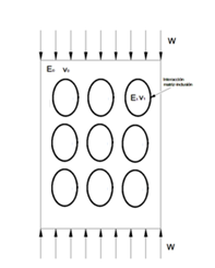
  1. The model geometry is rectangular in accordance with ASTM D 5024-01 norm for compression testing of materials.
  2. The material for the matrix was UHMWPE and the inclusions were elliptical voids with the same aspect ratio in all the models.
  3. The volume fraction for matrix and inclusion were 60 % and 40 % respectively and these percentages were constant for all the models. Figure 1 shows the discrete model of one of the models of composite material analyzed.

Figure 1 Discrete model of composite material model with elliptical inclusion and boundary conditions.

The composite material models undergo a compression load W in vertical direction and on the boundary, matrix-inclusion boundary conditions in accordance to Eshelby´s tensor were established 25. The elliptical inclusions were oriented from 0 to 90 degrees with respect to the compression load and their mayor axis as shown in Figure 2. Moreover, each inclusion rotates in steps of 10 degrees for the different models with the same compression load.

Figure 2 Rotation of inclusions within the matrix.

In the Figure 3 are shown that the inclusion arrangements that were evaluated. The first evaluation was carried out in an arrangement where the inclusions are placed one before the other and with a 90 degrees orientation. The second probe was arranged in such a way that the effect of odd sequence either in number and position could be assessed. The last probe, shown in Figure 3C, attempts to assess the effect of uneven rows.

Figure 3 Scheme of the three different internal architectures orientated at the 90°.

Results and discussion

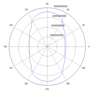
The values of the elasticity modulus obtained from the finite element analysis of models proposed are presented in a polar diagram in Figures 4 & 5. The polar diagram of Figure 4A shows the elasticity modulus corresponding to the model of Figure 3A. For this architecture, the elasticity modulus has a maximum for the orientation of inclusion at 90 degrees and as the angle reaches the 45 degrees, the elasticity modulus remains constant until the minimum value is achieved at zero degrees. Figure 4B shows the polar diagram where the number of inclusions varies horizontally and vertically. The maximum elasticity modulus is also located at 90 degrees but decreases with respect to the one shown in Figure 4A. The minimum value of the elasticity modulus, found at 0 degrees, also decreases but in a much smaller proportion.

Finally, the polar diagram of Figure 4C corresponds to the model presented in Figure 3C. Here, the inclusions are aligned vertically, but in the horizontal direction, the middle row is unevenly placed. The maximum and minimum values of elasticity modulus for the model 3c are similar to the values of model 3a but a waverly behavior is exhibited as the inclusions rotate from 90 to 0 degrees. On Table 1 are shown the differences of the elasticity modulus for the three models presented. From this table it can be seen that the larger elasticity modulus and in consequence stiffness is experience by the model of Figure 3C.

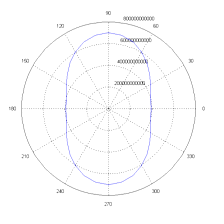
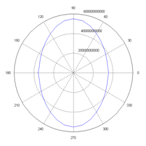
The polar diagrams of entropy production of the models described in the Figure 3 it is shown in Figure 5. The figure shows that exists a relationship between the elasticity modulus and entropy production generated of the composite material. In particular, Figure 5A shows the variation of entropy for the arrangement of Figure 3A and Elastic modulus of 4a. It can be seen from these graphs, that the maximum elastic modulus corresponds with the minimum value of entropy production and with the maximum stiffness.

Summarizing, the maximum entropy production is located at 0 degrees, where the elasticity modulus of the composite materials has the smallest value and in consequence the smallest stiffness (Table 2). Comparison between Figures 5A-5C shows that the smallest entropy production in either direction is exhibited by the arrangement of Figures 5A, although its behavior is similar. In addition, the maximum is experienced by the arrangement of Figures 5C at zero degrees.

On the other hand, as the elliptic inclusions are placed unevenly, the production of entropy in the polar graph has the tendency to form a circle, showing the capacity of the composite material to distribute and damp the load along the whole body. Now, considering equation (9), for a to constant, the lost work is proportional to the entropy generation. Thus, the largest lost work is shown by the model of Figures 3C, and described also by Figures 5C, which will be the largest damping or the largest probability of failure.
  • Figure 4 Polar diagrams of Young’s modulus obtained from the architectures proposed on figure 3a, 3b and 3c respectably.
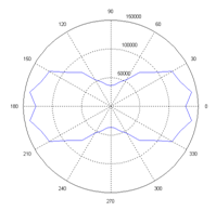
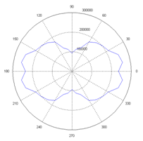
  • Figure 5 Polar diagrams of entropy generated from the architectures proposed on figure 3a, 3b and 3c respectably.

    Characteristics

    Orientation

    4

    9

    Model 3a

    Elasticity

    modulus

    3.90 GPa

    4.60 GPa

    7.00 GPa

    Model 3b

    3.58 GPa

    4.00 GPa

    5.60 GPa

    Model 3c

    3.69 GPa

    5.60 GPa

    7.20 GPa

    Table 1 Elasticity modulus variation of the proposed models for three inclusion orientation.

    Characteristics

    Orientation

    4

    9

    Model 4a

    Entropy Generation

    128 kJ/Kº

    95 kJ/Kº

    36 kJ/Kº

    Model 4b

    235 kJ/Kº

    205 kJ/Kº

    113 kJ/Kº

    Model 4c

    283 kJ/Kº

    183 kJ/Kº

    71 kJ/Kº

    Table 2 Entropy production as a function of orientation angle.

    Conclusion

    The results presented on this investigation suggest that in the composite materials with elliptic inclusions, the largest stiffness is obtained when the elliptical inclusions are oriented at 90 degrees and the largest damping is obtained at zero degrees. The polar diagrams showed that for each model the Young’s modulus varies broadly from 10% to 30%. In the particular case of Figure 3A the stiffness has a variation approximately of a 25% between its architecture at 0˚ and architecture at 90˚, and the general behavior describes an elliptical distribution of its young’s modulus.

    The polar diagrams of Figure 5 shows the entropy variation on the composite material and it is related with its mechanical behavior, hence the production of entropy change with the internal architecture of the material, and its ability to damp the loads applied to the body.

    Acknowledgements

    The present work was carried out under a project financed by Conacyt, No. 91019 and DGEST 2432.09-P -S.N.I. José Antonio Arellano Cabrera acknowledges the Mexican national science and technology bureau CONACyT for the awarded fellowship.

    Conflict of interest

    There is no financial or other conflict of interest.

    References

    1. Mori T, Tanaka K. Average stress in matrix and average elastic energy of materials with misfitting inclusions. Acta Metal. 197321(5):571–574.
    2. Hill R. A self-consistent mechanics of composite materials. J Mech Phys Sol. 1965;13(4):213–222.
    3. Budiansky B. On the elastic moduli of some heterogeneous materials. J Mech Phys Solids. 1965;13(4):223–227.
    4. McLaughlin R. A study of the differential scheme for composite materials. Int J Eng Sci. 1977;15(4):237–244.
    5. Vieville P, Bonnet AS, Lipiński P. Modeling effective properties of composite materials using the inclusion concept. General considerations. Arch Mech. 2006;58(3):207–239.
    6. Sreedhar Kari, Harald Berger, Reinaldo Rodriguez-Ramos, et al. Computational evaluation of effective material properties of composites reinforced by randomly distributed spherical particles. Composite Structures. 2007;77(2):223–231.
    7. Hine PJ, Lusti HR, Gusev AA. Numerical simulation of the effects of volume fraction, aspect ratio and fibre length distribution on the elastic and thermoelastic properties of short fibre composites. Compos Sci Tech. 2002;62(10-11):1445–1453.
    8. Lusti HR, Hine PJ, Gusev AA. Direct numerical predictions for the elastic and thermo elastic properties of short fibre composites. Compos Sci Tech. 2002;62(15):1927–1934.
    9. Cowin SC. The relationship between the elasticity tensor and the fabric tensor. Mechanics of Materials. 1985;4(2):137–147.
    10. Van Lenthe GH, Huiskes R. How morphology predicts mechanical properties of trabecular structures depends on intraspecimen trabecular thickness variations. J Biomech. 2002;35(9):1191–1197.
    11. Hu GK, Liu XN, Lu TJ. A variational method for nonlinear micropolar composite. Mech Mater. 2005;37(4):407–425.
    12. Sauer RA, Wang G, Li S. A circular inclusion in a finite domain I. The dirichlet-eshelby problem. Acta Mechanica. 2008;197(1-2):62–69.
    13. Yin HM, Sun LZ. Elastic modelling of periodic composites with particle interactions. Philosophical Magazine Letters. 2005;85(4):163–173.
    14. Huiyu Sun, Shenglin Di, Nong Zhang, et al. Micromecganics of composites materials using multivariable finite element method and homogenization theory. International Journal of Solid and Structures. 2001;38(17):3007–3020.
    15. Hyoung Seop Kim, Sun Ig Hong, Sun Jae Kim. On the rule of mixtures for predicting the mechanical properties of composites with homogeneously distributed soft and hard particles. Journal of Materials Processing Technology. 2001;112(1):109–113.
    16. Unnati A Joshi, Preeti Joshi, Harsha SP, et al. Evaluation of the mechanical properties of carbon nanotube based composite by finite element analysis. International Journal of Enginnering Science and Technology. 2010;2(5):1098–1107.
    17. Chunhui Yang, Hoon Huh, Thomas H Hahn. Evaluation of effective material properties of composite materials using special FEM. Journal of Materials Processing Technology. 2003;140(1-3):185–190.
    18. Lakes RS. High damping composite materials: effect of structural hierarchy. Journal of Composite Materials. 2002;36(3):287–297.
    19. Berdichevsky VL. Entropy of microstructure. Journal of the Mechanics and Physics of Solids. 2007;56(3):742–771.
    20. Sugden AAB, Bhadeshia HKDH. Microstructural entropy and the scatter in toughness. Recent Trends in Welding Science and Technology: 1989. p. 745–748.
    21. Cemal Basaran, Shihua Nie. A thermodynamics based damage mechanics model for particulate composites. International Journal of Solids and Structures. 2007;44(3-4):1099–1114.
    22. Yang Wei, Wang Hongtao, Cui Yuanqing. Composite Eshelby model and domain band geometries of ferroelectric ceramics. Science in China (Series E). 2001;44(4):403–413.
    23. Yozo Mikata. Explicit determination of piezoelectric Eshelby tensor for a spheroidal inclusion. International Journal of Solid and Structures. 2001;38(40-40):7045–7063.
    24. James G Berryman. Generalization of Eshelby's formula for a single ellipsoidal elastic inclusion to poroelasticity and thermoelasticity. Phys Rev Lett. 1997;79(6):1142–1145.
    25. Eshelby JD. The determination of the elastic field of an ellipsoidal inclusion and related problems. Proc Royal Soc of London Ser A. 1957;241(1226):376.
    26. Aihong Zhao, Jilin Yu. The overall elastic moduli of orthotropic composite and description of orthotropic damage of materials. International Journal of Solids and Structures. 2000;37(45):6755–6771.
    27. Valeriy A Buryachenko. Micromechanics of heterogeneous Materials. USA: Springer-Verlag; 2007. 687 p.
    28. Eshelby JD. Dislocations as a cause of mechanical damping in metals. Proc Roy Soc London A. 1949;197(1050):396–416.
    29. Bejan A. Entropy generation through heat and fluid flow. 2nd ed. New York, USA: McGraw-Hill; 1982.
    Creative Commons Attribution License

    ©2017 María, et al. This is an open access article distributed under the terms of the, which permits unrestricted use, distribution, and build upon your work non-commercially.