Advances in
eISSN: 2572-8490


Research Article Volume 7 Issue 1
1Centro Nacional de Investigación y Desarrollo Tecnológico, México
2Research and Development, Circuito Industrial # 6, México
3Universidad Autónoma del Estado de Morelos – CIICAp, México
Correspondence: Rodríguez-Lelis JM, Centro Nacional de Investigación y Desarrollo Tecnológico, Interior Internado Palmira s/n, Col. Palmira, Cuernavaca Morelos, México
Received: May 24, 2021 | Published: June 7, 2021
Citation: Rodríguez-Lelis JM, Arellano-Cabrera JA, Abúndez-Pliego A, et al. A numerical analysis of the contact stresses on surface of the femoral condyles of a knee prosthesis. Adv Tissue Eng Regen Med Open Access. 2021;7(1):28-33. DOI: 10.15406/atroa.2021.07.00124
A three-dimensional (3D) model to predict the contact stresses on the condylar surfaces of a knee prosthesis was developed. The contact stresses were evaluated, in accordance to the ISO 14243-1, at the 13% of gait cycle (15° flexion) and a normal load of 2500 N. This is the condition where it is assumed that the biggest loading occurs. Polyethylene elastic-plastic behavior was considered. The 3-D model was used to predict contact stresses occurring within the polyethylene insert, as the result of condyle surface stiffness, when a static pressure at a single instant was applied during the gait cycle. Results showed the contact stresses on the tibial insert are closely related to condyle surfaces stiffness.
Keywords: total knee replacement, finite element model, contact stresses
Early knee replacements design were mainly concern with joint functionality.1–3 Issues regarding stress distribution, contact stresses and wear were not an objective until 1970’s,4,5 and parameters such as geometry, mechanical properties of materials and surgery techniques became important to reduce wear and stress concentration.5 One of the first works related to the contact stresses was carried out by Ferguson,6 on the patella-femoral surfaces. Ferguson reliefed stresses by displacing the patella in order to modify the force directions. On the other hand, amongst the first works related to tissue reaction and bone destruction was that reported by Charnley.7 Based on those results, Charnley substituted Teflon by a low-friction arthroplasty made of high-density polyethylene (HDPE) and stainless steel. Later, Wroblewski8 carried out a histological study dealing with HDPE wear, debris shed into the joint cavity, and its effects on the failure of hip and knee joints. In the latter case, the excessive HDPE wear was assumed as a result of misalignment of the implant.8,9 Retrieval studies showed that the main cause of HDPE wear was the high contact stresses provided by very small contact areas, and the stress exceeds the yield strength of HDPE.10,11 In addition, laboratory tests showed that HPDE wear increased exponentially with increasing contact pressure,11 in turn, the latter increases if the articular surfaces of the implant are not conforming, if the PE is stiffer, or if the PE liner is not rigidly attached to the metal base-plate.12 Wear on total knee replacement TKR components occurs in three different mechanisms: adhesion, abrasion, and fatigue.13 All of them are associated, among other factors, to contact stresses on the components of the artificial joint. Several researches oriented to prevent the high rates of contact stresses have been carried out, including those that are oriented to determination of real joint loads,14 which depend both on physical activities and on body weight; 3-D dynamics body models15 and both knee joint and TKR Finite Elements Analysis (FEA).16,18 Here, a FEA is carried for four models: 1) commercial; 2) commercial with contact surface increased and 3) a coupling pair UHMWPE- UHMWPE and 4) a model with misfitting inclusions.
Model set up
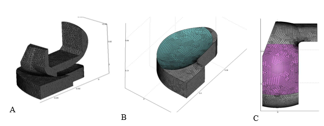
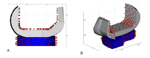
The geometry of the knee prosthesis was obtained from a domestic commercial model used in hospitals like the Mexican Institute of Health Services. Its geometry was obtained by coordinate measurement machine (CMM), and then rebuilt with 3D CAD software. Figure 1A shows the model of the total knee repkacement (TKR); where all minor geometry details such as chamfers, radii and back cavities were vanished in order to simplify the analysis. Like most of the femoral components currently in use in México, the material employed is a Cr – Cr – Mo alloy with a Young’s modulus of 210GPa and a Poisson ratio of 0.3.16 The tibial insert is made of UHMWPE which was assumed to behave as a nonlinear elastic – plastic material. Since TKR exhibits sagittal plane symmetry, it is possible to model only half of the geometry, as shown in Figure 1B. The TKR model was meshed with tetrahedral type elements as shown in figure 2. Refinement was carried out on the condyle and tibial insert contact surfaces, highlighted in Figure 2A & 2B, respectively. The highlighted surfaces in Figure 2B & 2C were placed in prescribed contact and the components were aligned according the position of maximum load reported in the ISO 14243-1. All of the four models were computed having identical alignment, loads, constraints and boundary conditions. Figure 3 shows the lateral a) and isometric b) views of the cloading and boundary conditions. The whole interior surface of the femoral component was constrained as roller, while the tibial insert was constrained to allow motion only in the vertical direction. The inferior surface of the tibial insert was loaded with a uniform pressure with a resultant of 1.1kN in the positive vertical direction, so the displacement by loads occurred only in the tibial insert. Four models were solved; 1) commercial; 2) commercial with more compliant contact surfaces and 3) a coupling pair UHMWPE- UHMWPE and 4) a model with misfitting inclusions, forming a composite material, where the surface stiffness and overall elastic properties are closely related to size, orientation and density of the inclusions.19–23

Figure 2 Meshing of the TKR model: A) Half model, B) Tibial component contact surface and C) Femoral component contact surface.

Figure 3 Loads, constraints and boundary conditions for A) longitudinal cross section and B) isometric FEM model.
Composites Mathematical Modeling
Micromechanical analysis of composites with inclusions involves the determination of contribution of three constituents, i.e. inclusions, matrix and inclusions-matrix interface. As described by,24 probably the single most referenced work in the extensive and rapidly growing literature on elastic composites is Eshelby´s paper20 on the response of a single ellipsoidal elastic inclusion in an elastic whole space to a strain imposed at infinity. His results showed to be immensely useful in the analysis of composite materials, since most inclusion shapes commonly of interest can be approximated by some ellipsoid, particularly those linked to human bone tissue. In the particular case of an elliptical inclusion embedded in an elastic and isotropic body, Eshelby20 showed that the constraining strain εCij can be calculated in terms of the transformation strain εCij from:
(1)
Here, S refers to the Eshelby´s transformation tensor. This depends on the elastic properties of the inclusion´s material, its geometry and orientation.20 Then he showed that its solution could be adapted to find the field of an inclusion of different modulus under a uniform external stress. Now, for a one dimensional lattice, Hookes law may be expressed by,
(2)
where σij refers to the stress field, Cijkl is the elastic properties tensor and εkl is the second order tensor of elasticity. It follows that in order to expand the one-dimension model to bulk elastic behavior; it is required to sum all individual elastic deformations taken over all directions. Zhao & Yu25 consider a composite consisting of a matrix and arbitrarily oriented inclusions in spheroid shape with different modulus embedded in the matrix. They proposed that the distribution of the inclusions should be considered homogeneous and well separated, such that equation (2) could take the form:
(3)
where Cr, is the elastic properties tensor of the composite. In accordance with Zhao, Cr for a two phase composite material and n inclusions is expressed by:
(4)
in which
(5)
Where cn=Vn/V, I is the fourth rank identity tensor and Sijkl is the Eshelby´s tensor. From here, it is readily noted that the young modulus will vary as a function of the inclusion´s geometry and position.
Figure 4 shows the Von Misses stresses for the TKR commercial model. In this figure are shown the maximum contact stresses experienced in one of the nodes of the mesh arrangement. These are in the case of the femoral component: 180, 162, 120 and 34MPa; and for the tibial component: 121, 174, 36 and 25MPa. Considering now the pair Vitalium-UHMWPE as shown in figure 4A, it may be seen that the stresses around 70 to 121 on the tibial component are concentrated in small areas, which will indeed over a period of time will be nucleation centers for wear and fracture. However the larger area experienced stresses between 40 and 60MPa, which are within the limits of the yielding stress of the UHMWPE. In the second model depicted on figure 4B the geometry of the tibial insert was slightly modified to obtain an improved conformal contact and increase of the contact surface. As a result of these changes, contact surface increased by 5 percent and contact stresses in the femoral component decreased by 10 percent. However, results for this model exhibited higher stresses on UHMWPE tibial component, from 174 to 110 around the change of curvature of the tibial component which will cause its failure. In contrast with regards to the UHMWPE - UHMWPE prosthesis shown in Figure 4C & 4D, the contact stresses are considerably smaller than those of the metallic femoral component. The largest stress is found in the femoral component with a numerical value around the 80MPa. For the tibial component the stresses are close to the 35MPa. The maximum stresses distribution is similar to the Vitalium- UHMWPE prosthesis because both are considered completely solid. Finally the model shown in Figure 4D where misffiting inclusions were introduced, the maximum contact stresses found were of the order of 15Mpa. This is attributed to the effect of the inclusion.19–23
Analysis described in this paper can be divided into two parts. The first part contains models with both materials and geometry used currently in Mexican Hospitals, and whose results are shown in Figures 4A & 4B. In these models was shown that contact stresses on the UHMWPE surface were higher than yield strength (20–25MPa), and much higher than permissible stress. Although a modification was introduced on the external geometry in the latter model, modification that helped to decrease contact stresses on surfaces of both prosthesis components, it was not enough to reach an acceptable range. In fact, results of the Finite Element Analysis demonstrated that surface bears the whole load between both bodies. In the second part of the analysis two models were solved by finite element using UHMWPE in both the femoral and tibial components, as shown in Figures 4C & 4D. Both models have identical external geometry, but the second one has misffiting inclusion in the internal architecture in the femoral component of the knee prosthesis. In fact, changes were made only in femoral component in order to demonstrate the influence of its mechanical properties on the stress distribution of the tibial insert surface.
It is shown that geometry, components material among others factors do affect contact stresses on TKR surfaces, but the stiffness of the femoral component surface must be an essential factor to be considered for designing new replacements. FEM models solved showed that appropriate internal architecture of the components can shift contact stresses into the body and diffuses them far from the surface, without compromising the surfaces integrity.
None.
The authors declare that there is no conflict of interest.

©2021 Rodríguez-Lelis, et al. This is an open access article distributed under the terms of the, which permits unrestricted use, distribution, and build upon your work non-commercially.