eISSN: 2576-4500


Research Article Volume 6 Issue 4
Chair of geophysics, Azerbaijan State University of Oil and Industry, Azerbaijan
Correspondence: Tofiq R Akhmedov, Doctorate in geology and mineralogy, Professor at the Chair of geophysics, Azerbaijan State University of Oil and Industry, Azadliq Avenue 20, Baku, Azerbaijan
Received: September 17, 2022 | Published: October 6, 2022
Citation: Akhmedov TR, Mammadova AM, Mammadov RJ. The influence of curvilinear form of boundaries on reflected wave field. Aeron Aero Open Access J. 2022;6(4):160-164. DOI: 10.15406/aaoaj.2022.06.00156
The paper is devoted to the influence of curvilinear reflection boundaries on kinematic and dynamic 1haracteristics of reflected seismic waves. First of all, the paper describes the major reasons of low geological efficiency of CDP seismic survey in the areas of Azerbaijan, characterized by complex surface and deep seismic and geological environmental features and in this aspect, the special attention is paid to curvilinear boundaries. The paper displays statistical data for Shamakhy-Gobustan province, where of 132 anticlinal folds only a few are under production currently.
It is considered, how the spatial curvilinear nature of reflection surfaces influence reflection waves propagation. In addition, by use of 3D seismic data the formula is given for breakdown of reflection waves along propagation planes in space. As the example, VSP data from a well in Absheron peninsula are displayed and on the seismic records, it is possible to clearly observe the out of plane waves, which do not propagate in the section plane (in the vertical plane).
Velocity analysis is based on evaluation of coherency measure, which allow to assess the correlation level of reference point of seismic traces in the given time window along the hyperbolic trajectory of curvature depending on time and velocity. It is known that in case of curvilinear reflection boundaries the observed travel time graphs are far from hyperbolic by their shape, and due to this, in the process of velocity analysis we derive both optimal stacks, which are the subject to the rule of velocity change versus time, common to this area, and also quite different stacks, which we name as “anomalous”. The great importance is to make clear the nature of these “anomalous” stacks at the initial stage of study as they keep some hidden information about the geology of the area. Analysis display that in addition to folded reflections, the cause of these anomalous stacks may be the curvilinear boundaries, horizontal gradient of the velocity. Curvilinear boundaries influence also the dynamic parameters, wave amplitudes in particular, as in the case of curvilinear boundaries the seismic rays are focusing due to the concaved shape of boundary. It has been noted that if the curvature of a syncline form boundary is not constant, then at the defined reception points the reflections arrive from several parts (points) of syncline and the reflected energy will be recorded as several branches (most frequently as three). As the light is focused when it passes through the lens, the seismic waves are similarly focused by curvilinear boundaries and due to the refraction the seismic rays are bended and we observe intensive reflections on seismic sections.
Keywords: oil, gas deposits, CDP seismic survey, lateral waves (out of plane waves), curvilinear boundaries, velocity analysis, dynamic parameters
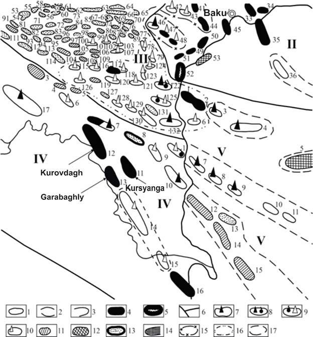
Azerbaijan is rich by oil and gas deposits, with some of them situated in Absheron oil and gas province and exploited for centuries, while the others are located in the West Absheron, Shamakhy-Gobystan province, etc. and still are waiting for their turn. It must be noted that only a few fields have been discovered in these oil and gas provinces.1 The reason is the low geological efficiency of seismic survey caused by complicated surface and deep geological environment, featured by presence of narrow dish-shaped synclines with curvilinear and steep dip angles of flanks. It can be seen from a map in Figure 1, that 132 perspective structures are observed in Shamakhy-Gobystan oil and gas area, and only a few of them are under production.2 Obviously, surface geological environment play a certain role here, and in addition, the task of study of geological setting here is three-dimensional. The studied oil and gas province is characterized by presence of narrow bowl-shaped synclines with steep angles of dip at the flanks. This seriously complicates the seismic survey, decreasing geological efficiency of these works. In this paper, we will consider some tasks related to the influence of curvilinear boundaries on kinematic and dynamic characteristics of reflected waves.

Figure 1 Map of oil-bearing and perspective areas of Azerbaijan.
(Extraction from a map)6
1 – anticlinal structures; 2 – monoclinal structures; 3 – structural terraces and structural noses; 4 – oil fields under development; 5 – gas condensate and oil fields under development; 6 – boundaries of oil and gas areas; 7 – areas covered by exploration drilling; 8 – areas, currently covered by exploration drilling and produced commercial oil and gas flows; 9 – areas, previously covered by exploration drilling and produced commercial oil and gas flows; 10 – areas covered by exploration drilling; 11 – areas covered by structural-appraisal drilling; 12 – areas, covered by geological survey and mapping drilling from the vessel; 13 – structures discovered by in-field geophysical survey; 14 – areas and zones with oil and gas perspectives tied to Mesozoic; 15 –areas and zones with perspectives tied to Oligocene and Miocene ages; 16 –areas and zones, in which oil and gas perspectives are tied to the Pliocene;6
II – Absheron province: 33 – Garachukhur-Zykh; 34 – Hovsan; 35 – Qum-adasy; 36 – Makarenko bank; 42 – Karaeybat (Damlamaja); 43 – Kobi-Shabandagh; 44 – Atashgyah (Shubany); 45 – Bibieybat-Ilyich bukhtasi; 46 – Shorbulag; 47 – Sarynja-Gulbakht; 48 – Shongar; 49 – Puta; 50 – Lokbatan; 51 – Kergez-Qyzyltepe; 52 – Garadagh; 53 – Lokbatan-more
III – Shamakhy-Gobystan province: 53 – Leninabad; 54 – Mirzangal; 55 – Teklya; 56 – Jagyrli; 57 – Kalidjan; 58 – South Ahudagh; 59 – South Shimshadi; 60 – Maraza; 61 – Qurbanchi (Arabshahverdi); 62 – Sygyrkechmeg; 63 – Jangi; 64 – Dostibozy; 65 – Gultamin (Babajan); 66 – South Jangi; 67, 68 – South Sungur-Kuturtash; 69 – Alakishlak; 70 – Buransyz-Boyanata; 71 – Khydyrly; 72 – Kazeydagh; 73 – Gaiblyar-Shaiblyar; 74 – Baygushty; 75 – Kalagjalyar; 76 – Kirdagh; 77 – Kirkyshlak; 78 – Shykhykaya; 79 – Anart; 81 – Chyrakhly; 82 – Adjidere; 83 – Ukakhana; 84 – Shykhzagirli; 85 – Burgyut; 86 – Donguzdyk; 87 – Kargabazar; 88 – Kaftaran; 89 – Agzykyr; 91 – Matrasa; 93 – Karamanly; 94 – Paladly; 95 – Yavandagh; 96 – Shorsuli; 97 – Hijaki; 98 – Juan; 99 – Sheytanud; 100 – Hijakiakhtarma; 101 – Nardaranakhtarma; 102 – Suleyman; 103 – Cheilakhtarma; 104 – Qarbi Sundi; 105 – Shargi Sundi; 106 – Kurdamich (Neftik); 107 – Cheildagh; 108 – Ilkhichi; 109 – Zagirdagh; 111 – Geglyar; 112 – Kushchi; 113 – Girda; 114 – Gungermez (Uduli); 115 – West Ajiveli; 116 – Ajiveli; 117 – Umbaki; 118 – Rahim; 119 – Shokikhan; 120 – Arzaniklych; 121 – Touragay; 122 – Kyanizadagh; 123 – Utalghi; 124 – Miajik; 125 – Duvanniy-Kichik Kyanizdagh; 126 – Dashmardan; 127 – Baridash; 128 – Salakhay; 129 – Ayrantekan; 130 – Koturdagh; 131 – Kirdagh (Gegyarchin); 132 - Dashgil
IV – Prikurinsk area: 1 – Pirsaat; 3 – Kalamaddin; 4 – Boyuk Harami; 5 – Kyrlykh; 6 – Kichik Harami; 7 – Mishovdagh; 8 – Qalmas; 9 – Khydyrly; 10 – Byandovan; 11 – Kursyanga; 12 – Kurovdagh; 13 – Garabaghly; 14 – Babazanan-Durovdagh; 15 – Khylly; 16 – Neftchala; 17 – Padar
V – Baku archipelago: 1 – Sangachal-deniz; 2 – Duvanniy island; 3 – Bulla island; 4 – Bulla-deniz; 5 – Andreyev bank; 6 – Alyat-deniz; 7 – Khamamdagh-deniz; 8 – Svinoy-more; 9 – Persianin bank; 10 – Kamen Ignatiya; 11 – Kornilov-Pavlov bank; 12 – Byandovan-deniz; 13 – Kumani bank; 14 – Pogorelaya Plita bank; 15 – Golovacheva bank; 16 – Karagedova bank.6
Let us consider the influence of spatial curvilinear shape of reflection boundaries on propagation of reflection waves. Reflection waves, which are recorded over the bowl-shaped synclines, are propagating in various directions in space and most of them reach the observation points in planes dipped under various angles and their position in space are defined by the following expression:
These expressions establish relationship between the elements of burial of reflection surfaces (j,y) and parameters of planes of reflection waves in space (eр, aр) and the azimuth of aр observation line. Here, j and y are respectively the dip angle and azimuth of downdip-updip line of reflection surface, eр is the angle between the vertical plane of the section and the plane of propagation of reflection waves,
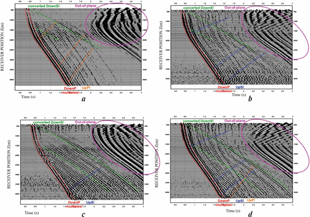
3D nature of the problems, facing seismic survey is well-demonstrated by Vertical Seismic Profiling (VSP), as by three components of fluctuations (vertical Z, horizontal X and Y), and also by polarization component HMX it is possible to clearly observe the converted incident S-wave (Down S), refracted multiple P-wave (Down P) and reflection P-wave (UpP), out of plane lateral waves, incident and reflected S-waves (Down S/ UpS) (Figure 2).

Figure 2 VSP time sections from well 1856 in Hovsan field of Azerbaijan: in sections by three components of fluctuations (vertical Z (a), horizontal X (b) and Y(c), and also by polarization component HMX (d).
It must be noted, that on these VSP time sections, the lateral waves with characteristic wave patterns distinguishing from the basic part of seismic record are clearly observed. Obviously, the lateral waves are present also on surface seismic observations, however they do not display themselves on seismic records, interfering with reflection waves propagating in the vertical plane of section and creating complicated wave image, which is difficult to interpret.
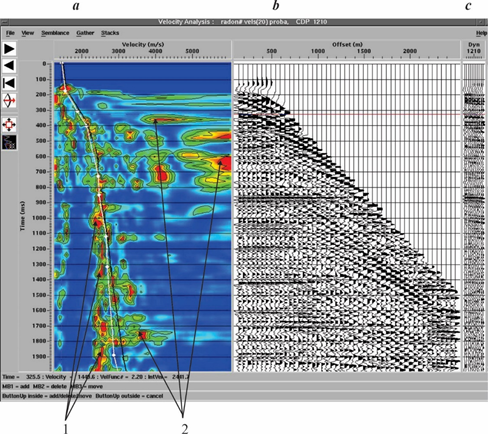
Seismic data processing applies many techniques for wave velocity evaluations and of these the dominating role belongs to the techniques based on use of regulated directional analysis of the wave field with evaluation of effective velocity or normal increment of time, corresponding to direction of maximum coherency or energy of the field (optimization of the stacking). Tools based on optimization of stacking are known in practice as the tools for velocity analysis done by deriving the spectrum of velocities for various parts of observation line. Velocity analysis is based on evaluation of coherency measure, which allows to evaluate the level of correlation of seismic traces in the given time window along the hyperbolic trajectory of testing curvature, which depends on time and velocity.1,2 It is known, that in case of curvilinear reflecting boundaries the observed traveltime graph by its shape is far from hyperbolic, therefore in the process of velocity analysis we derive both optimal stacks subjected to the rule common for this study area, and quite different stacks, which we have named as “anomalous”. Field of optimal stacks acquired while velocity analysis, can be divided in two parts by velocity curve, adopted for calculation of kinematic corrections (Figure 3).

Figure 3 Optimal stacks, derived at anomalous low (1) and high (2) velocity values: а – velocity range; b, c – seismic records prior and after applying kinematic corrections.
In general, geophysics are satisfied by attributing the stacks acquired for anomalously low velocity values to the many-fold waves and do not investigate the nature of other type of stacks (acquired at the high velocity rates).3 In our opinion, making clear the nature of “anomalous” stacks is of a large practical interest at the initial stage of study of geological section as they hold the hidden information about the studied geological environment. Analysis display that along with many-fold reflections, the reason of these anomalous stacks may include the curvilinear shape of boundaries, horizontal gradient of velocity, diffracted waves, etc. It has been indicated earlier, that if the reflection boundary is continuous and flat, the each reflection point corresponds to the point of travel time graph and the travel time graph does not have the special node points and return points. The clear correspondence exists between reflection points and points on the traveltime graph. It is known, that no such correspondence exists for curvilinear boundaries, and the traveltime graph has very complex form with node points and return points.4
Curvilinear nature of boundary influences also the dynamic parameters, such as wave amplitude, as due to the curvilinear feature of a boundary in case of concave-shaped boundary the seismic rays are focusing. If in the environment with a constant velocity the elastic wave excitation is done by point source, the seismic wave directed to the depth of the environment has a spherical wave front, which radius is equal to the distance from the source.5 Let us suppose that such a wave falls on the boundary of the spherical form with radius of curvature as and the curvature center is directly under the source. R.Sheriff, L.Geldart in their classical work6 used the known formula for geometrical optics for the distorted mirror:
Where - the distance between the mirror and the target; - the distance from the reflection of the target in the mirror up to the mirror itself; R radius of the curvature of the mirror. Positive value of R corresponds to the concaved mirror, negative value corresponds to the true (real) reflection.7
Practically all interesting cases of curvilinear boundaries have been considered in this classical work, so we will not review them in detail and recommend all those interested to refer to this source work.8 If the curvature of a syncline shape boundary is not constant, then at definite reception points the reflections arrive from several parts (points) of syncline and reflected energy will be written in form of several branches (generally, three branches).9 Similar to that, as the light is focusing while passing through the lens, seismic waves are also focused by curvilinear boundaries and due to the refraction the seismic waves are bending and the intensive reflections are observed on seismic sections (Figure 4).10
The curvilinear nature of the bottom of low velocity zone gains a special value as the sharp velocity changes are related to this boundary.11
The curvilinearity of the reflecting boundaries leads to the spatial multidirectionality of the reflecting surfaces, which affects the observed seismic wave field, since the waves reflected from the spatially multidirectional surfaces, superimposed on each other, interfere with each other and create a very complex wave pattern that cannot be unambiguously interpretation. The results of velocity analysis are also affected by the curvilinearity of the boundaries: in the vertical velocity spectrum, several maximum sums are obtained at the same time.12
The amplitudes of the reflected waves change due to the curvilinearity of the boundaries, the waves formed in different parts of the synclinal boundary will be focused, creating anomalously intense reflections.
None.
The Authors declares that there is no Conflict of interest.

©2022 Akhmedov, et al. This is an open access article distributed under the terms of the, which permits unrestricted use, distribution, and build upon your work non-commercially.