
Research Article Volume 2 Issue 2
Design and analysis of a dual reaction wheel with ultrasonic motor for nano-satellites
Xun Sun, Xiaofeng Wu
Regret for the inconvenience: we are taking measures to prevent fraudulent form submissions by extractors and page crawlers. Please type the correct Captcha word to see email ID.

School of Aerospace, University of Sydney, Australia
Correspondence: Xiaofeng Wu, School of Aerospace, Mechanical, and Mechatronics Engineering, University of Sydney, NSW 2006, Australia
Received: March 03, 2018 | Published: April 27, 2018
Citation: Sun X, Wu X. Design and analysis of a dual reaction wheel with ultrasonic motor for nano-satellites. Aeron Aero Open Access J. 2018;2(2):98-103. DOI: 10.15406/aaoaj.2018.02.00038
Download PDF
Abstract
This paper introduces the design of a dual actuator nano reaction wheel system for the 3U CubeSat AMMEQ-1. AMMEQ-1 is a joint research project between the University of Sydney, Australia and the Centre for Quantum Technologies, National University of Singapore. The primary mission of this project is to demonstrate technologies for the future Quantum Key Distribution (QKD) payload for secure communications1). In this reaction wheel design project, a dual actuator system is designed by combining an in-house developed ultrasonic piezoelectric motor and a Commercial off-the-shelf brushless motor, the function of the ultrasonic motor is to optimize the low-speed control performance. The ultrasonic motor is driven by expansion and contraction of piezoelectric ceramics; this piezoelectric effect induces a standing wave that generates vibration. Therefore, the rotation of the ultrasonic piezoelectric motor can be controlled with a small resolution; thus, the accuracy of the attitude control system can be significantly improved. Nano-satellites have become a more practicable and inexpensive platform; a precise attitude control system for nano-satellites is a must for expanding the utility of nano-satellites in the future.
Keywords: reaction wheel, ultrasonic motor, attitude control, nano-satellite
Introduction
AMMEQ-1 mission
The School of Aerospace, Mechanical and Mechatronics Engineering at The University of Sydney is working with Centre for Quantum Technologies (CQT) at Singapore to develop a 3U CubeSat “AMMEQ-1”. AMMEQ-1 does not have any pointed payload and no attitude pointing requirements to execute the primary mission since its main purpose is technology demonstration.1 However, the reaction wheels are designed and intended to test technology for future Quantum Key Distribution (QKD) payload.1
Attitude control system of nano-satellites
Micro-satellites and nano-satellites are now becoming a new trend for space research and technology demonstrations, as it is a more feasible and inexpensive option compared to traditional larger satellites. However, precise attitude control system is challenging on nano-satellites due to the constraints of mass and volume; most of the nano-satellites such as CubeSats are in the 1-10kg range. A lot of CubeSat missions use magnetic torquers as the attitude control actuators; magnetic torquers are based on the interactions between the Earth’s magnetic field and current controlled magnetic coils. The limitations of this type of passive attitude control system include slow response and less accuracy compared to active attitude control systems such as reaction wheels and thrusters; therefore magnetic torquers are more appropriate for satellites detumbling and attitude control system desaturation. A precise reaction wheel system is a necessary subsystem for the nano-satellites with point-to-point payloads.
One previous nano-satellite mission that implemented reaction wheels is the BEESAT,2 it adopted three reaction wheels and magnetic torquers for its attitude control system. There are a few brushless motor based nano reaction wheels available on the market, for example, the RW-1 from Astro und Feinwerktechnik Adlershof GmbH.3 However, the performance and the torque stability of this type of reaction wheels at low-speed range are not superior, this lack of attitude control accuracy is more severe for nano-satellites because of their high attitude sensitivity. In other words, it is still difficult to achieve high pointing accuracy for nano-satellites mission due to the light weight and small moment of inertia properties of nano-satellites and the low-speed non-linearity of brushless motors. When the speed of a reaction wheel approaches zero, the bearing viscous effect is small, and the rolling friction dominates the relationship between commanded and actual vehicle control torque.4
AMMEQ-1 reaction wheel design
The reaction wheel design of AMMEQ-1 is based on the concept of dual actuator system which consists a Commercial off-the-shelf brushless DC motor and a self-developed ultrasonic piezoelectric motor. In this reaction wheel design, ultrasonic piezoelectric motors are embedded into an in-house developed brushless DC motor reaction wheel system. The ultrasonic piezoelectric motor is a new type of actuator that is driven by mechanical vibration in the ultrasonic range, the mechanical vibration is excited by using piezoelectric ceramics which expand or contract under an electric field.4,5 Ultrasonic motors are becoming excellent actuators for precise micromechanical systems due to their unique features. Particularly for this reaction wheel system, an ultrasonic piezoelectric actuator is designed to optimize the performance of the attitude control system in the low-speed range. To achieve three-axis attitude control with redundancy, an appropriate reaction wheel housing is also designed to provide tetrahedral configuration. Precise three-axis attitude control is a fundamental element for any mission that requires a pointed payload, the utility of nano-satellites will be expanded by a more precise attitude control system. This reaction wheel system will be tested in orbit and used for future QKD missions; more prototypes will be designed and built for the other nano-satellites which require a high pointing accuracy.
Disturbance modeling
Orbit parameters
The performance of the reaction wheel should fulfill most of the nano-satellite projects; the reaction wheel is designed to work with magnetic torquers; therefore, the major task of the reaction wheel system is to control the pointing accuracy actively. To find out the design requirements, it is important to analyze the environment of the orbit at the beginning of the design; the satellite attitude will be affected by several perturbations. The disturbance modeling of this reaction wheel design project is based on the AMMEQ-1 mission. Table 1 shows the main mission parameters of AMMEQ-1 which affect the attitude control system.1
Perturbations
Aerodynamic drag: Aerodynamic drag is a significant disturbance at low earth orbit since the gas molecules density of the atmosphere is higher at a lower altitude. An aerodynamic torque can be induced by the difference between the center of drag and the center of mass of the satellite; Eq. (1) and Eq. (2) show the estimation of aerodynamic drag.6
(1)
and
(2)
Where atmospheric density at 500km
,6)
is the drag coefficient of AMMEQ-1, the information about the drag coefficient of nano-satellites is very limited, in Ref. 8),
is used for estimating the aerodynamic disturbance. The surface area
, the orbital velocity at 500km
, and D is distance between the center of drag and the center of mass, the required center of mass is usually smaller than 2cm for most of the CubeSat missions, therefore the worst case
is chosen for this estimation.
Magnetic disturbance: Magnetic disturbance comes from the electronics of the satellites; a residual magnetic dipole is induced by the current running through the onboard systems. The residual magnetic disturbance is given by Eq. (3) and Eq. (4).6
(3)
Where
(4)
In Eq. (4)
is the magnetic moment of the Earth. is the residual dipole of the satellite; however, the residual dipole of AMMEQ-1 is unable to estimate,
is chosen in this disturbance modeling by considering the worst case.1
Solar radiation: The radiation torque is created by the radiation and particles from the Sun, the Earth, and the albedo etc., this disturbance modeling only consider the direct solar radiation torque since it is the dominant disturbance, the solar radiation torque is given by Eq. (5).6
(5)
Where the solar constant
,
is the speed of light, the expose surface area
, the reflectance factor of AMMEQ-1 is unknown at this stage, therefore
is taken for this modeling, the inclination is set to the worst case
, the difference between the center of solar pressure and the center of gravity is set to the same as in the aerodynamic drag disturbance
.
Gravity gradient: The gravity gradient torque is created by the uneven mass distribution of the satellite, various parts of satellite experience different gravitational forces, the gravity gradient torque is given by Eq. (6).6‒10
(6)
Where the gravitational constant
, the moment of inertia of AMMEQ-1 is unknown at this stage, therefore the values are obtained from CAD estimation,
,
,
,
is the roll or pitch angle of the satellite, worst case occurs when
.
Disturbance modeling results
The disturbance modeling results are shown in Table 2, these results are considered as the references of the reaction wheel performance. Results show that the AMMEQ-1 can come across with a maximum
torque disturbance for a single axis.
Parameters |
Values |
Satellite type |
3 Unit CubeSat |
Altitude |
500 km Leo |
Inclination |
51.64 degrees |
Launch vehicle |
Dragon, Cygnus or HTV cargo |
Launch date |
Late 2018 |
Table 1 AMMEQ-1 mission parameters
Disturbances |
Torques nNm |
Aerodynamic drag |
3.059 |
Magnetic disturbance |
396.394 |
Solar radiation |
0.342 |
Gravity gradient |
92.747 |
Total |
492.542 |
Table 2 Disturbance results
Dual actuator reaction wheel design
Design overview
The dual actuator reaction wheel consists two independent flywheels which align with the same principle axis, the flywheels are driven by DC brushless motor and piezoelectric motor separately. The reaction wheel system design consists the following parts: DC brushless motor design, flywheel design, ultrasonic piezoelectric motor design, reaction wheel housing design, driver circuits design and control algorithm design.
The attitude control of reaction wheel is achieved by the conservation of angular momentum as shown in Eq. (7) and Eq. (8).
(7)
And it can be derived:
(8)
Where
and
are the angular moments of the satellite and reaction wheel,
is the angular velocity of the satellite, is the total disturbance torque. The angular moment is given in Eq. (9).
(9)
where
is the moment of inertia and
is the angular acceleration.
The dual actuator reaction wheel consists a brushless DC motor reaction wheel and an ultrasonic piezoelectric motor reaction wheel. The DC motor has a much greater speed to generate a larger angular momentum; therefore, its main task is to compensate the disturbances, and the high-resolution ultrasonic motor is utilized for the fine attitude adjustment. One of the primary design requirement is the accommodation of the reaction wheel system because the volume and mass of nano-satellites are very restricted, the design of the actuators and reaction wheel housing design will be discussed in the following sections.
DC brushless reaction wheel design
There are several reasons for choosing the DC brushless motor to drive the reaction wheel, most importantly, the Commercial off-the-shelf motor adopted by this design has a flat and heavy rotor; thus, the rotor can be treated as part of the flywheel for momentum generation. This motor also has high torque, long duration properties and it does not need lubricant. The flywheel is designed to sit on top of the rotor of the DC motor, the total moment of inertia of the rotor and flywheel is estimated
, and the total nominal momentum is
.
Dual actuator reaction wheel housing design
The design of the reaction wheel housing is one of the significant parts of the whole design project; the housing must be able to accommodate both the DC motor and the ultrasonic piezoelectric motor; it also needs to provide protection for the dual actuator system, especially during launch. Figure 1 shows the CAD design of the base of the reaction wheel housing; the DC brushless motor reaction wheel is mounted on top of it, the ultrasonic motor is installed inside the bottom space, two actuators are aligned to share the same principle axis. Figure 2 shows the actual reaction wheel with a cover; aluminium 7075-T6 is selected for the base and the cover. The total weight of this housing is 9.1 grams; the outer diameter of the wheel cover is 21mm. Figure 3 shows a possible reaction wheel tetrahedral configuration.
FEM analysis was conducted to verify this design; it is important to simulate the real environment for valid results. The satellites usually come across with the most extreme environment during launch, the launch vehicle of AMMEQ-1 is assumed to be the Dragon, Cygnus or HTV cargo, and therefore, the environment test is based on the Falcon-9 rocket.10 Modal analysis, acceleration test, sine vibration, random vibration and shock test were conducted by ANSYS, it was found that the worst case occurs at the shock test. Figure 4 shows the result of the shock test under the shock environment of Falcon-9 rocket. The maximum equivalent stress induced is 3.389 Mpa, it is much lower than the yielding stress of aluminium 7075-T6, this result proves that this reaction wheel housing can survive most of the launch vehicles.
Ultrasonic piezoelectric motor design
The ultrasonic piezoelectric motor design must consider the dimension, simplicity and fine control resolution of the piezoelectric actuator.11 Travelling wave rotary ultrasonic motor (TWUM) can generate a circular motion directly; however, the design, structure and manufacture of TWUM are too complicated for this reaction wheel system. Linear ultrasonic piezoelectric motors using in-plan modes can be easily simplified and miniaturized;12 linear ultrasonic motors normally operated in two orthogonal vibration modes, commonly one in longitudinal mode and one in bending mode, which can be classified as Lm-Bm.13 Many linear ultrasonic motors have been previously built based on such kind of combined modes. For example, Yang M et al.14 invented a L1-B2 linear ultrasonic motor and presented transient dynamic analyses and experiments. A linear piezoelectric motor which driven by two orthogonal first bending mode is designed for the dual actuator reaction wheel system. The piezoelectric stator is shown in Figure 5, the outer dimensions are 10mm×10mm×1.5mm, the material of this stator is APC850 PZT ceramic from APC International, Ltd.; the piezoelectric ceramic is polarized in the thickness direction; Electrodes are attached to the surface as shown in Figure 5 for the generation of B1-B1 vibration modes.
It is significant to determine the natural frequencies of the two orthogonal B1 modes, the in-plane natural frequencies of a rectangular plate are given by Eq. (10). 15
(10)
Where
and
are the elastic constants,
and
are the length and width of the rectangular plate,m andn are the mode numbers.
The elastic constants and the other physical properties of APC850 PZT,
,
, the length and width of the rectangular plate are assumed to be 10mm,
and
are all 1 for B1-B1 mode. The theoretical
. The actual design is not an exact square plate because the corners were trimmed, this affects the natural frequency, and this will be discussed in the FEM analysis section.
Figure 5 shows the actual piezoelectric stator design with the trimmed corners and attached electrodes. The new dimension of the stator was justified by modal analysis; this hexagon shape provides a gap between the resonant frequencies of two bending modes. The goal of this design is to create a linear control zone; driving the stator too close to their resonant frequencies should be avoided because of the sudden change in response amplitude; therefore, a more linear output can be obtained by setting the control frequency within this gap.
Figure 6 and Figure 7 shows the FEM analysis of the two orthogonal bending modes, the natural frequency of B11 is 137.69kHz, the natural frequency of B12 is 141.18kHz, these values are close to the theoretical estimations in the previous section. The difference in natural frequencies is because of the modification of the shape of piezoelectric ceramic. An elliptical motion can be generated if the driving signals follow the pattern in Figure 5, the phase difference and the frequencies synchronization are the most important conditions to generate this elliptical motion. Figure 8 shows the configuration of the ultrasonic piezoelectric actuator, the friction between the driving tip on the stator and the rotor converts a linear motion to a circular motion for momentum generation.
Ultrasonic piezoelectric motor simulations
It is important to determine the feasibility of the design before manufacturing; finite element analysis was conducted by ANSYS. Figure 9 and Figure 10 shows the horizontal and vertical displacements at the driving tip when a 100V peak to peak excitation is applied. The results fulfill the modal analysis and it can be concluded that the driving frequency should be set between 137kHz to 141kHz to generate a less sensitive and more linear motion. However, the trade-off of using this control frequency is obvious; the vibration amplitude at the driving tip will be smaller since the excitation frequency is not located at the resonant frequencies. The vertical and horizontal motion can be synchronized by adjusting the phase difference and the amplitude of the input signals. Figure 11 shows the motions of the driving tip within a period; an elliptical motion can be generated by aligning the phases of vertical and horizontal vibrations. In this design, the purpose of the piezoelectric motor is mainly for achieving precise and high-resolution attitude control; therefore, several frequency zones between the two resonant frequencies were tested. Figure 12 and Figure 13 shows the horizontal direction displacements of the driving tip at different control frequencies, it can be concluded that controlling the piezoelectric motor at around 140kHz gives a more linear and more precise displacement than 138kHz. The speed of the piezoelectric motor can be controlled by changing the amplitude, frequency and phase difference of the excitations. In this design, phase control is not considered since it is used for synchronization. A prototype was built and tested under different excitation frequencies and amplitudes. It was found that changing input voltage gives the most linear speed control; changing frequencies also gives a linear control, however, the change in speed becomes more sensitive when the excitation is at the resonant frequency. Figure 14 shows the relationship between the speed of the rotor and the input voltage when the excitation frequency is at 139KHz.
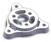
Figure 1The base of the reaction wheel housing.
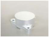
Figure 2 Reaction wheel housing.
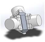
Figure 3 Reaction wheel tetrahedral configuration.
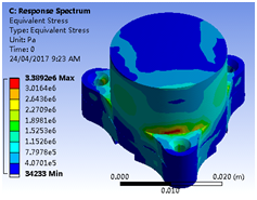
Figure 4 Shock test of reaction wheel housing.
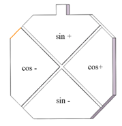
Figure 5 B1-B1 Stator with attached electrodes.
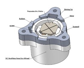
Figure 8 Ultrasonic piezoelectric motor.

Figure 9 Horizontal vibration response.

Figure 10 Vertical vibration response.
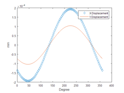
Figure 11 Vertical and horizontal displacements of the driving tip.
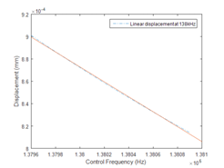
Figure 12 Horizontal vibration response at 138kHz.
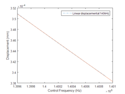
Figure 13 Horizontal vibration response at 140kHz.
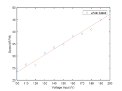
Figure 14 Speed of piezoelectric motor at 139kHz.
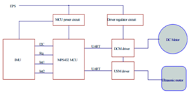
Figure 15 Ultrasonic piezoelectric motor.
Reaction wheel control
The reaction wheel system was integrated to a 3U CubeSat for testing; Figure 15 shows the schematic diagram of the reaction wheel control, both actuators are controlled by the MPS432 microcontroller.
Results
The reaction wheel system was integrated to different nano-satellite platforms for testing and optimization; the reaction wheel system was also tested on an air bearing table with laser positioning and high-speed camera. The results show the single reaction wheel system can generate a 1.764 degree/s change in yaw angle on a 3.5kg 3U CubeSat by the current control algorithm. The attitude control by the ultrasonic piezoelectric motor is still being studied; the speed of the piezoelectric motor will be affected by the change in temperature and pressure in the space environment. More studies need to be accomplished to optimize the performance of the reaction wheel system. The result in Fig. 14 shows that the ultrasonic piezoelectric motor has a linear output at low-speed zone, this supports the design concept of this dual actuator reaction wheel, the piezoelectric motor can increase the linearity of the reaction wheel system for providing a precise attitude control.
Conclusion
This paper describes the concept and design of an innovative dual actuator attitude control system for nano-satellites, the design will be further optimized, especially the attitude control behaviour of the ultrasonic piezoelectric motor will be intensely studied; more influences from the environment will also be considered. This dual actuator reaction wheel will be installed to AMMEQ-1 CubeSat for in orbit technology demonstrations.
Acknowledgement
This research is supported by The School of Aerospace, Mechanical and Mechatronics Engineering at The University of Sydney, and The Centre for Quantum Technologies (CQT) at The National University of Singapore.
Conflicts of Interest
The authors declare that there is no conflict of interest.
References
- Kim E, Wu X, Kwan T, et al. Preliminary System Design for AMMEQ-1: A Step towards QKD for AMMEQ-1, a 3U Cubesat. Japan: 31st International Symposium on Space Technology and Science; 2017.
- Kayal H, Baumann F, Kwan T, et al. BEESAT–A Pico Satellite of TU Berlin for the In-Orbit Verification of Miniaturised Wheels. Scotland: Proceedings of 59th International Astronautical Conference; 2008.
- Astro and Feinwerktechnik Adlershof GmbH. Berlin; 2017.
- Stetson JB. Reaction Wheel Low-speed Compensation Using a Dither Signal. Journal of Guidance, Control, and Dynamics. 1993;16(4):617‒622.
- Toshiiku S, Takashi K. An Introduction to Ultrasonic motors. 1st ed. UK: Clarendon Press; 1993. 141‒151 p.
- Wertz JR. Spacecraft Attitude Determination and Control. London: Kluwer Academic Publishers; 1978. 858 p.
- Rocket and Space Technology, Atmospheric Properties. 2017.
- Rawashdeh SA, Lumpp JE. Aerodynamic Stability for CubeSats at ISS Orbit. JOSS. 2013;2(1):85‒104.
- Springmann JC, Cutler JW, Bahcivan H. Magnetic Sensor Calibration and Residual Dipole Characterization for Application to Nanosatellites. Canada: AIAA/AAS Astrodynamics Specialist Conference; 2010. 14 p.
- Kumar S, Divyanshu S, Hegde SR, et al. Design and Development of 3-axis Reaction Wheel for STUDSAT-2. USA: IEEE Aerospace Conference; 2015.
- Falcon 9 Launch Vehicle Payload User’s Guide. California: Space X; 2015. 69 p.
- Zhao CS. Ultrasonic Motors Technologies and Applications. 1st ed. Beijing: Science Press; 2007. 494 p.
- Chen ZJ, Li XT, Chen JG, et al. A square-plate ultrasonic linear motor operating in two orthogonal first bending mode. IEEE Transactions on ultrasonics, Ferroelectrics and Frequency Control. 2013;60(1):115‒120.
- Yang M, Levesley BH, Walker PG, et al. Amplitude modulation Drive to rectangular plate linear ultrasonic motors with vibrators dimensions 8mmx2.16mmx1mm. IEEE Transactions on Ultrasonics, Ferroelectrics and Frequency Control. 2006;53(12): 2435‒2441.
- Xing YF, Liu B. Exact solutions for the free in-plane vibrations of rectangular plates. Acta Mechanica Solida Sinica. 2009;24(6):556‒567.

©2018 Sun, et al. This is an open access article distributed under the terms of the,
which
permits unrestricted use, distribution, and build upon your work non-commercially.


