eISSN: 2576-4543


Research Article Volume 3 Issue 5
1Division of Mechanical Engineering, Graduate School of Engineering, Mie University, Japan
2Division of Chemistry for Materials, Graduate School of Engineering, Mie University, Japan
3School of Mechanical Engineering, The University of Adelaide, Australia
Correspondence: Akira Nishimura, Division of Mechanical Engineering, Graduate School of Engineering, Mie University, 1577 Kurimamachiya-cho, Tsu, Mie 514-8507, Japan, Tel +81 59 231 9747
Received: September 06, 2019 | Published: September 12, 2019
Citation: Nishimura A, Sakakibara Y, Inoe T, et al. Impact of molar ratio of NH3 and H2O on CO2 reduction performance over Cu/TiO2 photocatalyst. Phys Astron Int J. 2019;3(5):176-182. DOI: 10.15406/paij.2019.03.00179
Cu-doped TiO2 (Cu/TiO2) film photocatalyst was prepared by sol-gel dip-coating, and pulse arc plasma process. The netlike glass fiber was used as a base material for the photocatalyst since it had a porous structure. The CO2 reduction performance with NH3 and H2O into CO and CH4 over the Cu/TiO2 photocatalyst was investigated experimentally under the illumination condition with UV as well as without UV. In addition, the characterization of prepared Cu/TiO2 film coated on netlike glass fiber was analyzed by SEM and EPMA. As a result, the CO2 reduction performance peaks under the condition of CO2/NH3/H2O=1:1:1 in both cases with UV light and without UV light illumination. The highest molar quantity of CO and CH4 per weight of photocatalyst in the reactor is 10.2 μmol/g and 1.76 μmol/g, respectively. Comparing the CO2 reduction characteristics for CO2/NH3/H2O with that for CO2/H2O, it is concluded that the proper combination of NH3 and H2O would be effective for promoting the CO2 reduction performance over Cu/TiO2, for the improving of the reduction performance of Cu/TiO2 being necessary to promote the conversion from NH3 into H2.
Keywords: photocatalyst, Cu/TiO2, CO2 reduction, optimum combination of NH3 and H2O
Due to the increase in the averaged concentration of CO2 in the atmosphere to 408.3 ppmV in April 2019,1 CO2 reduction or utilization technologies to recycle CO2 are urgently required. This study focuses on CO2 reduction and conversion into fuel through photocatalytic process. TiO2 is the principle catalyst used for almost all types of photocatalytic reaction. It is well reported that CO2 can be reduced into fuels e.g. CO, CH4, CH3OH, and H2 etc. with TiO2 as the photocatalyst under ultraviolet (UV) light illumination.2,4–7 However, the CO2 reduction performance with TiO2 is still low since TiO2 has a large bandgap energy (~3.2 eV) and a rapid recombination rate of electron and hole.5 Recently, studies on CO2 photochemical reduction by TiO2 have been carried out to promote the performance by extending absorption range towards visible region.8–15 For example, the previous studies investigated doping previous metal such as Pt8 Ag,9 Au,10 Cu11,12 composite material formed by GaP and TiO2,13 complex assembly CdS/TiO2 to utilize two photocatalysts that have different band gaps,14+ and carbon-based AgBr nanocomposites TiO215 to promote the performance of TiO2. Though the CO2 reduction performance was improved by these attempts, the concentrations of the products were still low, which was ranging from 1mol/g-cat to 150 μmol/g-cat.8–15 Therefore, a breakthrough in increasing the concentration level of products is necessary to advance the CO2 reduction technology in order to make the technology practically useful.
It was reported that doping transition metal was a useful technique for extending the absorbance of TiO2 into the visible region.16 For doping, various metal ions have been used, but among them, Cu is considered as a favorite candidate. Cu can extend the absorption band to 600-800 nm.17,18 which covers the whole visible light range. Cu-decorated TiO2 nanorod thin film performed ten times yields as large as TiO2 for C2H5OH production.19 Cu loaded Ni/TiO2 also showed the good performance which yielded eight times as large as TiO2 for CH4 production.20 Even under UV light illumination condition, Cu-decorated TiO2 nanorod film yielded ten times as large as TiO2 for CH4 production.21 Noble metal such as Pt and Au are too expensive to be used in industrial scale. Therefore, Cu is the best candidate because of its high efficiency and low cost compared to noble metals. Due to its availability as well as above described characteristics, Cu is selected as the dopant in this study. Since a reductant is necessary for CO2 reduction to produce fuel, H2O and H2 are usually used as reductant according to the review papers.5,7 To promote the CO2 reduction performance, it is important to select the optimum reductant which provides the proton (H+) for the reduction reaction. According to the previous studies,22–25 the reaction scheme to reduce CO2 with H2O can be summarized as shown below:
<Photocatalytic reaction>
(1)
<Oxidization>
(2)
<Reduction>
(3)
(4)
The reaction scheme to reduce CO2 with H2 can be summarized as shown below:26
<Photocatalytic reaction>
(5)
<Oxidization>
(6)
<Reduction>
(7)
(8)
(9)
(10)
(11)
Though there are some reports on CO2 reduction with H2O or H2,5,7 the effect of NH3 having 3H+ which is superior to H2O and H2 on CO2 reduction performance of photocatalyst is not investigated yet without the previous study conducted by Nishimura et al.30 using Fe/TiO2.27 Since the previous study27 investigated only one combination ratio of CO2, NH3 and H2O, the effect of ratio of CO2, NH3 and H2O on CO2 reduction performance of metal doped TiO2 is not clarified yet. It is important to investigate the combination ratio of CO2, NH3 and H2O in order to promote the CO2 reduction performance of Cu/TiO2 photocatalyst. The reaction scheme to reduce CO2 with NH3 can be summarized as shown below:26,28
<Photocatalytic reaction>
(12)
<Oxidization>
(13)
(14)
<Reduction>
(15)
(16)
(17)
(18)
(19)
Consequently, the purpose of this study is to clarify the effect of molar ratio of CO2 to NH3 and H2O on the performance of CO2 reduction with Cu/TiO2. The CO2 reduction performance with NH3 and H2O using Cu/TiO2 coated on netlike glass fiber as photocatalyst under the condition of illuminating Xe lamp with or without UV light was investigated. The combination of CO2/NH3/H2O was changed for 1:1:1, 1:0.5:1, 1:1:0.5, 1:0.5:0.5, 3:2:3, 3:8:12 to determine the optimum ratio of CO2/NH3/H2O. According to the reaction scheme to reduce CO2 with H2O or NH3 as shown above, the theoretical moral ratio of CO2/H2O to produce CO or CH4 is 1:1 or 1:4, respectively, while that of CO2/NH3 to produce CO or CH4 is 3:2, 3:8, respectively. Therefore, this study assumes that the moral ratio of CO2/NH3/H2O=3:2:3 and 3:8:12 is theoretical moral ratio to produce CO and CH4, respectively. In addition, the combination of CO2/H2O was also changed for 1:1, 1:0.5, 3:12 to clarify the effect of NH3 on the CO2 reduction characteristics of Cu/TiO2.
Experiments
Preparation of Cu/TiO2 film
Sol-gel and dip-coating process was used for preparing TiO2 film. TiO2 sol solution was made by mixing [(CH3)2CHO]4Ti (purity of 95 wt%, Nacalai Tesque Co.) of 0.3 mol, anhydrous C2H5OH (purity of 99.5 wt%, Nacalai Tesque Co.) of 2.4 mol, distilled water of 0.3 mol, and HCl (purity of 35 wt%, Nacalai Tesque Co.) of 0.07 mol. In this study, TiO2 film is coated by sol-gel and dip-coating process on netlike glass fiber (SILIGLASS U, Nihonmuki Co.). The glass fiber whose diameter is about 10 µm weaved as a net, resulting in the diameter of collected fiber of approximately 1 mm. According to the specifications of netlike glass fiber, the porous diameter of glass fiber is approximately 1 nm and the specific surface area is approximately 400 m2/g. The composition of netlike glass fiber is SiO2 of 96 wt%. The aperture area is approximately 2 mm×2 mm. Due to the porous characteristic of the netlike glass fiber, TiO2 film can be captured on netlike glass fiber easily during sol-gel and dip-coating process. In addition, it can be expected that CO2 would be more easily absorbed by the prepared photocatalyst since the fiber has the porous characteristics. Netlike glass fiber was cut to disc, and its diameter and thickness were 50 mm and 1 mm, respectively. The netlike glass disc was dipped into TiO2 sol solution at the speed of 1.5 mm/s and pulled up at the fixed speed of 0.22 mm/s. Then, it was dried out and fired under the controlled firing temperature (FT) and firing duration time (FD), resulting that TiO2 film was fastened on the base material. FT and FD were set at 623 K and 180 s, respectively.
After the coating of TiO2, Cu is loaded on the TiO2 coated netlike glass fiber by pulse arc plasma gun method which can emit nanosized Cu particles uniformly by applying high electrical potential difference. The pulse number can control the quality of Cu loaded on TiO2. In this study, the pulse number is set at 100. Cu was loaded on TiO2 film by pulse arc plasma gun method. The pulse arc plasma gun device (ULVAC, Inc., ARL-300) having Cu electrode whose diameter was 10 mm was applied for Cu loading. After the netlike glass fiber coated with TiO2 was set in the chamber of the pulse arc plasma gun device, where was vacuumed, the nanosized Cu particles were emitted from Cu electrode with applying the electrical potential difference of 200 V. The pulse arc plasma gun can evaporate Cu particle over the target in the circle area whose diameter is 100 mm when the distance between Cu electrode and the target is 160 mm. Since the distance between Cu electrode and TiO2 film was 150 mm, Cu particle can be evaporated over TiO2 film uniformly. The amount of loaded Cu was controlled by pulse number.
Characterization of Cu/TiO2 film
The structure and crystallization characteristics of Cu/TiO2 film were evaluated by SEM (JXA-8530F, JEOL Ltd.) and EPMA (JXA-8530F, JEOL Ltd.). Since these measuring instruments use electron for analysis, the sample should be an electron conductor. Since netlike glass disc is not an electron conductor, the carbon vapor deposition was conducted by the dedicated device (JEE-420, JEOL Ltd.) for Cu/TiO2 coated on netlike glass disc before analysis. The thickness of carbon deposited on samples was approximately 20-30 nm. The electron probe emits the electrons to the sample under the acceleration voltage of 15 kV and the current of 3.0×10⁻⁸ A, when the surface structure of sample is analyzed by SEM. The characteristic X-ray is detected by EPMA at the same time, resulting that the concentration of chemical element is analyzed according to the relationship between the characteristic X-ray energy and the atomic number. The spatial resolution of SEM and EPMA is 10 µm. The EPMA analysis helps not only to understand the coating state of prepared photocatalyst but also to measure the amount of doped metal within TiO2 film on the base material.
CO2 reduction experiment
Figure 1 shows the experimental set-up of the reactor composing of stainless tube (100 mm (H.)×50 mm (I.D.)), Cu/TiO2 film coated on netlike glass disc (50 mm (D.)×1 mm (t.)) located on the teflon cylinder (50 mm (H.)×50 mm (D.)), a quartz glass disc (84 mm (D.) ×10 mm (t.)), a sharp cut filter cutting off the light whose wavelength is below 400 nm (SCF–49.5C-42L, SIGMA KOKI CO. LTD.), a 150 W Xe lamp (L2175, Hamamatsu Photonics K. K.), mass flow controller and CO2 gas cylinder. The volume of reactor to charge CO2 is 1.25×10⁻⁴ m3. The light of Xe lamp which is located inside the stainless tube illuminates Cu/TiO2 film coated on the netlike glass disc through the sharp cut filter and the quartz glass disc that are at the top of the stainless tube. The wavelength of light from Xe lamp is ranged from 185 nm to 2000 nm. Since the sharp cut filter can remove UV components of the light form the Xe lamp, the wavelength of light from Xe lamp is ranged from 401 nm to 2000 nm with the filter. Figure 2 shows the performance of the sharp cut filter to cut off the wavelength of the light, which can prove to remove the light whose wavelength is below 400 nm. The average light intensity of Xe lamp without and with the sharp cut filter are 58.2 mW/cm2 and 33.8 mW/cm2, respectively.
In the CO2 reduction experiment with H2O or NH3 + H2O, after purging the reactor with CO2 gas of 99.995 vol% purity introduced in the reactor, which was pre-vacuumed by a vacuum pump, for 15 minutes, the valves located at the inlet and the outlet of reactor were closed. After confirming the pressure and gas temperature in the reactor at 0.1 MPa and 298 K, respectively, the distilled water or NH3 aqueous solution (NH3; 50 vol%), which was changed according to the planed molar ratio, was injected into the reactor through gas sampling tap, and Xe lamp illumination was turned on the same time. The distilled water or NH3 aqueous solution injected vaporized completely in the reactor. Due to the heat of Xe lamp, the temperature in the reactor was attained at 343 K within an hour and kept at approximately 343 K during the experiment. The molar ratio of CO2/NH3/H2O was set at 1:1:1, 1:0.5:1, 1:1:0.5, 1:0.5:0.5, 3:2:3, 3:8:12, respectively. The gas in the reactor was sampled every 24 hours during the experiment. The gas samples were analyzed by FID gas chromatograph (GC353B, GL Science) and methanizer (MT221, GD Science). Minimum resolution of FID gas chromatograph and methanizer is 1 ppmV.
Characterization of Cu/TiO2 film
Figure 3 shows SEM image of Cu/TiO2 film coated on netlike glass disc. The SEM image was taken at 1500 times magnification. Figure 4 shows EPMA images of Cu/TiO2 film coated on netlike glass disc. EPMA analysis was carried out for SEM images taken by 1500 times magnification. In EPMA image, the concentrations of each element in observation area are indicated by the different colors. Light colors, for example, white, pink, and red indicate that the amount of element is large, while dark colors like black and blue indicate that the amount of element is small. From these figures, it can be observed that TiO2 film with teeth like shape was coated on netlike glass fiber. During firing process, the temperature profile of TiO2 solution adhered on the netlike glass disc was not even due to the different thermal conductivities of Ti and SiO2. Their thermal conductivities of Ti and SiO2 at 600 K are 19.4 W/(m・K) and 1.82 W/(m・K), respectively.29 Due to the thermal expansion and shrinkage around netlike glass fiber, thermal crack formed on TiO2 film. Therefore, TiO2 film on netlike glass fiber was teeth like. As to Cu, it is observed from Figure 4 that nanosized Cu particles loaded on TiO2 uniformly, resulting from that the pulse arc plasma method can emit nanosized Cu particles. To evaluate the amount of loaded Cu within TiO2 film quantitatively, the observation area, which is the center of netlike glass disc, of diameter of 300 µm is analyzed by EPMA. The ratio of Cu to Ti in this observation area is counted by averaging the data obtained in this area. As a result, the weight percentages of elements Cu and Ti in the Cu/TiO2 film are 2.14 wt% and 97.86 wt%, respectively. This ratio is approximately same as the previous study prepared Cu/TiO2 by pulse arc plasma gun method.30
Effect of molar ratio of CO2 to NH3 and H2O on CO2 reduction performance
Figures 5 and Figures 6 show the concentration changes of formed CO and CH4 along the time under the Xe lamp with UV light, respectively. The amount of Cu/TiO2 on the netlike glass disc is 0.05 g. Before the experiments, a blank test, that was running the same experiment without illumination of Xe lamp, had been carried out to set up a reference case. No fuel was produced in the blank test as expected. According to Figures 5 and 6, the CO2 reduction performance is the highest for the molar ratio of CO2/NH3/H2O=1:1:1. According to the reaction scheme to reduce CO2 with H2O or NH3, the theoretical molar ratio of CO2/H2O to produce CO or CH4 is 1:1 or 1:4, respectively, while that of CO2/NH3 to produce CO or CH4 is 3:2, 3:8, respectively. Therefore, this study assumes that the molar ratio of CO2/NH3/H2O=3:2:3 and 3:8:12 is theoretical molar ratio to produce CO and CH4, respectively. However, the molar ratio of CO2/NH3/H2O=1:1:1 is not matched with these theoretical molar ratios to produce CO and CH4. Since the ionized Cu doped with TiO2 provides free electron for the reduction reaction process,31 the reductants of NH3 and H2O which are less than the values indicated in the theoretical reaction scheme are enough for producing CO and CH4 in this study. The highest molar quantity of CO and CH4 per weight of photocatalyst in the reactor, which is obtained for the molar ratio of CO2/NH3/H2O=1:1:1, is 10.2 µmol/g and 1.76 µmol/g, respectively.
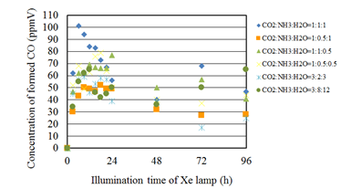
Figure 5 Comparison of concentration of formed CO among several molar ratios of CO2/NH3/H2O under the illumination condition with UV light.

Figure 6 Comparison of concentration of formed CH4 among several molar ratios of CO2/NH3/H2O under the illumination condition with UV light.
In addition, it is confirmed from Figure 5 that the concentration of formed CO is increased from the start of illumination of Xe lamp and decreased after attaining the peak concentration. However, the concentration of formed CO increases again after 48 hours. It is believed that the decrease in the concentration of formed CO is resulted from the oxidization reaction between CO and O2 which is by-product as shown in Eq. (2).32 Since the produced CO might be remained near the photocatalyst due to high absorption performance of netlike glass fiber, this oxidization reaction is thought to be occurred. The increase in the concentration of formed CO after 48 hours might be due to the difference of reaction rates between CO2/H2O and CO2/NH3 condition. It is also revealed that the maximum concentration of formed CO is higher when the molar of NH3 is higher than that of H2O. Since the number of H+ which can be provided is 3 and 2 for NH3 and H2O, respectively, it is considered that NH3 is effective for promoting the reduction performance of Cu/TiO2. Furthermore, it is found from Figure 5 and Figure 6 that the concentration of formed CH4 starts to increase after the decreasing of CO concentration. According to the reaction schemes, the more H+ and electron are needed to produce CH4, resulting that the production of CH4 starts later.
Figure 7 shows the concentration changes of formed CO along the time under the Xe lamp without UV light. In this experiment, CO is the only fuel produced from the reactions, i.e. no CH4 was detected. Before the experiments, a blank test, that was running the same experiment without illumination of Xe lamp, had been carried out to set up a reference case. No CO or CH4 was produced in the blank test as expected. According to Figure 7, the CO2 reduction performance is the best for the molar ratio of CO2/NH3/H2O=1:1:1 in the case of illumination condition without UV light. In addition, it is confirmed from Figure 7 that the concentration of formed CO is increased from the start of illumination of Xe lamp and decreased after reaching the maximum concentration. However, the concentration of formed CO is increased gradually again after a while. It can be considered that the same reaction mechanism under the illumination condition with UV light as mentioned above occurred.
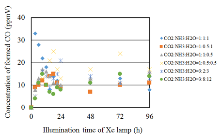
Figure 7 Comparison of concentration of formed CO among several molar ratios of CO2/NH3/H2O under the illumination condition without UV light.
Effect of NH3 on CO2 reduction performance over Cu/TiO2
Figure 8 shows the concentration changes of formed CO along the time under the Xe lamp with UV light for the molar ratio of CO2/H2O=1:1 and that with various CO2/NH3/H2O ratios. Before the experiments, a blank test, that was running the same experiment without illumination of Xe lamp, had been carried out to set up a reference case. No fuel was produced in the blank test as expected. It is seen from Figure 8 that the concentration of formed CO for the molar ratio of CO2/H2O=1:1 shows the peak soon after the start of illumination of Xe lamp and decreases gradually. It is thought that the decrease in the concentration of formed CO is caused by the oxidization reaction with CO and O2.32 In addition, it is found that the concentration of formed CO for every CO2/NH3/H2O condition is larger than that for the molar ratio of CO2/H2O=1:1. Therefore, it can conclude that the combination of NH3 and H2O is effective for the promotion of the CO2 reduction performance over Cu/TiO2.
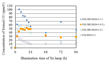
Figure 8 Comparison of concentration of formed CO between the molar ratio of CO2/H2O=1:1 and several molar ratios of CO2/NH3/H2O whose molar ratio of CO2/H2O is 1:1 under the illumination condition with UV light.
Figure 9 shows the concentration changes of formed CO along the time under the Xe lamp with UV light for the molar ratio of CO2/H2O=1:0.5 and that with various CO2/NH3/H2O ratios. It is seen from Figure 9 that the concentration of formed CO for the molar ratio of CO2/H2O=1:0.5 shows the peak soon after the start of illumination of Xe lamp and decreases gradually, which indicates the same tendency as the molar ratio of CO2/H2O=1:1. It is also seen that the concentration of formed CO for every CO2/NH3/H2O condition is larger than that for the molar ratio of CO2/H2O=1:0.5. In addition, the concentration of formed CO keeps some value approximately without rapid decrease before 24 h for CO2/NH3/H2O conditions compared to the molar ratio of CO2/H2O=1:0.5. According to the reaction scheme to reduce CO2 with NH3 as shown before, the more reaction step is needed to produce CO since NH3 should be converted into H2. Therefore, it is believed that the time to produce CO is longer compared to the molar ratio of CO2/H2O=1:0.5.
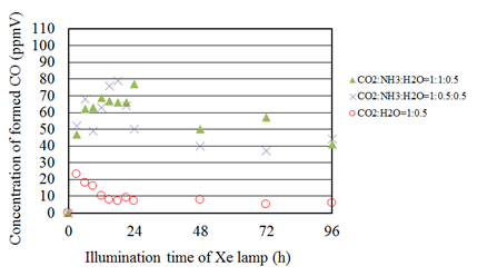
Figure 9 Comparison of concentration of formed CO between the molar ratio of CO2/H2O=1:0.5 and several molar ratios of CO2/NH3/H2O whose molar ratio of CO2/H2O is 1:0.5 under the illumination condition with UV light.
Figure 10 shows the concentration changes of formed CO along the time under the Xe lamp with UV light for the molar ratio of CO2/H2O=3:12 and that with various CO2/NH3/H2O ratios. It is seen from Figure 10 that the concentration of formed CO for the molar ratio of CO2/H2O=3:12 shows the peak soon after the start of illumination of Xe lamp and decreases gradually. In addition, the concentration of formed CO restarts to increase and gradually decrease again. This trend is different from the other CO2/H2O conditions. The ratio of H2O is larger in this experiment compared to others, which indicates larger reductants provided for reduction reaction. Therefore, it is believed to keep CO production even though the oxidization reaction with CO and O2 starts. Furthermore, it is also seen that the concentration of formed CO for the CO2/NH3/H2O condition is larger than that for the molar ratio of CO2/H2O=3:12. Consequently, it is revealed that the combination of NH3 and H2O is effective for promotion of the CO2 reduction performance of Cu/TiO2 for all conditions investigated in this study.
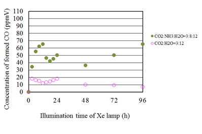
Figure 10 Comparison of concentration of formed CO between the molar ratio of CO2/H2O=3:12 and several molar ratios of CO2/NH3/H2O whose molar ratio of CO2/H2O is 3:12 under the illumination condition with UV light.
In this study, the highest molar quantity of CO and CH4 per weight of photocatalyst in the reactor, which is obtained for the molar ratio of CO2/NH3/H2O=1:1:1, is 10.2 μmol/g and 1.76 µmol/g, respectively. Compared to the previous research on CO2 reduction with H2 and H2O over pure TiO2, the CO production performance of photocatalysts prepared in this study is approximately 35 times as large as that reported in references,26,33 which is owing to not only Cu doping but also the combination of NH3 and H2O. The CO production performance over the Cu/TiO2 prepared in this study is approximately 3 times as large as that reported in the reference.12 However, the CH4 production performance of Cu/TiO2 prepared in this study is one twentieth as large as that of Cu/TiO2 reported in the other reference.34 Therefore, it is necessary to promote the conversion from NH3 into H2 in order to improve the reduction performance according to the reaction scheme to reduce CO2 with NH3. One way to promote the conversion from NH3 into H2 is thought to be using Pt as a dopant. It was reported that Pt/TiO2 was effective to dissolve NH3 aqueous solution into N2 and H2.28 Another way to further promote the CO2 reduction performance may be double overlapping arrangement of Cu/TiO2 coated on netlike glass disc since the electron transfer between two overlapped photocatalyst was promoted by overlapping.35 It can be suggested that different metals such as Cu and Pt should be doped on the higher and the lower positioned photocatalysts discs since the co-doped such as PbS-Cu/TiO2, Cu-Fe/TiO2, Cu-Ce/TiO2, Cu-Mn/TiO2 and Cu-CdS/TiO2 promoted the CO2 reduction performance of TiO2 under the CO2/H2O condition.5,7
Based on the investigation in this experimental study, the following conclusions can be drawn.
JSPS KAKENHI.
The authors would like to gratefully thank from JSPS KAKENHI Grant Number 16K06970 for the financial support of this work.
The authors declare that there is no conflict of interest regarding the publication of this paper.

©2019 Nishimura, et al. This is an open access article distributed under the terms of the, which permits unrestricted use, distribution, and build upon your work non-commercially.