Submit manuscript...
eISSN: 2576-4543

Physics & Astronomy International Journal

Review Article Volume 2 Issue 3

A review on the designed low–loss single–mode optical fiber used in fiber–to–the–home networks

Faramarz E Seraji,1 Anahita Khodakarami,2 Mansour Rezaie Mersagh2

1Optical Communication Group, Iran Telecom Research Center, Iran
2Physics Group, Islamic Azad University North Tehran Branch, Tehran

Correspondence: Faramarz E Seraji, Faculty member Optical Communication Group, Department of Communication Technology, Iran Telecom Research Center, Tehran, Iran, Tel 98?21?84977723

Received: May 20, 2018 | Published: June 22, 2018

Citation: Seraji FE, Khodakarami A, Mersagh MR. A review on the designed low-loss single-mode optical fiber used in fiber-to-the-home networks. Phys Astron Int J. 2018;2(3):250-254. DOI: 10.15406/paij.2018.02.00094

Download PDF

Abstract

Fiber-to-the-home (FTTH) technology provides the ability to transmit telecommunication data at a maximum level. In order to achieve this technology, fibers with the lowest bending and splice losses are required. In this paper, the losses of bending and splice joints in single mode optical fibers have been reviewed with a variety of designs, including holey fibers, nanoscale optical fibers, and microstructured optical fibers. By comparing the losses of these fibers, we chose the best fiber with the lowest losses in designing FTTH that is used for two purposes of reducing costs and improving optical network performances. These fibers have advantages such as low bending radius, wavelength and mode field diameter, which can be effective in minimizing bending losses.

Keywords: holey optical fibers, microstructured optical fibers, nanoscale optical fibers, bending losses, bending radius, splice losses, FTTH

Introduction

For fiber-to-the-home (FTTH) networks, optical fibers should be insensitive to bending in order to minimize installation costs and improve the network performance.1 For installation of optical fibers at home, the used fibers must have a minimum bending loss less than 0.1dB/km.2

In order to reduce the bending losses in optical fibers used in FTTH networks, the design of holey optical fibers (HOF) has been proposed that are referred to as microstructure optical fibers (MOF). In this design, with a bending radius of 5mm, the mode field diameter (MFD) was 9.3μm MathType@MTEF@5@5@+= feaagKart1ev2aqatCvAUfeBSjuyZL2yd9gzLbvyNv2CaerbuLwBLn hiov2DGi1BTfMBaeXatLxBI9gBaerbd9wDYLwzYbItLDharqqtubsr 4rNCHbGeaGqiVGc9Vfea0lb91rFfpec8Eeeu0xXdbba9frFj0=OqFf ea0dXdd9vqaq=JfrVkFHe9pgea0dXdar=Jb9hs0dXdbPYxe9vr0=vr 0=vqpWqaaeaabiGaaiaacaqaaeaadaqaaqaaaOqaaKqzGeGaaGyoai aac6cacaaIZaGaeqiVd0MaaOyBaaaa@3C95@ at a wavelength of 1550nm and cutoff wavelength of 1100nm. The measured bending loss and splice loss were obtained less than 0.011dB/turn and 0.08dB, respectively.3-5

One of the fibers for this technology is a fiber of nanoscale structure, insensitive to bending, with ultra-low bending loss is designed and manufactured. Bending radius of 5mm at an operating wavelength of 1550nm, yielded a bending loss of less than 0.1dB/trun.6 Other optical parameters of the designed fiber fully comply with the standard communications grade single-mode fibers (SMF).

As the FTTH networks deployment is increasing, optical fiber cables are required to be handled easily with less construction space. Under this circumstance, an SMF providing small bending radius is strongly needed.5

A novel single-mode HOF bending-insensitive with doped core and two layers of air-holes with different diameters is proposed. The fiber has an MFD of 9.3μm MathType@MTEF@5@5@+= feaagKart1ev2aqatCvAUfeBSjuyZL2yd9gzLbvyNv2CaerbuLwBLn hiov2DGi1BTfMBaeXatLxBI9gBaerbd9wDYLwzYbItLDharqqtubsr 4rNCHbGeaGqiVGc9Vfea0lb91rFfpec8Eeeu0xXdbba9frFj0=OqFf ea0dXdd9vqaq=JfrVkFHe9pgea0dXdar=Jb9hs0dXdbPYxe9vr0=vr 0=vqpWqaaeaabiGaaiaacaqaaeaadaqaaqaaaOqaaKqzGeGaaGyoai aac6cacaaIZaGaeqiVd0MaaOyBaaaa@3C95@ at operating wavelength of 1550nm and a cutoff wavelength below 1100nm, showed a bending loss of 0.011dB/turn at 1550nm for a bending radius of 5mm and a low splice loss of 0.08dB per fusion when spliced to a conventional SMF.5

Another novel MOF for use in FTTH, with 12 air-holes in its cladding is reported.7 The bending losses of this novel MOF at 2mm and 5mm bending-radius is reported less than 0.1dB and 0.049dB, respectively, at 1550nm wavelength. The splice loss between the novels MOF with standard SMF is measured as 0.12dB. This presented novel MOF technology is a strong candidate to achieve low-loss bending-insensitive solutions in comparison to conventional communication optical fibers.

In this paper, these reported optical fibers, designed for use in FTTH networks have been studied and compared. According to reported measurements, the minimum bending losses for each optical fiber, depending on different parameters such as bending radius, MFD, and operating wavelength, are determined and then the best designed fiber suitable for use in FTTH technology will be introduced.

Investigating the design of optical fibers insensitive to bending

Increasing demands for high capacity and low cost of optical communication systems have increased the importance of high-volume optical fibers with flexible structures. This is achieved when optical fibers can be used with a minimum bending radius.

Meanwhile, conventional single-mode optical fibers have a shortcoming of having a minimum bending radius of 5mm which is required for acceptable fiber functionality in FTTH networks. Therefore, there should be a lot of space required in using these types of fibers. Thus, for the FTTH networks, optical fibers that are not sensitive to bending are preferred for better network performances.5,7-12

Holey Optical fiber structure

For applications in the FTTH networks, optical fibers should have low bending losses, shorter cutoff wavelengths at higher modes, and MFD that are consistent with conventional optical fibers. In recent years, photonic crystal fibers (PCFs), also known as holey optical fibers (HOF) or microstructured optical fiber (MOF), have attracted the attention of researchers for their unique features that are not found in conventional optical fibers.

The HOF has at least one layer of air-holes in the cladding region that surrounds the central area named as core. In Figure 1, two types of HOFs are shown, with one layer (Figure 1A) and two layers (Figure 1B) of air-holes arranged in a triangular lattice form in the cladding, where a MathType@MTEF@5@5@+= feaagKart1ev2aqatCvAUfeBSjuyZL2yd9gzLbvyNv2CaerbuLwBLn hiov2DGi1BTfMBaeXatLxBI9gBaerbd9wDYLwzYbItLDharqqtubsr 4rNCHbGeaGqipDI8FfYJH8YrFfeuY=Hhbbf9v8qqaqFr0xc9pk0xbb a9q8WqFfea0=yr0RYxir=Jbba9q8aq0=yq=He9q8qqQ8frFve9Fve9 Ff0dmeaabaqaciGacaGaaeqabaWaaeaaeaaakeaajugibiaadggaaa a@3719@ denotes the core radius, d 1 MathType@MTEF@5@5@+= feaagKart1ev2aqatCvAUfeBSjuyZL2yd9gzLbvyNv2CaerbuLwBLn hiov2DGi1BTfMBaeXatLxBI9gBaerbd9wDYLwzYbItLDharqqtubsr 4rNCHbGeaGqipDI8FfYJH8YrFfeuY=Hhbbf9v8qqaqFr0xc9pk0xbb a9q8WqFfea0=yr0RYxir=Jbba9q8aq0=yq=He9q8qqQ8frFve9Fve9 Ff0dmeaabaqaciGacaGaaeqabaWaaeaaeaaakeaajugibiaadsgalm aaBaaajeaibaqcLbmacaaIXaaajeaibeaaaaa@3985@ and d 2 MathType@MTEF@5@5@+= feaagKart1ev2aaatCvAUfeBSjuyZL2yd9gzLbvyNv2CaerbuLwBLn hiov2DGi1BTfMBaeXatLxBI9gBaerbd9wDYLwzYbItLDharqqtubsr 4rNCHbGeaGqipDI8FfYJH8YrFfeuY=Hhbbf9v8qqaqFr0xc9pk0xbb a9q8WqFfea0=yr0RYxir=Jbba9q8aq0=yq=He9q8qqQ8frFve9Fve9 Ff0dmeaabaqaciGacaGaaeqabaWaaeaaeaaakeaajugibiaadsgalm aaBaaajeaibaqcLbmacaaIYaaajeaibeaaaaa@3985@ are diameters air-holes of the inner and the outer layers, respectively, and Λ MathType@MTEF@5@5@+= feaagKart1ev2aqatCvAUfeBSjuyZL2yd9gzLbvyNv2CaerbuLwBLn hiov2DGi1BTfMBaeXatLxBI9gBaerbd9wDYLwzYbItLDharqqtubsr 4rNCHbGeaGqiVCI8FfYJH8YrFfeuY=Hhbbf9v8qqaqFr0xc9pk0xbb a9q8WqFfea0=yr0RYxir=Jbba9q8aq0=yq=He9q8qqQ8frFve9Fve9 Ff0dmeaabaqaciGacaGaaeqabaWaaeaaeaaakeaajugibiabfU5amb aa@3788@ represents the pitch of the holes in the cladding region.5 It is noted that d 1 MathType@MTEF@5@5@+= feaagKart1ev2aqatCvAUfeBSjuyZL2yd9gzLbvyNv2CaerbuLwBLn hiov2DGi1BTfMBaeXatLxBI9gBaerbd9wDYLwzYbItLDharqqtubsr 4rNCHbGeaGqipDI8FfYJH8YrFfeuY=Hhbbf9v8qqaqFr0xc9pk0xbb a9q8WqFfea0=yr0RYxir=Jbba9q8aq0=yq=He9q8qqQ8frFve9Fve9 Ff0dmeaabaqaciGacaGaaeqabaWaaeaaeaaakeaajugibiaadsgalm aaBaaajeaibaqcLbmacaaIXaaajeaibeaaaaa@3985@ and d 2 MathType@MTEF@5@5@+= feaagKart1ev2aqatCvAUfeBSjuyZL2yd9gzLbvyNv2CaerbuLwBLn hiov2DGi1BTfMBaeXatLxBI9gBaerbd9wDYLwzYbItLDharqqtubsr 4rNCHbGeaGqipDI8FfYJH8YrFfeuY=Hhbbf9v8qqaqFr0xc9pk0xbb a9q8WqFfea0=yr0RYxir=Jbba9q8aq0=yq=He9q8qqQ8frFve9Fve9 Ff0dmeaabaqaciGacaGaaeqabaWaaeaaeaaakeaajugibiaadsgalm aaBaaajeaibaqcLbmacaaIYaaajeaibeaaaaa@3986@ are not necessarily equal, but are uniform in fiber cross section. The concentration of Germanium in the core region is 37% by weight.
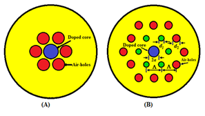
Figure 1 (A) A holey optical fiber with one layer of air–holes, (B) with two layers of air–holes.5

In this design, the cutoff wavelength is a definite number and is equal to 1650nm in order to determine the allowable bending radius for the minimum bending losses, since for the HOFs, the bending losses are higher at longer wavelengths. If the total bending loss for 10 turns is less than 0.5dB at 1650nm, then the radius of each turn will be defined as the allowable bending radius.

Splicing SMF to HOF

In this section, the feasibility of splicing conventional SMF to the HOF with minimum losses will be investigated. The HOF is chosen for splicing because when the air-holes of the HOF are collapsed, its MFD coincides with that of SMF, thus will cause fewer splice losses during the installation process.

The bending losses are the function of the MFD, which on decrease will reduce the bending losses. In Figure 1B, with increasing the value of d 1 MathType@MTEF@5@5@+= feaagKart1ev2aqatCvAUfeBSjuyZL2yd9gzLbvyNv2CaerbuLwBLn hiov2DGi1BTfMBaeXatLxBI9gBaerbd9wDYLwzYbItLDharqqtubsr 4rNCHbGeaGqiVCI8FfYJH8YrFfeuY=Hhbbf9v8qqaqFr0xc9pk0xbb a9q8WqFfea0=yr0RYxir=Jbba9q8aq0=yq=He9q8qqQ8frFve9Fve9 Ff0dmeaabiqaciaacaGaaeaabaWaaeaaeaaakeaajugibiaadsgalm aaBaaajeaibaqcLbmacaaIXaaajeaibeaaaaa@3964@ , the cutoff wavelength would increase, as well. By keeping d 1 MathType@MTEF@5@5@+= feaagKart1ev2aqatCvAUfeBSjuyZL2yd9gzLbvyNv2CaerbuLwBLn hiov2DGi1BTfMBaeXatLxBI9gBaerbd9wDYLwzYbItLDharqqtubsr 4rNCHbGeaGqiVCI8FfYJH8YrFfeuY=Hhbbf9v8qqaqFr0xc9pk0xbb a9q8WqFfea0=yr0RYxir=Jbba9q8aq0=yq=He9q8qqQ8frFve9Fve9 Ff0dmeaabiqaciaacaGaaeaabaWaaeaaeaaakeaajugibiaadsgalm aaBaaajeaibaqcLbmacaaIXaaajeaibeaaaaa@3964@ and Λ MathType@MTEF@5@5@+= feaagKart1ev2aqatCvAUfeBSjuyZL2yd9gzLbvyNv2CaerbuLwBLn hiov2DGi1BTfMBaeXatLxBI9gBaerbd9wDYLwzYbItLDharqqtubsr 4rNCHbGeaGqiVCI8FfYJH8YrFfeuY=Hhbbf9v8qqaqFr0xc9pk0xbb a9q8WqFfea0=yr0RYxir=Jbba9q8aq0=yq=He9q8qqQ8frFve9Fve9 Ff0dmeaabiqaciaacaGaaeaabaWaaeaaeaaakeaajugibiabfU5amb aa@3787@ constant and only changing the value of d 2 MathType@MTEF@5@5@+= feaagKart1ev2aqatCvAUfeBSjuyZL2yd9gzLbvyNv2CaerbuLwBLn hiov2DGi1BTfMBaeXatLxBI9gBaerbd9wDYLwzYbItLDharqqtubsr 4rNCHbGeaGqiVCI8FfYJH8YrFfeuY=Hhbbf9v8qqaqFr0xc9pk0xbb a9q8WqFfea0=yr0RYxir=Jbba9q8aq0=yq=He9q8qqQ8frFve9Fve9 Ff0dmeaabiqaciaacaGaaeaabaWaaeaaeaaakeaajugibiaadsgalm aaBaaajeaibaqcLbmacaaIYaaajeaibeaaaaa@3965@ , one can control the cutoff wavelength and bending losses without altering the values of the MFD.5

When the HOF fiber is spliced to the SMF fiber, the splice point would experience some losses at the joint. To determine the minimum required MFD of the HOF, in order to have total splice losses L s MathType@MTEF@5@5@+= feaagKart1ev2aaatCvAUfeBSjuyZL2yd9gzLbvyNv2CaerbuLwBLn hiov2DGi1BTfMBaeXatLxBI9gBaerbd9wDYLwzYbItLDharqqtubsr 4rNCHbGeaGqiVu0Je9sqqrpepC0xbbL8F4rqqrFfpeea0xe9Lq=Jc9 vqaqpepm0xbba9pwe9Q8fs0=yqaqpepae9pg0FirpepeKkFr0xfr=x fr=xb9adbaqaaeGaciGaaiaabeqaamaabaabaaGcbaqcLbsacaWGmb WcdaWgaaqcbasaaKqzadGaam4Caaqcbasabaaaaa@39FC@ less than 0.3dB at 1550nm operating wavelength, we use the following well-known expression as:5,13

L s =20 log 10 2 w SMF w HOF w SMF 2 + w HOF 2 MathType@MTEF@5@5@+= feaagKart1ev2aaatCvAUfeBSjuyZL2yd9gzLbvyNv2CaerbuLwBLn hiov2DGi1BTfMBaeXatLxBI9gBaerbd9wDYLwzYbItLDharqqtubsr 4rNCHbGeaGqiVu0Je9sqqrpepC0xbbL8F4rqqrFfpeea0xe9Lq=Jc9 vqaqpepm0xbba9pwe9Q8fs0=yqaqpepae9pg0FirpepeKkFr0xfr=x fr=xb9adbaqaaeGaciGaaiaabeqaamaabaabaaGcbiqbeajaaqyfaG GfaaOfaWRfjugibiaadYealmaaBaaajeaibaqcLbmacaWGZbaajeai beaajugibiabg2da9iabgkHiTiaaikdacaaIWaGaciiBaiaac+gaca GGNbWcdaWgaaqcbasaaKqzadGaaGymaiaaicdaaKqaGeqaaKqbaoaa laaakeaajugibiaaikdacaWG3bWcdaWgaaqcbasaaKqzadGaam4uai aad2eacaWGgbaajeaibeaajugibiaadEhalmaaBaaajeaibaqcLbma caWGibGaam4taiaadAeaaKqaGeqaaaGcbaqcLbsacaWG3bWcdaqhaa qcbasaaKqzadGaam4uaiaad2eacaWGgbaajeaibaqcLbmacaaIYaaa aKqzGeGaey4kaSIaam4DaSWaa0baaKqaGeaajugWaiaadIeacaWGpb GaamOraaqcbasaaKqzadGaaGOmaaaaaaqcLbsacaaMc8oaaa@6587@ (1)

where w SMF MathType@MTEF@5@5@+= feaagKart1ev2aaatCvAUfeBSjuyZL2yd9gzLbvyNv2CaerbuLwBLn hiov2DGi1BTfMBaeXatLxBI9gBaerbd9wDYLwzYbItLDharqqtubsr 4rNCHbGeaGqiVu0Je9sqqrpepC0xbbL8F4rqqrFfpeea0xe9Lq=Jc9 vqaqpepm0xbba9pwe9Q8fs0=yqaqpepae9pg0FirpepeKkFr0xfr=x fr=xb9adbaqaaeGaciGaaiaabeqaamaabaabaaGcbaqcLbsacaWG3b WcdaWgaaqcbasaaKqzadGaam4uaiaad2eacaWGgbaajeaibeaaaaa@3BA4@ and w HOF MathType@MTEF@5@5@+= feaagKart1ev2aaatCvAUfeBSjuyZL2yd9gzLbvyNv2CaerbuLwBLn hiov2DGi1BTfMBaeXatLxBI9gBaerbd9wDYLwzYbItLDharqqtubsr 4rNCHbGeaGqiVu0Je9sqqrpepC0xbbL8F4rqqrFfpeea0xe9Lq=Jc9 vqaqpepm0xbba9pwe9Q8fs0=yqaqpepae9pg0FirpepeKkFr0xfr=x fr=xb9adbaqaaeGaciGaaiaabeqaamaabaabaaGcbaqcLbsacaWG3b WcdaWgaaqcbasaaKqzadGaamisaiaad+eacaWGgbaajeaibeaaaaa@3B9B@ are MFDs of the SMF and the HOF, respectively. By inserting the constant value of w SMF MathType@MTEF@5@5@+= feaagKart1ev2aaatCvAUfeBSjuyZL2yd9gzLbvyNv2CaerbuLwBLn hiov2DGi1BTfMBaeXatLxBI9gBaerbd9wDYLwzYbItLDharqqtubsr 4rNCHbGeaGqiVu0Je9sqqrpepC0xbbL8F4rqqrFfpeea0xe9Lq=Jc9 vqaqpepm0xbba9pwe9Q8fs0=yqaqpepae9pg0FirpepeKkFr0xfr=x fr=xb9adbaqaaeGaciGaaiaabeqaamaabaabaaGcbaqcLbsacaWG3b WcdaWgaaqcKfaG=haajugWaiaadofacaWGnbGaamOraaqcbasabaaa aa@3D67@ and the varying values of HOF from 5μm MathType@MTEF@5@5@+= feaagKart1ev2aaatCvAUfeBSjuyZL2yd9gzLbvyNv2CaerbuLwBLn hiov2DGi1BTfMBaeXatLxBI9gBaerbd9wDYLwzYbItLDharqqtubsr 4rNCHbGeaGqiVu0Je9sqqrpepC0xbbL8F4rqqrFfpeea0xe9Lq=Jc9 vqaqpepm0xbba9pwe9Q8fs0=yqaqpepae9pg0FirpepeKkFr0xfr=x fr=xb9adbaqaaeGaciGaaiaabeqaamaabaabaaGcbaqcLbsacaGI1a GaaOiVdiaak2gaaaa@398A@ to 8μm MathType@MTEF@5@5@+= feaagKart1ev2aaatCvAUfeBSjuyZL2yd9gzLbvyNv2CaerbuLwBLn hiov2DGi1BTfMBaeXatLxBI9gBaerbd9wDYLwzYbItLDharqqtubsr 4rNCHbGeaGqiVu0Je9sqqrpepC0xbbL8F4rqqrFfpeea0xe9Lq=Jc9 vqaqpepm0xbba9pwe9Q8fs0=yqaqpepae9pg0FirpepeKkFr0xfr=x fr=xb9adbaqaaeGaciGaaiaabeqaamaabaabaaGcbaqcLbsacaGI4a GaaOiVdiaak2gaaaa@398D@ in the Equation (1), we obtain the splice losses in a given range of MFD of HOF.5 In Figure 2A, the HOF splice losses are calculated in terms of the MFD and plotted for w SMF =2.5μm MathType@MTEF@5@5@+= feaagKart1ev2aaatCvAUfeBSjuyZL2yd9gzLbvyNv2CaerbuLwBLn hiov2DGi1BTfMBaeXatLxBI9gBaerbd9wDYLwzYbItLDharqqtubsr 4rNCHbGeaGqiVu0Je9sqqrpepC0xbbL8F4rqqrFfpeea0xe9Lq=Jc9 vqaqpepm0xbba9pwe9Q8fs0=yqaqpepae9pg0FirpepeKkFr0xfr=x fr=xb9adbaqaaeGaciGaaiaabeqaamaabaabaaGcbaqcLbsacaWG3b WcdaWgaaqcbasaaKqzadGaam4uaiaad2eacaWGgbaajeaibeaajugi biabg2da9iaaikdacaGGUaGaaGynaiaaykW7caaMc8UaaOiVdiaak2 gaaaa@44C0@ .

We note that for values of MF D HOF >MF D SMF MathType@MTEF@5@5@+= feaagKart1ev2aaatCvAUfeBSjuyZL2yd9gzLbvyNv2CaerbuLwBLn hiov2DGi1BTfMBaeXatLxBI9gBaerbd9wDYLwzYbItLDharqqtubsr 4rNCHbGeaGqipu0Je9sqqrpepC0xbbL8F4rqqrFfpeea0xe9Lq=Jc9 vqaqpepm0xbba9pwe9Q8fs0=yqaqpepae9pg0FirpepeKkFr0xfr=x fr=xb9adbaqaaeGaciGaaiaabeqaamaabaabaaGcbaqcLbsacaWGnb GaamOraiaadsealmaaBaaajeaibaqcLbmacaWGibGaam4taiaadAea aKqaGeqaaKqzGeGaeyOpa4JaamytaiaadAeacaWGebWcdaWgaaqcba saaKqzadGaam4uaiaad2eacaWGgbaajeaibeaaaaa@4505@ , the splice loss between them increases exponentially, as depicted in Figure 2A, while for MF D HOF >MF D SMF MathType@MTEF@5@5@+= feaagKart1ev2aaatCvAUfeBSjuyZL2yd9gzLbvyNv2CaerbuLwBLn hiov2DGi1BTfMBaeXatLxBI9gBaerbd9wDYLwzYbItLDharqqtubsr 4rNCHbGeaGqipu0Je9sqqrpepC0xbbL8F4rqqrFfpeea0xe9Lq=Jc9 vqaqpepm0xbba9pwe9Q8fs0=yqaqpepae9pg0FirpepeKkFr0xfr=x fr=xb9adbaqaaeGaciGaaiaabeqaamaabaabaaGcbaqcLbsacaWGnb GaamOraiaadsealmaaBaaajeaibaqcLbmacaWGibGaam4taiaadAea aKqaGeqaaKqzGeGaeyOpa4JaamytaiaadAeacaWGebWcdaWgaaqcba saaKqzadGaam4uaiaad2eacaWGgbaajeaibeaaaaa@4505@ , the trend of splice loss variations will attain a decreasing nature, as shown in Figure 2B.

Figure 2 The splice loss as a function of MFD of the HOF for (A) MF D SMF =5.2 μm MathType@MTEF@5@5@+= feaagKart1ev2aaatCvAUfeBSjuyZL2yd9gzLbvyNv2CaerbdfwBIj xAHbqedmvETj2BSbqefm0B1jxALjhiov2DaerbuLwBLnhiov2DGi1B TfMBaebbnrfifHhDYfgasaacH8srps0lbbf9q8WrFfeuY=Hhbbf9v8 qqaqFr0xc9pk0xbba9q8WqFfea0=yr0RYxir=Jbba9q8aq0=yq=He9 q8qqQ8frFve9Fve9Ff0dmeaabaqaciGacaGaaeqabaWaaqaafaaake aajugibabaaaaaaaaapeGaamytaiaadAeacaWGebWcpaWaaSbaaKqa GeaajugWa8qacaWGtbGaamytaiaadAeaaKqaG8aabeaajugib8qacq GH9aqpcaaI1aGaaiOlaiaaikdacaGGGcWdaiaakY7acaGITbaaaa@476E@ and (B) MF D SMF =11.4μm MathType@MTEF@5@5@+= feaagKart1ev2aqatCvAUfeBSjuyZL2yd9gzLbvyNv2CaerbuLwBLn hiov2DGi1BTfMBaeXatLxBI9gBaerbd9wDYLwzYbItLDharqqtubsr 4rNCHbGeaGqiVCI8FfYJH8YrFfeuY=Hhbbf9v8qqaqFr0xc9pk0xbb a9q8WqFfea0=yr0RYxir=Jbba9q8aq0=yq=He9q8qqQ8frFve9Fve9 Ff0dmeaabaqaciGacaGaaeqabaWaaeaaeaaakeaajugibabaaaaaaa aapeGaamytaiaadAeacaWGebqcfa4damaaBaaajeaibaqcLbmapeGa am4uaiaad2eacaWGgbaal8aabeaajugib8qacqGH9aqpcaaIXaGaaG ymaiaac6cacaaI0aWdaiaakY7acaGITbaaaa@442C@ .5

The result of calculating the splice loss in terms of the MFD for SMF (or HOF) indicates that the MFD has a direct relation with the losses of the splice point between two jointed optical fibers. Therefore, for splicing SMF with HOF, by considering a suitable range for MFD, it is possible to minimize the splice loss between these two types of fibers during installation work.

As it is stated, in terms of losses, HOFs can meet the needs of FTTH networks. The HOF fibers are suitable options for splicing to the SMF. The designs of Germanium-doped core HOFs with typically two layers of air-holes of different diameters in the cladding region are reported. It is shown via numerical and experimental results that it is possible to design an HOF with following parameters: an MFD of 9.3µm at wavelength of 1550nm, a small bending loss of 0.011dB/turn at bending radius of 5mm, and a cutoff wavelength below 11nm by choosing a suitable core radius, hole pitch, and air-hole diameters, as shown in Figure 3.5 The characteristic parameters of the fabricated HOF at 1550nm are presented in Table 1.

Figure 3 The characteristic of bending loss as function of bending radius of HOF and SMF fibers at 1550 nm wavelength.5

Loss (dB/km)

MFD (μm) MathType@MTEF@5@5@+= feaagKart1ev2aaatCvAUfeBSjuyZL2yd9gzLbvyNv2CaerbuLwBLn hiov2DGi1BTfMBaeXatLxBI9gBaerbd9wDYLwzYbItLDharqqtubsr 4rNCHbGeaGqiFGc9Vfea0lb91rFfpec8Eeeu0xXdbba9frFj0=OqFf ea0dXdd9vqaq=JfrVkFHe9pgea0dXdar=Jb9hs0dXdbPYxe9vr0=vr 0=vqpWqaaeaabiGaaiaacaqaaeaadaqaaqaaaOqaaKqzGeGaaiikai abeY7aTjaak2gacaGIPaaaaa@3BB3@

Cutoff λ MathType@MTEF@5@5@+= feaagKart1ev2aqatCvAUfeBSjuyZL2yd9gzLbvyNv2CaerbuLwBLn hiov2DGi1BTfMBaeXatLxBI9gBaerbd9wDYLwzYbItLDharqqtubsr 4rNCHbGeaGqiVGc9Vfea0lb91rFfpec8Eeeu0xXdbba9frFj0=OqFf ea0dXdd9vqaq=JfrVkFHe9pgea0dXdar=Jb9hs0dXdbPYxe9vr0=vr 0=vqpWqaaeaabiGaaiaacaqaaeaadaqaaqaaaOqaaKqzGeGaeq4UdW gaaa@3968@  
(nm)

Dispersion
(ps/nm.km)

Bending loss
(dB/turn)

Bend dia. (10 mm)

Bend dia. (20 mm)

2.3

9.3

1100

21.8

0.011

0.002

Table 1 Characteristic parameters of the fabricated HOF at 1550μm MathType@MTEF@5@5@+= feaagKart1ev2aqatCvAUfeBSjuyZL2yd9gzLbvyNv2CaerbuLwBLn hiov2DGi1BTfMBaeXatLxBI9gBaerbd9wDYLwzYbItLDharqqtubsr 4rNCHbGeaGqiFGc9Vfea0lb91rFfpec8Eeeu0xXdbba9frFj0=OqFf ea0dXdd9vqaq=JfrVkFHe9pgea0dXdar=Jb9hs0dXdbPYxe9vr0=vr 0=vqpWqaaeaabiGaaiaacaqaaeaadaqaaqaaaOqaaKqzGeGaaGymai aaiwdacaaI1aGaaGimaiabeY7aTjaak2gaaaa@3D46@

Worth to note that the HOF bending losses are much less than that of the SMF fiber.5,13 The average measured splice loss at 1550nm is 0.08dB per fusion-splice between two spliced fibers.14

Nanoscale optical fiber structure

Nanoscale optical fiber (NOF) is a new structure of the HOF, which consists of a Germanium-doped core and a nanoscale ring layer in the cladding. This ring consists of condensed nanometer air-holes arranged along the fiber with a diameter of a few hundred nanometers, as shown in Figure 4. This ultra-low bending loss SMF with nanometer-sized ring is designed and manufactured.6,15-17
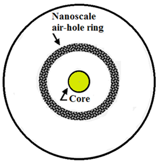
Figure 4 Nanoscale optical fiber insensitive to bending.6

Bending losses of the NOF were measured using 5 turns on different bending radii. Figure 5 compares typical bending losses in terms of bending radius for the NOFs, standard SMF and trench fiber designs at operating wavelength of 1550nm. The results reveal that the bending losses of the NOF are about 500 times better than the standard SMF, and 6–10 times better than the trench fibers. The average bending loss at 5mm radius is 0.03dB/turn.
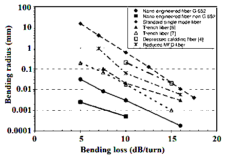
Figure 5 Comparison of bending performance of NOF with standard SMF and trench fibers.6

Other optical parameters of the designed NOF are fully compatible with the standard communications grade. The obtained results are consistent with the OVD fabrication process. The optical characteristics of this type of fiber at wavelengths of 1310 and 1550nm are shown in Table 2. Minimization of bending and splice losses are one of the advantages of the NOF; this is the feature which is important for FTTH networks.7

g
(nm)

MFD
(μm) MathType@MTEF@5@5@+= feaagKart1ev2aaatCvAUfeBSjuyZL2yd9gzLbvyNv2CaerbuLwBLn hiov2DGi1BTfMBaeXatLxBI9gBaerbd9wDYLwzYbItLDharqqtubsr 4rNCHbGeaGqipu0Je9sqqrpepC0xbbL8F4rqqrFfpeea0xe9Lq=Jc9 vqaqpepm0xbba9pwe9Q8fs0=yqaqpepae9pg0FirpepeKkFr0xfr=x fr=xb9adbaqaaeGaciGaaiaabeqaamaabaabaaGcbaqcLbsacaGIOa GaaOiVdiaak2gacaGIPaaaaa@3A12@

Dispersion
(ps/nm.km)

Loss
(dB/km)

Cable gcutoff (nm)

Zero dispersion g (nm)

Dispersion slope
(ps/nm2.km)

1310

8.7

0.34

1225

1315

0.09

1550

9.7

17.6

0.20

1225

1315

0.09

Table 2 Optical characteristics of the NOF.7

Microstructured optical fiber with 12 air-holes

Microstructured optical fiber (MOF) with new features and outstanding optical components can produce insensitive bending properties. The MOF bending losses at a bending radius of 2.5mm can be less than 0.1dB, according to the published reports. In comparison with conventional fibers, MOFs have a relatively high splice loss.

Meanwhile, MOF has manufacturing problems that appear while controlling the shapes of the air-holes. These problems make it hard to achieve the lowest cost of production, as the production process of MOF is more complex than conventional optical fiber.

Therefore, it is necessary to design a new structure that is easy to construct and less affected by changes of parameters during production in order to obtain the desired applications for this type of fiber in the FTTH networks.7

In Figure 6, the structural design of the MOF with a ring of 12 air-holes located in the cladding is illustrated, which is prepared by the drill method combined with the conventional preform fabrication processes. With various turning wraps at different radii, the bending losses are calculated at certain wavelengths and the results are presented in Table 3. The bending loss of the MOF at 2.5mm bending radius is less than 0.1dB at 1550nm wavelength. The splice loss of the MOF with G.652D fibers is 0.12dB. This is a good achievement for avoiding bending losses.

Figure 6 The MOF with a ring of 12 air–holes in the cladding of the fiber.7

Bending radius
(mm) MathType@MTEF@5@5@+= feaagKart1ev2aaatCvAUfeBSjuyZL2yd9gzLbvyNv2CaerbuLwBLn hiov2DGi1BTfMBaeXatLxBI9gBaerbd9wDYLwzYbItLDharqqtubsr 4rNCHbGeaGqipu0Je9sqqrpepC0xbbL8F4rqqrFfpeea0xe9Lq=Jc9 vqaqpepm0xbba9pwe9Q8fs0=yqaqpepae9pg0FirpepeKkFr0xfr=x fr=xb9adbaqaaeGaciGaaiaabeqaamaabaabaaGcbaqcLbsacaGIOa GaaOyBaiaak2gacaGIPaaaaa@39C0@

Wrap
(Turn)

λ MathType@MTEF@5@5@+= feaagKart1ev2aqatCvAUfeBSjuyZL2yd9gzLbvyNv2CaerbuLwBLn hiov2DGi1BTfMBaeXatLxBI9gBaerbd9wDYLwzYbItLDharqqtubsr 4rNCHbGeaGqiVGc9Vfea0lb91rFfpec8Eeeu0xXdbba9frFj0=OqFf ea0dXdd9vqaq=JfrVkFHe9pgea0dXdar=Jb9hs0dXdbPYxe9vr0=vr 0=vqpWqaaeaabiGaaiaacaqaaeaadaqaaqaaaOqaaKqzGeGaeq4UdW gaaa@3968@
(nm)

Bending loss
(dB) MathType@MTEF@5@5@+= feaagKart1ev2aqatCvAUfeBSjuyZL2yd9gzLbvyNv2CaerbuLwBLn hiov2DGi1BTfMBaeXatLxBI9gBaerbd9wDYLwzYbItLDharqqtubsr 4rNCHbGeaGqipCI8FfYJH8YrFfeuY=Hhbbf9v8qqaqFr0xc9pk0xbb a9q8WqFfea0=yr0RYxir=Jbba9q8aq0=yq=He9q8qqQ8frFve9Fve9 Ff0dmeaabaqaciGacaGaaeqabaWaaeaaeaaakeaajugibiaacIcaca GIKbGaaOOqaiaacMcaaaa@390A@

2

1

1550

0.89

1625

0.86

3

10

1550

0.73

1625

0.044

5

1

1550

0.049

1625

0.047

Table 3 The parameters of the MOF with a ring of 12 air–holes7

The bending losses of MOF are calculated in terms of the bending radius with 1, 10, 30 turns, and are plotted in Figure 7.8 The calculated spectral loss variatins of the fiber illustrated in Figure 8.7
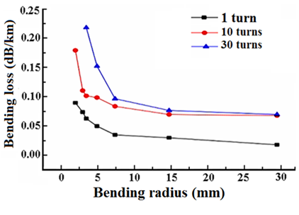
Figure 7 Bending losses in terms of bending radius for different turns at 1550 nm.8
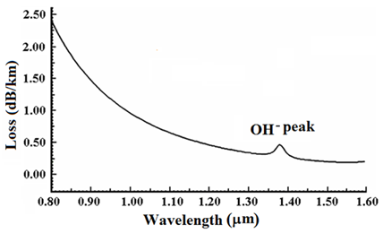
Figure 8 The calculted spectral loss variations of the MOF.7

Comparison of NOF, HOF, and MOF

We have compared the characteristic parameters of three selected fibers with different structures that are used in FTTH networks. A summary of the comparison is presented in Table 4.5-7,18 The parameters values indicate that in terms of bending loss, fiber No. 2 is better selection, while with respect to splice loss with the standard SMF, one may prefer fiber No. 1.

No.

Fiber types

Bending loss

Splice loss

(dB/turn)

 (with standard SMF)


(dB)

1

NOF

≤0.1

0.0336

2

HOF

0.011

0.0805

3

MOF/12 air–holes

0.049

0.1207


Bending radius= 5mm, Wavelength = 1550nm

Table 4 The comparison of characteristic parameters of three selected fibers with different structures

We further note that more experimental investigations could be done by considering the influence of characteristic structural parameters such as air-hole diameter d MathType@MTEF@5@5@+= feaagKart1ev2aqatCvAUfeBSjuyZL2yd9gzLbvyNv2CaerbuLwBLn hiov2DGi1BTfMBaeXatLxBI9gBaerbd9wDYLwzYbItLDharqqtubsr 4rNCHbGeaGqiFu0Je9sqqrpepC0xbbL8F4rqqrFfpeea0xe9Lq=Jc9 vqaqpepm0xbba9pwe9Q8fs0=yqaqpepae9pg0FirpepeKkFr0xfr=x fr=xb9adbaqaaeGacaGaaiaabaqaamaabaabaaGcbaqcLbsacaWGKb aaaa@375C@ , the hole pitch Λ MathType@MTEF@5@5@+= feaagKart1ev2aqatCvAUfeBSjuyZL2yd9gzLbvyNv2CaerbuLwBLn hiov2DGi1BTfMBaeXatLxBI9gBaerbd9wDYLwzYbItLDharqqtubsr 4rNCHbGeaGqiFu0Je9sqqrpepC0xbbL8F4rqqrFfpeea0xe9Lq=Jc9 vqaqpepm0xbba9pwe9Q8fs0=yqaqpepae9pg0FirpepeKkFr0xfr=x fr=xb9adbaqaaeGacaGaaiaabaqaamaabaabaaGcbaqcLbsacqqHBo ataaa@37E8@ , and the ratio d/Λ MathType@MTEF@5@5@+= feaagKart1ev2aqatCvAUfeBSjuyZL2yd9gzLbvyNv2CaerbuLwBLn hiov2DGi1BTfMBaeXatLxBI9gBaerbd9wDYLwzYbItLDharqqtubsr 4rNCHbGeaGqiFu0Je9sqqrpepC0xbbL8F4rqqrFfpeea0xe9Lq=Jc9 vqaqpepm0xbba9pwe9Q8fs0=yqaqpepae9pg0FirpepeKkFr0xfr=x fr=xb9adbaqaaeGacaGaaiaabaqaamaabaabaaGcbaqcLbsacaWGKb Gaai4laiabfU5ambaa@3984@ using large-mode area and small mode-area photonic crystal fibers.19

Conclusion

The present work has reviewed single-mode optical fiber with different structures that may be used in FTTH optical networks in conjunction with insensitivity to bending losses. In this paper, we have compared three selected fibers by considering the effects of their structures on bending losses, prominently, with respect to bending radius and operating wavelength.

By considering the results of the analyses, all three types of optical fibers at bending radii of 5mm and operating wavelength of 1550nm have different bending losses. The HOF, as compared to two other fibers, has lower bending loss of 0.011dB/turn at the given operating wavelength of 1550nm. Therefore, among these optical fibers, it can be the most suitable option for use in FTTH networks in terms of bending loss.

In continuation of the present investigation in conjunction with the reduction of the bending loss of single-mode fibers used in FTTH networks, we suggest that the influences of characteristic parameters, such as air-hole diameter , the hole pitch , and the ratio to be further studied for photonic crystal fibers of large-mode and small-mode areas.

Acknowledgements

None.

Conflict of interest

Author declares there is no conflict of interest.

References

  1. Wagner RE, Igel JR, Whitman R, et al. Fiber–based broadband–access deployment in the United States. Journal of Lightwave Technology. 2006;24(12):4526–4540.
  2. Chen DZ, Belben WR, Gallup JB, et al. Requirements for bend insensitive fibers for Verizon’s FiOS and FTTH applications. USA: OFCNFOEC; 2008.
  3. Shinohara H. Broadband Access in Japan: Rapidly Growing FTTH Market. IEEE Communications Magazine. 2005;43(9):72–78.
  4. Bing Y, Ohsono K, Kurosawa Y. Low–loss Holey Fiber. Germany: Hitachi Cable Review; 2005.
  5. Tsuchida Y, Saitoh K, Koshiba M. Design and characterization of single–mode holey fibers with low bending losses. Optics Express. 2005;13(12):4770–4779.
  6. Li MJ, Tandon P, Bookbinder DC, et al. Ultra–low Bending Loss Single–Mode Fiber for FTTH. IEEE Journal of Lightwave Technology. 2008;27(3):376–382.
  7. Luo WY, Li S, Chen W, et al. Low–loss Bending–insensitive Micro–structured optical fiber for FTTH. IWCS: The International Cable Connectivity Symposium. 2014:454–457.
  8. Matsuo S, Ikeda M, Himeno K. Bend–insensitive and low–splice–loss optical fiber for indoor wiring in FTTH. USA: Optical Fiber Communication Conference; 2004.
  9. Islam R, Rana S, Ahmad R, et al. Bend–Insensitive and Low–Loss Porous Core Spiral Terahertz Fiber. IEEE Photonics Technology Letters. 2015;27(21):2242–2245.
  10. Kozlov V. Corning bend insensitive optical fibers for elevated temperature applications. IEEE Avionics, Fiber–Optics and Photonics Digest CD; 2012.
  11. Chauhan JD, Khant SB, Parmar MR. For Fiber–to–the–home (FTTH) Architecture using Passive Optical Network (PON): A Review. International Journal of Modern Trends in Engineering and Research. 2016;3(4):673–677.
  12. Krähenbühl R, Schiess H, Cecchin C. Compatibility of Low Bend Singlemode Fibers. Switzerland: HUBER+SUHNER; 2010. p. 1–12.
  13. Marcuse D. Loss analysis of single–mode fiber splices. The Bell System Technical Journal. 1977;56(5):703–718.
  14. Hasegawa T, Saitoh T, Nishioka D. Bending–insensitive single–mode holey fiber with SMF–compatibility for optical wiring applications. Italy: Proceedings of European Conference Communication (ECOC2003); 2003.
  15. Wu F, Peckham D, Smith R. A new G.652D, zero water peak fiber optimized for low bend sensitivity in access networks. USA: IWCS 2006, Providence; 2006.
  16. Matsuo S, Nunome T, Yoshita T, et al. Design optimization of trench index profile for the same dispersion characteristics with SMF. USA: OFCNFOEC; 2007.
  17. de Montmorillon LA, Matthijsse P, Gooijer F. Bend–optimized G.652D compatible trench–assisted single–mode fibers. Proceedings 55thIWCS/Focus; 2006. p. 342–347.
  18. Crone GAE, Arnold JM. Anomalous group delay in optical fibres. Optical and Quantum Electronics. 1980;12(6):511–517.
  19. Seraji FE, Kasiri S. Optimization of Macrobending Loss in Small and Large Mode Area, Photonic Crystal Fibers. Open Access Library Journal. 2015:1–6.
Creative Commons Attribution License

©2018 Seraji, et al. This is an open access article distributed under the terms of the, which permits unrestricted use, distribution, and build upon your work non-commercially.