MOJ
eISSN: 2574-9773


Mini Review Volume 2 Issue 2
1Department of Mechanical Engineering, University of Texas, USA
2Department of Chemistry, University of Texas, USA
3School of Earth Environmental and Marine Sciences, University of Texas, USA
Correspondence: Mataz Alcoutlabi, Department of Mechanical Engineering, University of Texas, Rio Grande Valley, Edinburg, TX 78539, USA
Received: December 28, 2017 | Published: April 20, 2018
Citation: Campos H, Ayala J, Valdes C, et al. The use of Fe3O4/Carbon composite fibers as anode materials in lithium ion batteries. MOJ Poly Sci. 2018;2(2):44-46. DOI: 10.15406/mojps.2018.02.00045
In the present work, results on the synthesis and mass production of polymer/ceramic composite fibers through Forcespinning® (FS) are reported. Magnetite (Fe3O4), has been considered as a good anode material for Lithium‒Ion Batteries (LIBs) due to its high theoretical capacity (~924 mAhg-1), low cost, and low toxicity. The Fe3O4/carbon composite, in the present study, was achieved through Forcespinning iron (III) acetylacetonate /polyacrylonitrile (PAN) precursor solution with stabilization in air at 280°C followed by carbonization at 600°C under argon. The electrochemical cyclic performance of Fe3O4/C composite fibers was investigated by galvanostatic charge/discharge experiments. The results showed the Fe3O4/C composite fiber anode exhibited higher reversible capacity of 300 mAhg-1 after 100 cycles at a current density of 100 mAg-1 compared to that of carbon fibers, which was approximately100 mAhg-1. In addition, the Fe3O4/composite fiber anode showed improved capacity retention and better rate performance than pure carbon fibers.
Keywords: Fe3O4/composite, polymer, fibers, Forcespinning®, anode, Lithium ion battery
PAN, polyacrylonitrile; PVP, polyvinylpyrrolidone; PVA, polyvinyl alcohol; DMF, N, N‒dimethylformamide; Fe3O4, magnetite; Fe2O3, ferric oxide
Most of the current commercial LIBs use graphite as an anode material due to its long cycle life, low working potential, and low cost. But the low theoretical capacity of graphite (372 mAhg-1) limits the effectiveness of graphite as a anode material compared to other active materials such as silicon, lithium metal, tin oxide, among other metal oxides.1,2 Most carbonaceous materials used in LIBs are processed from polymer precursors such as PAN, Polyvinylpyrrolidone (PVP) and polyvinyl alcohol (PVA). To circumvent the low capacity of the graphite anode, new anode materials have been explored such as the use of polymer‒based nanostructured materials including graphene, carbon nanofibers, and composite nanofibers.3,4 Among these nanostructures, composite nanofibers have shown much promising as electrode materials for LIBs. The nanofiber structure provides high Li+ diffusion as well as increased number of lithium storage sites.3 Polymer and polymer composite fibers are frequently produced through electrospinning, melt blowing, liquid shearing spinning, magneto spinning and Forcespinning® (FS).3,6,7 In our previous work, TiO2/C, Sn/C and SnO2/NiO/C composite fibers were prepared through the FS of polymer/ceramic precursors and subsequent thermal treatments, and were directly used as anodes for LIBs.7‒9 Electrospinning has been used to prepare Fe2O3 and Fe3O4 composite nano/micro fibers for LIBs electrode materials.10‒12 The main goal of the present work is to use Forcespinning to produce binder free Fe3O4/C composite fiber anodes for LIBs. The electrochemical performance and rate performance of Fe3O4/C composite fiber anodes were investigated using a current density of 100 mAg-1 and voltages ranging from 0.05 to 3.0 V. To the best of our knowledge, this is the first time results on the Forcespinning of Fe3O4/C composite fibers for use as anodes in LIBs has been reported.
In this work, Poly (acrylonitrile) (PAN) with an average molecular weight of 150,000 gmol-1, N, N‒dimethylformamide (DMF) (≥99.8%), and iron (III) acetylacetonate (FeACAC) (≥99.8%) were purchased from Sigma‒Aldrich USA. The precursor solution consisted of 88 wt% DMF to 12 wt% of solute. The solute was a mixture of 85 wt% PAN and 15 wt% FeACAC. The precursor solution was prepared by adding FeACAC into DMF and mechanically stirring the mixture for up to 12 h. The control carbon fibers were prepared using a precursor solution consisting of 12 wt% PAN in 88 wt% DMF. The microfibers prepared from the iron precursor and control precursor solutions were spun at a rotational speed of 7000 rpm. Subsequent to spinning the collected fibrous mats were dried at 120°C in a vacuum oven for 12 h to remove residual solvent. After drying, both the control PAN and PAN/FeACAC fibers were stabilized in air at 280°C for 4 h, followed by carbonization under argon at 600°C for 6 h (using a heating rate of 3°C/min). The morphological and elemental information of the Fe3O4/C composite fibers and carbon fibers were evaluated using the scanning electron microscopy (SEM) and energy dispersive X‒ray spectroscopy (EDS), powder X‒ray diffraction (XRD). The SEM and EDS date were collected a Sigma VP Carl Zeiss equipped with a TEAM EDS Enhanced Analysis System., and x‒ray diffraction (XRD). For the XRD data collection the Fe3O4/C composite fibers were ground into a fine powder and homogenized using a mortar and pestle. The powder XRD patterns for the samples were collected using a Rigaku Miniflex powder X‒ray diffractometer.
The electrochemical performance of the Fe3O4/C composite electrodes was measured using 2032 coin‒type cells. The electrolyte was a 1M solution of LiPF6 salt in ethylene carbonate (EC)/dimethyl carbonate (DMC) with a 1:1 v/v ratio. The cells were assembled in a glove box (MBraun, USA) under argon. The electrochemical performance was evaluated using galvanostatic charge‒discharge experiments at a current density of 100 mAg-1 with the voltage ranging between 0.05 V and 3 V.
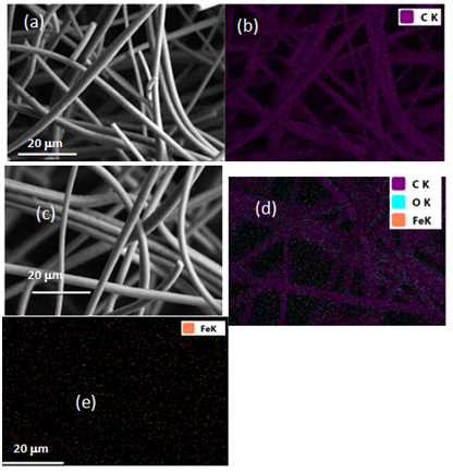
Figure 1 shows the SEM images collected from the control and Fe3O4/C composite microfibers. The average diameter observed for the control microfibers (Figure 1A) was determined to be 3.02±0.37 μm. Elemental mapping analysis (EDS) showed that the fibers consisted of carbon (Figure 1B). The Fe3O4/C composite microfibers (Figure 1C‒1E) showed a slightly larger average diameter of 3.26±0.16 μm. The presence of iron in the Fe3O4/C microfiber matrix can be seen in the EDS map of the sample (Figure 1D). The dispersion of the iron within the carbon fiber was confirmed by EDS mapping of Fe as can be seen in Figure 1E. There were no observable continuous bright spots in the iron map, indicating the iron was dispersed throughout the sample.

Figure 1 (A,B) SEM and Elemental mapping of the carbon microfibers. (C, D and E) Fe3O4/C composite microfibers.
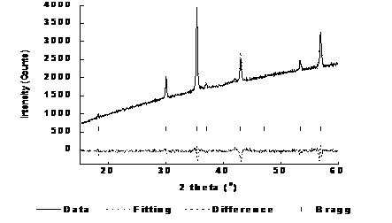
Figure 2 shows the collected XRD data, the Full prof Lebail fitting of the sample, the difference between the fitting and the sample data, as well as the Bragg peaks for the synthesized Fe3O4/C microfibers. As can be seen in Figure 2, there is very little difference between the fitting and the actual XRD data as indicated by the small residual in the difference pattern.13,14 The small residual between the fitting and the data indicates that the iron present in the sample is Fe3O4. The amorphous nature of the carbon present in the sample did not allow for the fitting of the carbon phase. The Bragg peaks shown in the diffraction pattern at 18.28, 30.08, 35.43, 37.06, 43.05, 47.14, 53.41, 56.93, and 56.93° in 2θ correspond to the 111, 220, 311, 222, 400, 331, 422, 333, and 511 diffraction planes consistent with the Fd3M crystal structure of magnetite.15
Figure 3A & Figure 3B show the charge/discharge profile of the control fibers and the Fe3O4/C composite fibers at 100 mAg-1, respectively. The initial discharge capacity for the Fe3O4/C composite fibers was 915 mAhg-1 which is much higher than the discharge capacity of the control fibers (507 mAhg-1). The charge capacities (Li‒deinsertion) at the 1st cycle for the control and Fe3O4/C composite fibers were 98 mAg-1 and 333 mAg-1 which resulted in initial Columbic efficiencies of 20% and 37%, respectively. The wide variance in the initial charge and discharge capacities for the Fe3O4/C composite fibers has been observed in Li‒ion batteries and is primarily attributed to the formation of the SEI layer during the first cycle and the high surface area to volume ratio observed in microfibers. The capacity recovery for the control fibers was minimal and was observed between the initial charge and 100th discharge cycles. At the end of the 100th cycle, the charge capacities were observed to be 127 mAhg-1 for the control fibers and 328 mAhg-1 for the Fe3O4/C composite fibers. In addition, the control fibers were observed to suffer from a high loss in capacity at the first cycle, which can be attributed to the high surface area of the fibers and the formation of the SEI layer.

Figure 3 (A) Charge/Discharge profiles for carbon fibers. (B) Fe3O4/C composite fibers carried out at a current density of 100 mAg-1.
The rate performance of the carbon and Fe3O4/C composite fibers was evaluated by carrying out charge/discharge experiments for 10 cycles at current densities of 50, 100, 200, 400, and 500 mAg-1 and recycled back at 50 mAg-1. The results of the rate performance are presented in Figure 4A & Figure 4B for the control fibers and the Fe3O4/C composite fibers, respectively. Both the carbon and Fe3O4/C composite fiber electrodes showed capacity recovery when the anodes were cycled at an initial current density of 50 mAg-1. The carbon fibers and Fe3O4/C composite fibers‒delivered a charge capacity of 160 mAhg-1and 268 mAhg-1 after 10 cycles at 50 mAg-1, respectively. The discharge capacities of the carbon and Fe3O4/C composite fibers show degradation at high current density of 400 and 500 mAg-1. Furthermore, a degradation in the reversible capacity was observed when the anodes were cycled back at 50 mAg-1, resulting in reversible capacities of 124 and 306 mAg-1, for the carbon and Fe3O4/C electrodes, respectively. The Fe3O4/C composite electrode shows improved rate performance, compared to the control C‒fibers at low current densities and high capacity recovery after 60 cycles.
Fe3O4/C composite fibers and carbon fibers were prepared by Forcespinning and subsequent thermal treatments and were directly used as binder‒free anodes for LIBs. The electrochemical performance of the Fe3O4/C composite fibers showed improved cycling stability, enhanced specific capacity, good capacity retention as well as capacity recovery over 100 cycles. To the authors’ knowledge this is the first report results on the synthesis of Fe3O4/C composite fibers using FS in combination with a solvo thermal method for applications in LIBs. The use of the FS shows high potential to yield a high amount of fibers in a short period of time, potentially increasing production rates. The processing method discussed in this work could be widely applied for the large production rate of binder‒free composite fiber electrodes for a wide range of applications including Lithium‒ion and sodium ion batteries, and supercapacitors.
None.
The author declares there is no conflict of interest.

©2018 Campos, et al. This is an open access article distributed under the terms of the, which permits unrestricted use, distribution, and build upon your work non-commercially.