Proximal Femur Nail in Intertrochanteric Fractures Indications and Tips/Tricks
Vijay Panchanadikar
Regret for the inconvenience: we are taking measures to prevent fraudulent form submissions by extractors and page crawlers. Please type the correct Captcha word to see email ID.

Department of Orthopedics, Deenanath Mangeshkar Hospital Krishna General Hospital, India
Correspondence: Vijay Panchanadikar, Consultant orthopedic surgeon and DNB guide, Deenanath Mangeshkar Hospital, Krishna General Hospital, Pune, India
Received: May 12, 2016 | Published: July 27, 2016
Citation: Panchanadikar V (2016) Proximal Femur Nail in Intertrochanteric Fractures Indications and Tips/Tricks. MOJ Orthop Rheumatol 5(3): 00178. DOI: 10.15406/mojor.2016.05.00178
Download PDF
- Maintaining the proper neck shaft angle.
- Placing the Lag screw (Compression Screw) in the centre of hip (or sight inferior).
- Compression screw first. (inferior lag screw).
- Hip pin should be shorter by at least 15mm.
Successful result depends on good fracture reduction and implant position
The risk of cut-out is directly dependent on the quality of fracture reduction and on implant position.1
Tip apex distance not important in PFN
Tip apex distance is probably not as important in Proximal Femur nail as it is in Dynamic Hip screw as TAD scale is linear and not multidirectional 2
Difficulties in PFN
- Only 2 angles are available in PFN 130 and 135 degrees.
- In PFN we are first passing IM nail then head screw.
- Technology dependant. Good quality instruments a must as cannulated instruments and implants have to pass through nail over guide wire.
- Learning curve.
- Study Head size/Neck size to see whether it will accommodate 2 screws.
- Study Neck Shaft angle on opposite hip. Too much varus may make it unsuitable (Figure 4).
- In case of failure to get closed reduction or in case of failure to obtain good valgus angle of head and neck proceed to open reduction or switch to DHS. Only 2 angles are available in PFN 130 and 135 degrees.
- Back up option of DHS/ DCS/Extra long plate/TSP to be ready.
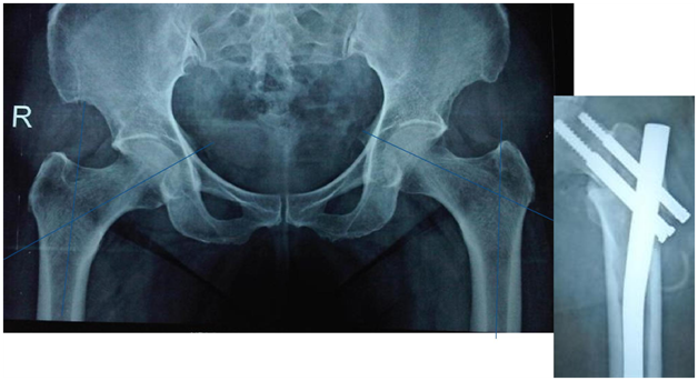
Figure 4 Beware of Varus. So common in Indians.
Key steps and instruments to ensure good fracture reduction and implant position, and facilitate surgery
- Good infrastructure/instruments must.
- Good C positioning and closed reduction.
- If CR fails open/limited open reduction.
- Accurate Entry point.
- Correct proximal reaming path.
- Distal Incision for spikes, reduction clamps or circlage for assisting reduction.
- Use of curved internal reduction device to pass the guide wire in correct direction.
- Tight Nail assembly and easy Nail passage.
- If nail not progressing, ream ream ream. Do not hammer.
- Good positioning of head screws in AP and lateral view.
- Efficient distal locking.
Routine and special Instruments
- Proximal reamer
- Internal reduction device to redirect Guide wire,
- Sleeve with Multiple parallel holes
- Large sleeve (Figure 5)
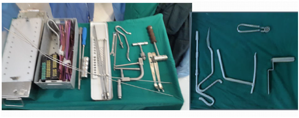
Figure 5 Routine and special Instruments.
Position on traction table
- C position on fracture table with eccentric perineal post (Figure 6).
- Closed reduction is a must. If not proceed to open reduction.
- Maintain 5-10 degrees adduction.
- Heavy traction ensures closed reduction. But heavy traction may result in disappearance of dorsalis pedis pulse.
- Heavy traction may lead to loss of adduction.
- Keep limb in 5-10 degrees of external rotation. Double check position of patella under drapes in order to prevent fixation in internally rotated position.
- Tilt table to Elevate the fracture side by 5-10 degrees as this helps in exposure (Figure 6).
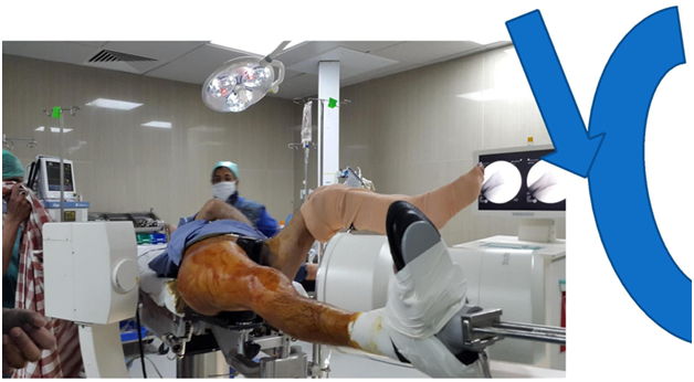
Figure 6 Good table for C positioning check for good lateral view beforehand.
Failure of closed reduction
- If there is failure of closed reduction better to open the fracture and achieve reduction by bone spikes/reduction clamp/ circlage wire etc.
- Nail will not ensure reduction.
- If reduction is not there the head screws will go into malposition (Figure 7).

Figure 7 Failure of closed reduction.
Exposure of entry point
- Adequate incision just proximal to greater trochanter (Figure 8).
- Deepen through tensor fascia lata
- Cut Gluteus medius insertion in line with middle of trochanter and palpate the tip of trochanter.
- Entry point while seeing in AP view.
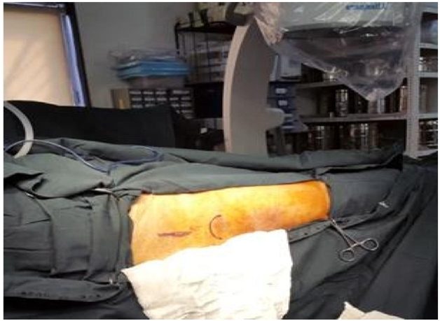
Figure 8 Incision. Proximal and in line with Greater trochanter.
Entry point
- Dead AP is 10 degree tilt of C arm.
- Entry by guide wire and special sleeve with multiple options at the trochanteric tip (Figure 9).
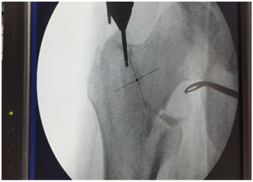
Figure 9 Entry by guide wire and special sleeve with multiple options at the trochanteric tip.
For change of entry point
- Use Special sleeve with multiple options (Figure 10).
- Eccentric reaming by awl while keeping the first Guide wire is possible.
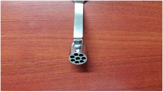
Figure 10 For change of entry point.
Distal Incision for spikes or circlage
- Distal incision onto the lateral aspect of upper thigh corresponding to the future entry point of guidewires onto head and neck. Deepened to the bone and use this window for reduction of fracture or medial pushing of fracture/fragments to facilitate guidewire entry.
- Spike from proximal incision anterior aspect can go onto neck to correct version and to push down on anterior displacement of fracture spike.
Entry point to be at tip with medial bias
In AP view entry point to be more medial. This allows 2 screws in head in good position (Figures 11&12).3
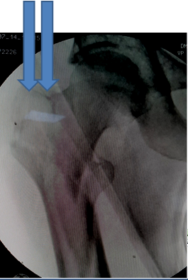
Figure 11 Entry point to be at tip with medial bias.
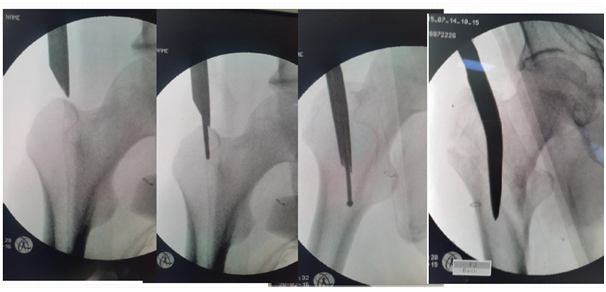
Figure 12 Entry point by femur finder, Cannulated awl. Curved awl can ensure entry medial to GT and reaming parallel to lateral cortex.
If too lateral entry point
If starting point is placed lateral to the tip of the trochanter it may result in varus malreduction (Figure 13).4-7

Figure 13 Lateral entry point, pushed proximal fragment into varus and screws into malposition.
Use of curved femur finder device, retractor push, cannulated curved awl to pass the guide wire in correct direction (Figures 14-17).

Figure 14 Guide wire in canal deviating medially.
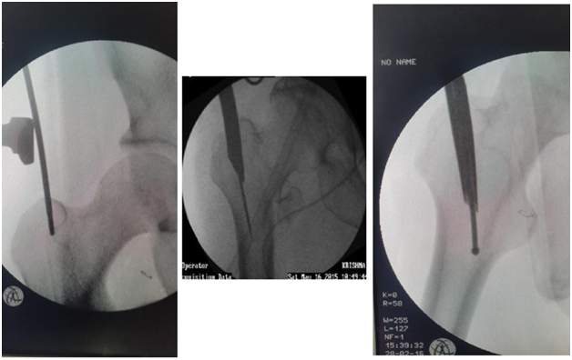
Figure 15 Redirection by Retractor push, Femur finder, Cannulated awl.4
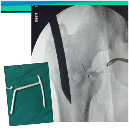
Figure 16 Guide wire going medially sometimes can exits out through fracture and damage neurovascular structures.
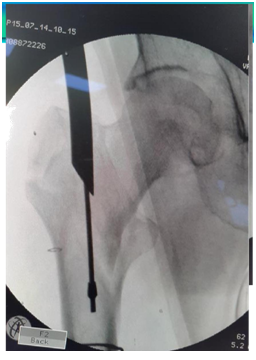
Figure 17 Redirected Guide wire in canal.
Proximal reaming must to accommodate broad proximal part of nail
- Reamer to be pushed medially at entry point to break cortex so that reamer and nail is not displacing the fracture, as it leads to malposition of screws in head (Figure 18).
- Reaming on guide wire up to the length and breadth of proximal part of nail up to lesser trochanter. Otherwise nail may not progress distally (Figure 19).
- Reaming parallel to outer cortex/intact anterior or posterior cortex.
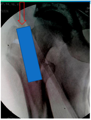
Figure 18 Cut a correct path. Reamer to hit lateral edge of proximal fragment for correct path.5
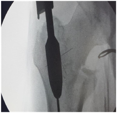
Figure 19 Proximal reaming must to accommodate broad proximal part of nail.
Remove Guide wire early, (Figure 20).
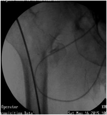
Figure 20 Guide wire may sink in canal while pushing nail down. Remove Guide wire early on.
Guide wire may sink in canal while pushing nail down. Remove Guide wire early on.
Nail assembly and passage
- Check nails side and size, assembly side and curve, yourself.
- Check after assembly sleeves and if Drills reamers are passing through nail holes.
- Look for play.
- Tighten assembly bolt well otherwise if loose sleeves/screws/distal bolts do not pass accurately.
- Apply Betadine to sleeves so they slide easily.
- Hammer sleeve in to touch cortex. Remove intervening soft tissues like fascia lata (Figure 21).
- Sleeve has tendency to Skid upwards, (proximally), entry hole is then proximal creating difficulty for passage of reamer. Push down on cortex/sleeve at drill entry (Figure 22).
- If nail not progressing do not hammer specially in Short ladies with narrow canal. Ream REAM REAM. Do not Hammer or only last 1 cm or otherwise there is risk of intraoperative fracture extension (Figure 23).
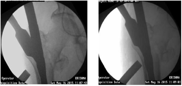
Figure 21 Hammer sleeve in to touch cortex. Remove intervening soft tissues like fascia lata.
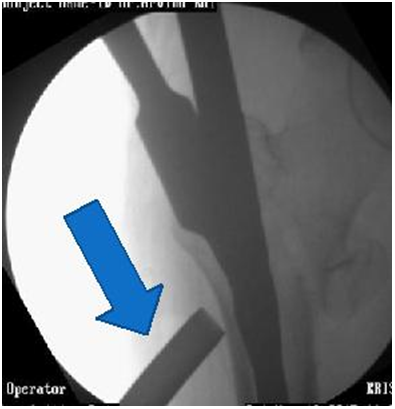
Figure 22 Sleeve has tendency to Skid upwards, (proximally), entry hole is then proximal creating difficulty for passage of reamer. Push down on cortex at drill entry.
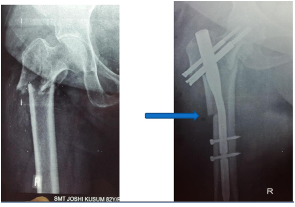
Figure 23 Risk of intraoperative fracture extension.
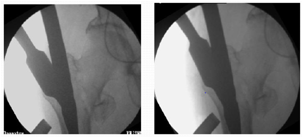
Figure 24 Increase traction to get good valgus.
Drill and Guide wire
- The guide wire can bend at outer cortex also but this can be prevented with predrilling the entry point at lateral cortex with a drill.8(Figure 25).
- Of the two guide wires first pass the one that you think is at edge of neck not centre of neck, so revision by adjusting position of nail is easy (Figure 25).
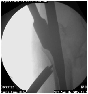
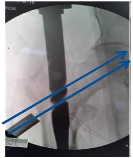
Figure 25 Predrilling the entry point. Of guide wires first pass the one that you think is at edge of neck.
For good positioning in AP view
- Medial entry point
- Heavy traction to get good valgus (Figure24).
- Abduction,
- Push in with jig, push out distal fragment/thigh
- Push on fracture
- Push down by spike superior to neck.
For good positioning in lateral view
- Lift up fracture by sheet under hip.
- Lift up fracture by hand to remove sag to allow good positioning in lat view.
- Lift up fracture by bone spike posteriorly or Jig.
- Rotate jig for change of version (Figure 26).
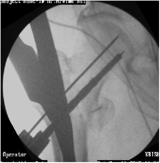

Figure 26 Good positioning in AP/ Lateral view.
Drive wires deep
- Drive deep or wire comes out at reaming (Figure 27) but not into joint. If it breaks one has a major problem…
- Reinsert wire if comes out or else screw may change direction (Figure 28).
- Check length by use of another same length wire on bone edge (Figure 29).
Rotate jig to either side to avoid shadow of jig handle (Figure 30).
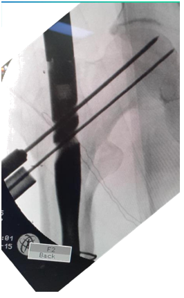
Figure 27 Drive wire deep.
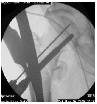
Figure 28 Reinsert wire if comes out.

Figure 29 Checking length by use of another same length wire on bone edge.
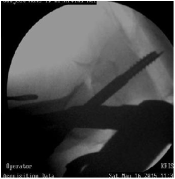
Figure 30 Rotate jig to either side to avoid shadow of jig handle.
Reaming
- Rotate reamer in forward direction only to remove so threaded wire doesn’t disengage and come out (Figure 28).
- Hand reamer over Guide wire may be better.
If guide wire is going in same track
- Thicker wire
- On full power then gentle forward tug, feel to engage, then forward.
- While changing wire or screw, keep existing, introduce the second, then revise first one so fracture remains fixed.
- Non progression of screw may be because of bending of guide wire. Even breakage
- Withdraw wire and pass screw.
Reaming difficulty
- If reamer is not progressing on guide wire a) May be hitting edge of nail gentle forward backward motion may help. b) Guide wire may be stuck in reamer.
- Start with smaller reamer
- Hand ream
- Ream reverse.
- Ream with smaller reamer
- Ream after removing Guide wire.
- Ream after removing outer sleeve.
- Change direction of reamer by seeing in Carm where it is hitting nail.
- Full length reaming may not be necessary. Try passing screw directly, carefully.
Hip pin and compression screw
Hip pin to be shorter than compression screw. Deep positioning to maintain tip apex distance. Head screws to be tightened alternately for compression. But may sink inside bone (Figure 31,32).
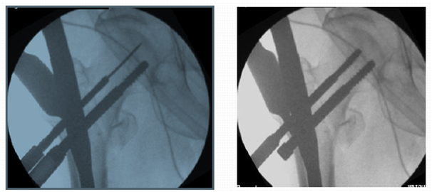
Figure 31 Hip pin to be shorter than compression screw. Deep positioning to maintain tip apex distance.
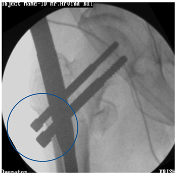
Figure 32 Head screws to be tightened alternately for compression. But may sink inside bone.
Reaming if Guide wire bends
- Hand reamer.
- Reverse reaming forward.
- Gentle to and fro.
- Gentle forward and backward.
- Mostly bend straightens out. But careful. May break hence remove early (Figure 31 & 32).
Before distal locking
- Chance to correct rotational deformity.
- Palpate patella hidden under drapes.
- Release traction. Impact if fracture transverse.
- Do not impact if comminuted.
- Drill far cortex well as otherwise bolt may not progress. Specially in midshaft with thick cortex.
- If drill hits on nail switch to smaller drill bit or thick K wire. May use smaller bolt or cortex screw.
- Check length of bolt in Carm before final tightening of bolt, as changing of bolt is tedious (Figure 33). Tying Vicryl to bolt is an option.
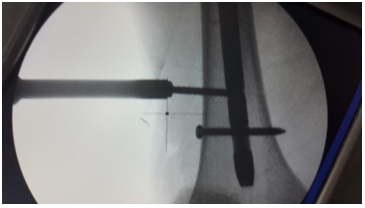
Figure 33 Before distal locking.
Jig removal
- Jig removal is difficult at times, jammed and has to be hammered out.
- Application of end cap is at times difficult (Figure 34).

Figure 34 Application of end cap is at times difficult.
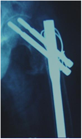
Figure 35 Special situations. Add TBW in case of split of GT.
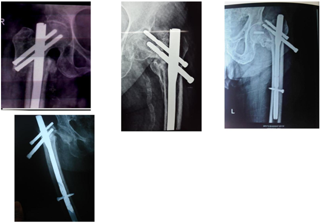
Figure 36 Complications. Some can be prevented, others may be not.


